development of android heads with very complex behaviors. [3]. ... University of Vigo, 36200 Vigo, Spain (phone: +34 986 812222; fax: +34 .... Reset button. 11.
Building a robot head: Design and control issues Gustavo Barciela, Enrique Paz, Joaquín López, Rafael Sanz and Diego Perez
Abstract—Physical appearance and behavior of a mobile robot are important issues in applications that need to interact socially with humans. The robot must have ways of expressing its internal state. With this ability, people that interact with the robot will know its “mood” in a similar way that we can guess the mood of a person looking at his face. The robot behavior must take into account all the different kind of sensors to obtain stimulus about the environment and people interacting with it. In order to obtain behavioral consistency, a general control architecture that allows the connection of all components and modules is necessary. In this paper we describe the design of a robot head and its integration in the RATO control architecture. The head has been mechanically designed to show different expressions and reproduce human-like movements. The head control system is responsible to coordinate the different servo motors that switch between different expressions and produce the movements required by the administrative level modules. The basic behaviors that associate stimulus with expressions and sequences of actions are modeled using Petri Nets. Finally we will present the results in a robot guide application. Index Terms— Mobile robots, robotic head, human robot interaction, robot guide. I.
INTRODUCTION
T
here are a lot of mobile robot applications that need to interact with people. According to several authors [1], [2], [3], in order to interact socially with humans, a software agent must have behavioral consistency, and must have ways of expressing its internal states. Much research has already been conducted in the area of non-verbal communication between a robot and a human that include facial expression [4], [5], [6], [7] that focuses on the communication task. Also, several mobile robot guide applications [8], [9] have been developed that mainly focus on the navigation and guide tasks. However, we are more interested on the integration of the daily guide tasks with the communication tasks in order to make the robot guide more attractive to the public. Worldwide, several research projects focus on the development of android heads with very complex behaviors [3]. Other projects [10] focus on obtaining the appearance of a human head. There are also some companies such as Handsonrobotics that design, develop and produce interactive bio-inspired conversational robots, including the world-famous Albert-Hubo head. Instead, we will focus on building a cheap, simple, easy to integrate in the RATO´s control architecture and very expressive head. This work was supported in part by the Spanish Comisión Interministerial de Ciencia y Tecnología, CICYT, project DPI2005-06210. The. Authors are with the Dep. Ingeniería de Sistemas y Automática, University of Vigo, 36200 Vigo, Spain (phone: +34 986 812222; fax: +34 986814014); e-mail: (gbarciela, epaz, joaquin, rsanz, dplosada)@uvigo.es.
After several years of mobile robots research, our first experience in a robot aplication interacting with people was a tour guide robot for the “Xuventude Galicia Net” event that took place in Santiago de Compostela (Spain) during three days in March 2007. The platform used was a modified Peoplebot from ActivMedia with a laser range, a voice system and a laptop that was used to do all the processing and user-interface tasks. One of the conclusions of that project was that the physical appearance and behavior of the robot are important assets in terms of Human-Computer Interaction. Even the organizers and some attendants at the event let us know that we should provide the robot with a head. Expressions that show emotions play an important role in inter-human communication because, for example, the recognition of the mood of a conversational partner helps to understand his/her behavior and intention. For the 2008 edition we planned to update an old B21 named RATO replacing the connections of most of the original sensory system for a CAN bus. We had previous experience in building a robotic head and we have one since 2005 [11]. However, for this year’s edition we planned to build a new one that integrates better with the RATO current sensory and control systems. The design and control including the integration in the robot control architecture is described in this paper. The face can show expressions analogous to happiness, sadness, surprise, boredom, anger, calm, displeasure, fear, etc. The rest of this paper is organized as follows. The next section introduces the head design. It is divided in three subsections that describe the mechanic, motor and electric system. Section III describes the bus that connects the different robot devices and section IV introduces the RATO control architecture. The integration of the head control modules in this architecture is shown in section V including some behavior examples. Finally, section VI shows the results in a robot guide application and concludes the paper. II.
HEAD DESIGN
The head should be designed taking into account that the different head expressions must be easily recognized by a human being [12]. The Uncanny Valley theory [13] states that as a robot is made more humanlike in its appearance and motion, the emotional response from a human being to the robot will become increasingly positive and empathic, to a point where the response quickly becomes that of strong repulsion. However, as the appearance and motion continue to become less distinguishable from a human being, the emotional response becomes positive once more and approaches human-to-human empathy levels. Some roboticists [14] have criticized the theory, and other
researchers [15] consider the uncanny Valley crossed at some level. Even though these android heads might look like a human head, so far their motion is quite different. Animated heads can be so expressive or even more than android heads and they are usually easier to control. Since our main interest is the expressivity, we decided to build a simple animated head. We can see in fig 1 that a face with eyes, eyebrows and moth is universally recognized and can show a quite wide range of expressions.
Figure 1. Face expressions
These elements are actually enough for most of the animated cartoons to be very expressive. Since our goal is expressiveness rather than make an android face, they will be the basic elements of our robotic head. A. Mechanical design The head has two main parts: the neck and the head. The neck is a Pan-Tilt unit PTU-46-17.5. It has two degrees of freedom. The pan movement is used to turn the face towards the visitors and nodding while the tilt movement allows shaking the head. This model can move 1.6kg. weight at a speed of 300 deg/sec. The movement resolution is 0.0514 degrees. The unit is connected to the computer on-board using a RS-232 cable allowing control of the position, speed and acceleration.
part of the structure. Some components of the structure are even located bellow the connection point between the head and the neck. However, there are some relatively heavy elements such as the cameras that need to be placed in some defined points. We locate most of the servo motors in the base of the structure because they constitute a high percentage of the head’s weight. Movement to the different elements (eyes, eyebrows, eyelids, mouth, etc.) are actuated via bar linkages. B. Motor System The neck has two DoFs that provide horizontal and vertical movements that can be combined. The face has ten degrees of freedom providing the following movements: • Eyes up and down. • Eyes to the sides. • Left eyebrow. • Right eyebrow. • Open and close the mouth. • Lips. • Right eyelid (open and close). • Left eyelid (open and close).
Figure 3. Robot head mounted on Rato.
Figure 2. Head mechanical structure
The head’s mechanical structure (fig. 2) is made of aluminum folded sheets 2.5 mm thick. The parts are joined by aluminum rivets 3 mm in diameter. We have chosen aluminum to build the structure because it is light and easily malleable. Only a few axes are made of stainless steel to endow them more mechanical resistance. The Pan-Tilt unit that we are using has a rather low payload. Therefore, the head must be light and the gravity center must be as closer as possible to the Pan-Tilt unit. For this reason we need to place most of the weight in the lower
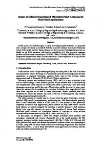
All DoFs are actuated by standard hobby grade servo motors as used in radio controlled cars or air planes. Eight of them are model DY-S0210 from Dong Yang and two HS-300 from Hitec for the eye movement. After different tests with both models, we found that the DY-S0210 servos are quite loud so we plan to replace them all for HS-300. We have chosen these kinds of motors because it is quite simple to work with them and they do not need to move heavy parts of the head. The eyes are two webcams that we use to transmit images to a web page since so far we are not doing image processing on the robot. C. Electric design We have designed a new card (fig 4) to control the servos and communicate to the CAN master. The card has been designed to control 16 servos but so far we use only 10.
1. PIC 18F458 2. Servo Motor connectors 3. Power connection 4. Servo power connector 6. Can connector
7. Transceiver 8. Programmer connector 9. Oscillator 10. Reset button 11. Status LEDs
Figure. 4. Slave card to connect 16 servo motors. The PIC program generates the PWM signals to control the servos and processes the CAN messages. There are four LEDs that provide information about the state of the system: • Red: shows when the servos are powered. • Yellow: shows when the card is powered. • Green: There are two green LEDs connected to the B0 and B1 PIC inputs. They show whether the CAN servos and virtual encoders are activated. The card has different connectors for power, programming, servo connectors, servo power connector and CAN bus connector.
simple CAN server handles the connection and disconnection of the different slaves loading the corresponding driver. This is done in a similar way that USB devices can be plugged and unplugged to a computer and the driver will be loaded accordingly. For example, if a module with sonar sensors is connected, the CAN server will first register and initialize the new module connection and then it will identify the module to hand over the messages to the sonar-driver. Modules can be connected at any time and in any order. Connection and disconnection is detected using a watchdog message (any frame or a special watchdog frame if no other frame is issued for the watchdog period). When a slave is connected to the bus, it starts sending a watchdog periodically. The master realizes that there are new connected modules (begin receiving watchdog) or disconnected (no getting frames from the module during watchdog period). In the case of connecting a new module, the master will send information to configure the slave and change the watchdog time. If the master does not receive the watchdog of a slave for a period longer than a timeout, it assumes the slave is disconnected or has some error and it will be notified to the control programs interested in the slave data. The slave modules have an Identifier (ID) that can be any even number and the master module can send frames to a specific slave using ID+1 or as a broadcast frame. On the other side, each slave module will filter all the frames except the broadcast frames and frames directed to it (ID+1).
III. COMMUNICATIONS IN THE ROBOT The robot RATO is an old modified B21 RWI platform with a ring of 24 sonar sensors and 24 bumpers on the enclosure controlled with four CAN slave modules attached to the computer through a CAN-USB adapter card [20]. The base is controlled with another two CAN slave modules.
Figure 6. Head CAN-Slave module status sequence.
Figure. 5. CAN based master slaves communications. Master includes different drivers.
Fig. 5 shows how the different slaves (sensor-actuator modules) are connected to the master (control module). Control modules are running on a PC attached to CAN bus using a CAN-USB adapter. CAN master process is implemented as shown in fig. 5. A
A. RoboCan master module The RoboCAN master module handles the connection of the different slave modules and configures them if necessary. It starts without any slave module registered. When a message from a new slave module is detected, it will create a new instance for this new module that will evolve according to the states depicted in fig. 6. After detecting the first message for this new module, the status will be “Detected” and a new message to this new module will be sent asking for information about the module in order to initiate the drivers to handle the sensor-actuators of
this new slave. A driver deals with the information of all the sensor or actuators of the same kind. If the information for this module is ok and all the drivers are correctly initiated, the new module is registered as “Connected” and information obtained from it will be passed to the drivers. The new module can be disconnected as a request for the master or due to a timeout (fig. 6). If a module is disconnected, all the associated drivers will be notified. B. RoboCAN head slave module Fig. 7 shows the state graph of the head slave module. For the control of this module we divide the functionality of each servo motor in a virtual sensor and an actuator. CAN frames will be issued (green ellipses) in three different cases. The first is published as a reply from some information request (module, sensor or motor information). The other two are frames published periodically for the sensor polling and module watchdog mechanisms. The sensor polling is maintained as an encoder mechanism to keep track of the servo positions. The watchdog mechanism guarantees that a frame is sent every “watchdog period” time while it is connected, if the module does not need to transmit a frame during that time, a watchdog frame will be issued. Send sensor
watchdog frame
Sensor timeOut
Servo motor action
Module timeout
Command servo
Waiting
Reset module frame
Module config frame
Frame info request Servo config frame
Reset module
Configure servo
Send info frame
CAPTIONS:
Sensor config frame
Configure module
Configure sensor
CAN action other actions Set params
CAN event other event
Set params
Figure 7. Slave module main program (on PIC 18F458). On the other side, different actions should be taken (yellow ellipses) when “module configuration”, “sensor configuration”, “servo configuration”, “reset module” or “servo command” frames are received. Module configuration frames are issued to configure different module parameters such as the watchdog time. Actuator configuration frames include “disable motors”, “enable motors” and “servo motor configuration”. Sensor configuration frames are issued to configure parameters related with the virtual sensors. They include “disable sensors”, “enable sensors” and “sensor config.”. There are information frames (query and request) regarding the module, virtual sensors or servo motors. The slave module is unaware of eventual disconnections
from the master. If the time the slave remains disconnected is shorter than “watchdog period” the master may not detect the disconnection. On the other case, for longer disconnections, the master will restart the slave module. IV. CONTROL ARCHITECTURE The control architecture named ISANAV is a modular control architecture that is organized as shown in figure 8. Even though the different modules are organized in four sets, they can be mapped in the three layer architecture popularized by Bonasso et al. [16]. The hardware servers and control set implement the functional layer while Task Dispatch implements the executive and planning layer. Finally ISANAV includes a set of processes to interact with the users and connect to other process for Multirobot applications. The navigation platform is based on CARMEN [17] and some modules such as localize, navigator and base hardware servers remain basically the same. Unlike CARMEN, motion control is divided into high-level (strategic) planning [18] and lower-level (tactical) collision avoidance using the Beam method [19]. A. Hardware server modules The hardware server modules govern hardware interaction providing an abstract set of actuator and sensor interfaces and isolating the control methods from the hardware details. Most of the hardware devices are connected to a CAN bus using RoboCAN [20]. Some of these devices are used in navigation such as the laser and sonar while others are specific for the application such as the robot head, sound and speech system, etc. The hardware servers also provide low-level control loops for rotation and translation velocities. Thanks to this layer changes in hardware components can be made without changes on higher layers modules while keeping the same interface. B. Control modules The control modules integrate sensor and motion information to provide improved sensor odometry, provide basic navigation capabilities (localization, path planning, follow path, etc) and basic application specific functions (say text, make expression, etc). C. Executive modules All the modules in this layer belong to the RoboGraph application that includes two modules (figure 8): task editor that is used only for application development and task dispatch without graphical interface that should be working when the robot is doing surveillance operations. This layer uses hierarchical interpreted binary Petri nets [22] to coordinate the activity of all the rest of the modules. Tasks are described using an interpreted Petri net editor and saved in an xml file. A dispatcher loads these files and executes the different Petri nets under user requests. A monitor that shows the state of all the running nets is very useful for debugging and tracing purposes. The interaction with other modules in the architecture is done publishing and subscribing to messages. This way, problems on a module such as a blocking problem do not
block dispatch and we can set up simple mechanisms to detect and recover from a failure or exception situation.
from one application to another. V.
Figure 8. ISANAV Control architecture. Modules are grouped in several sets. The hardware servers set reads sensor data and controls actuators. The control set provides several basic functions that can be used by other modules of this set and the executive set.
The Petri Net can evolve only with the arrival of IPC messages or the end of a Timer. Every time a change in the status of a Petri net (start, stop, evolve) or in the waiting queues (new requests added or removed) is produced, a new IPC message reporting that change is issued for GUI monitor mode and stored in the log file for GUI play-logger mode. D. Interface modules There are several interface modules for the programmer to debug and trace the control and hardware server modules. However, there is only one interface module on board that allows the user to interact with the robot (for example, for identification). Finally, users can also connect via Web, monitor and interact with the robot. Each module in fig 8 is a Linux process that exchanges information with other modules using IPC Inter Process Communication. Developed at Carnegie Mellon's Robotics Institute, IPC provides a publication-subscription model for processes to pass messages to each other via a central server process. Each application registers with the central server, and specifies what types of messages it publishes and what types it listens for. Any message that is passed to the central server is immediately copied to all other processes subscribed. The process of building a mobile robot application using this framework includes programming on different levels. First, hardware server and control modules need to be implemented. Modules that implement navigation tasks can be used from one application to another. At the next level, the executive layer, it is necessary to build a module or sequencer that sends requests and receives the outcomes of the functional layer modules. This module usually varies
HEAD CONTROL MODULES
The head control is carried out in different modules according to the architecture described in last section. First, at the hardware servers level, a new CAN driver to deal with head messages (IPC and CAN), as described in section III, has been developed. Second, at the graphical user interfaces level a module named Head GUI for debugging and demo purposes has been added. This module allows the user to change the head expressions and move independently each servo. Third, a simple head simulator for debugging purposes has been developed. This module behaves like the hardware drive and manages the same IPC messages but instead of controlling the physical head, moves a graphical virtual face. Therefore, from the point of view of other IPC modules, this module behaves like the head driver. In order to validate some algorithms and programming mobile robots applications a massive number of tests is necessary. Tests with robots are usually very time and resource consuming. For this reason, most of the mobile robot architectures include a simulator to first validate algorithms and test applications. The head simulator is necessary in order to carry out these entire previous tests. Finally, the executive layer needs to publish IPC head messages to coordinate head expressions and movements with the different application tasks. We have seen in the last section that we define tasks as Petri Nets. So far we have used this system in a robot guide application. For this application there are a few basic nets that control only one element. For example, the Head Control Petri Nets (HCPN) manage only the head. On the top level, the Application Petri Nets (APN) coordinate the execution of the different robot elements using the basic Petri Nets. A. Head Control Petri Nets We have designed some nets to reproduce some basic head behaviors such as the waiting behavior or talking behavior. The first one is designed to be executed when the robot is waiting and it includes a set of random movements like blinking, moving the eyes sideways and short ear movements. It also “yawns” after long periods of inactivity. The second one is designed to be executed while the robot is talking. Even though the basic movement is to open and close the mouth, it also includes some short random movements such as blinking. Mouth movements are not synchronized with the content of the speech. However, the fact that the talking behavior is only activated when the robot is really talking gives a good characterization of the talking process. Much better than keeping the mouth opened while talking or doing nothing at all. B. Application Petri Nets Petri Nets in the last section can be started and stopped from other Petri nets such as the Tour Net. This net is the higher level net in execution when the robot is giving a tour to the visitors. It basically gets the next point to visit, starts the task to go to the point while in parallel can say something, turns his head to the visitors, etc. Once in the
point it will explain things about the stand. Every time the robot has to say something the talking behavior described in the last section is started and when it finishes talking the behavior is stopped.
REFERENCES [1] [2] [3]
[4]
[5]
[6]
[7]
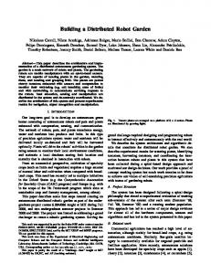
[8] Figure 9. Robot Rato is giving a tour in “Palacio de Congresos y Exposiciones de Galicia”, Santiago de Compostela (Spain) for the xuventudeGalicia.net event in March 2008. [9]
The waiting behavior is activated for example when the robot is waiting for visitors. Once the visitors get close to the robot they are invited for a tour and if they get closer the robot heads shows a happy face and starts the tour. Besides the behaviors, several facial expressions are activated in different points of the higher level Petri Nets. VI. RESULTS AND CONCLUSIONS We have used the system described in this paper in a mobile robotic guide that was working for three days (march 2008) in the “Palacio de Congresos y Exposiciones de Galicia”, Santiago de Compostela (Spain) for the “Xunventude Galicia Net” event. For this application a modified B21 model shown in fig 9 was used. In this kind of application the environment is a set of stands, most of them mounted the day before. Furthermore, some of the tasks are not fully defined until a few hours before the starting of the event. Therefore, a tool like RoboGraph to quickly create, change and debug tasks becomes necessary. Behaviors that associate events to head expressions and actions are also easily changed as we stated before. For this year’s edition (2008), we have used the robot RATO with the head described in this paper and the acceptance was much better. People tried to interact with the robot, they even expected human-like capabilities and talked to the robot expected to be answered. Some of the visitors tried to find out what actions would make the robot change his facial expressions and say different things. ACKNOWLEDGMENT We would like to thank all the people that have influenced this work. Especially, Javier Perez Castro who designed the previous robot head, base of this work. Also to Reid Simmons for his helpful advices about the use of IPC and Dr. Mónica Cid for her help with the English grammar.
[10]
[11]
[12]
[13]
[14]
[15]
[16]
[17]
[18]
[19]
[20]
[21]
J. Bates. The role of emotion in believable characters. Communications of the ACM, 1 B. Blumberg. Old Tricks, New Dogs: Ethology and Interactive Creatures. PhD thesis, MIT, 1996. Breazeal, C. (2000), "Sociable Machines: Expressive Social Exchange Between Humans and Robots". Sc.D. dissertation, Department of Electrical Engineering and Computer Science, MIT. S. Li, M. Kleinehagenbrock, J. Fritsch, B. Wrede, and G. Sagerer.”BIRON, let me show you something”: Evaluating the interaction with a robot companion. In Proc. of the IEEE Int. Conf. on Systems, Man, and Cybernetics (SMC), 2004. O. Rogalla, M. Ehrenmann, R. Z¨ollner, R. Becher, and R. Dillmann. Using gesture and speech control for commanding a robot assistant. In Proc. of IEEE Int. Workshop on Robot and Human Interactive Communication (ROMAN), 2002. R. Stiefelhagen, C. F¨ugen, P. Gieselmann, H. Holzapfel, K. Nickel, and A. Waibel. Natural human-robot interaction using speech, head pose and gestures. In Proc. of the IEEE/RSJ Int. Conf. on Intelligent Robots and Systems (IROS), 2004. T. Tojo, Y. Matsusaka, T. Ishii, and T. Kobayashi. A conversational robot utilizing facial and body expressions. In Proc. of the IEEE Int. Conf. on Systems, Man, and Cybernetics (SMC), 2000. S. Thrun, M. Bennewitz, W. Burgard, A.B. Cremers, F. Dellaert, D. Fox, D. Haehnel, C. Rosenberg, N. Roy, J. Schulte, and D. Schulz. MINERVA: A second generation mobile tour-guide robot. Proc. of the IEEE International Conference on Robotics and Automation (ICRA'99), 1999. Bennewitz, M.; Faber, F.; Joho, D.; Schreiber, M.; Behnke, S. Towards a humanoid museum guide robot that interacts with multiple persons. International Conference on Humanoid Robots, 2005 5th IEEE-RAS Volume , Issue , 5-7 Dec. 2005 Page(s): 418 – 423 K. Berns, C. Hillenbrand, K. Mianowski The Mechatonic Design of a Human-like Robot Head 16-th CISM-IFToMM Symposium on Robot Design, Dynamics, and Control (ROMANSY) – 2006 E. P. Domonte, J. P. Castro, J. L. Fernández, R. Sanz. Diseño de una Cabeza Robótica para el estudio de procesos de interacción con personas. Proceedings of the XXV Jornadas de Automática 2005. Kim, H., G. York, Burton, E. Murphy-Chutorian, and J. Triesch (2004). Design of an Arthropomorphic Robot Head for Studying Autonomous Development and Learning, Proc. Int. Conf. On Robotics and Automation, ICRA 2004, New Orleáns, LA, USA. Mori, Masahiro (1970). Bukimi no tani [the uncanny valley] (K. F. MacDorman & T. Minato, Trans.). Energy, 7(4), 33-35. (Originally in Japanese) MacDorman, Karl F. & Ishiguro, H. (2006). The uncanny advantage of using androids in cognitive science research. Interaction Studies, 7(3), 297-337 Hanson, David, Bergs, R., Tadesse, Y., White, V., Priya S. "Enhancement of EAP Actuated Facial Expressions by Designed Chamber Geometry in Elastomers." In Proc. SPIE's Electroactive Polymer Actuators and Devices Conf., 10TH Smart Structures and Materials Symposium, San Diego, USA, 2006 R. Bonasso, D. Kortenkamp, D. Miller and M. Slack, “Experiences with an architecture for intelligent, reactive agents”. Journal of Artificial Intelligence Research Vol 9(1), pp: 237-256, 1997 M. Montemerlo , N. Roy, S. Thrun, “Perspectives on Standardization in Mobile Robot Programming : The Carnegie Mellon Navigation (CARMEN) Toolkit”, Proceedings. 2003 IEEE/RSJ International Conference on Intelligent Robots and Systems, (IROS 2003). 27-31 Oct. 2003. Vol. 3, pp: 2436- 2441 A.R. Diéguez, J.L. Fernández, R. Sanz, “A global motion planner that learns from experience for autonomous mobile robots”, Robotics & CIM Vol. 23 pp: 544–552 (2007), Ed. Elsevier. J.L. Fernández, R. Sanz, J.A. Benayas and A.R. Diéguez, “Improving collision avoidance for mobile robots in partially known environments: the beam curvature method.” Robotics and Autonomous Systems. vol. 46, pp. 205-219, April 2004. J. L. Fernández, Maria J. Souto, Diego P. Losada, R. Sanz, E. Paz. “Communication framework for sensor-actuator data in mobile robots”. Proceedings of the 2007 IEEE International Symposium on Industrial Electronics, pp:1502-150. ISBN: 1-4244-0755-9. Joaquín López, Rafael Sanz, Enrique Paz and Carlos Alonso. “Using hierarchical binary Petri nets to build robust mobile robot applications: RoboGraph”. IEEE International Conference on Robotics and Automation, 2008. To be published in the conference proceedings.