Information and communication management in building design case studies S. Scheer1 , J. Mikaldo Jr2 1
Civil Engineering Research Centre, Federal University of Paraná, P.O. Box 19011, Curitiba, Paraná, BRAZIL, CEP 81531-980; PH (55) 41 3361-3218; FAX (55) 41 3361-3436; email:
[email protected],
[email protected] 2 Graduate Program of Construction Engineering, Federal University of Paraná, P.O. Box 19011, Curitiba, Paraná, BRAZIL, CEP 81531-980; PH (55) 41 3361-3218; FAX (55) 41 3361-3436; email:
[email protected] Abstract This paper presents a multiple case study on building design process with the implementation of IT tools (project extranet, two- and three-dimensional modeling and physical interference analysis system). It aims to investigate 3D harmonization design process and information and communication management during the building design process. The use of a web environment facilitated the communication of the technical teams, improving the information flow among them with the optimization of the entire project development. The management planning tasks involved action and communication plans development. The action plans were helpful for task workflows and schedules definition, timing for hiring teams, team members’ training, certification and responsibilities. Moreover, they were crucial to the integration of the different design disciplines in order to minimize interferences and improve the harmonization of the whole building design. The communication plan proved to be crucial in maintaining the teams’ dynamics as a whole, and the information flow for the entire process.
Introduction The globalization of the economy is currently being pushing the business competitiveness even for small and medium enterprises such as the regular building construction enterprises. According to Porter (1993), the companies become competitive with direct intervention in cost, quality, flexibility, time and innovation issues. In this context, the design phase in the construction enterprises certainly is fundamental and is a common sense that more investment in the design phase is a good path for construction enterprise cost reduction. Moreover, the introduction of Internet-based technologies (such as extranets) and other CAD tools (CAD3D/4D/nD, mobile computing) begun to make inroads into the construction industry practice (Feijó et al., 1996; Aouad et al., 2005; Abduh and Skibniewski, 2004). As a consequence, the building design practitioners ought to revise their roles as knowledge managers primarily to gain new knowledge and skills (Husin and Rafi, 2003). Architects and engineers must continuously revise their strategic mission, skills, technology and knowledge to remain competitive. This paper presents the design coordination task named ‘harmonization’ as a necessary activity during the design phase with intervention in the Porter’s cited issues. In addition, it provides case studies data and analysis for investigating 3D harmonization processes and information and communication management during the building design activities. An extranet was the main IT tool used for the communication among design team members. The management tasks were improved through action and communication plans development, very helpful in several tasks as in workflows and schedules definition, hiring teams, training, and certification. Design Harmonization A building designer, architect, or building engineer may produce designs for all types of buildings in small projects while larger projects will often need other engineers and consultants in structural, mechanical and electrical engineering. As building projects are getting larger and more complex, modern trends in building design need professionals trained broadly in many disciplines. Korman and Tatum (2006) describes a research that looks for an effective mechanical, electrical, and plumbing (MEP) coordination through the development of a technology that integrates a number of knowledge bases into a knowledge-based system. The MEP coordination requires recalling and integrating knowledge regarding design, construction, and operations and maintenance of each one of the MEP systems. Currently, this coordination process involves a series of meetings where representatives from each MEP trade overlay drawings of their respective systems to detect and eliminate numerous types of interferences. The harmonization could be seen as a building design attribute in which the system components occupy their own spaces without any conflict or mutual physical interference. In other words, design harmonization is the coordination activity that intends to ensure compatibility among all design disciplines. Furthermore, this activity intends to reach an integrated solution for the entire building design that leads to a feasible enterprise.
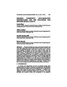
Research Method Three case studies were conducted for building design and construction enterprise coordination (from 2005 to mid 2006). The first case is reported in Scheer et al. (2007) and the complete research report can be found in Mikaldo Jr. (2006). The data were collected through direct observation and measurements with the help of a project extranet (http://www.cesec.ufpr.br/sigep), documental analysis (building design plants and other documents, harmonization registers, etc), interviews and questionnaires. The harmonization process analysis was cross developed using collected data and interviews with the stakeholders. In addition, design management process was improved by action and communication plans that were also analyzed. First Case Study – Traditional CAD2D Design Harmonization. The first case study was a building for banking purposes with 1200 square meters built area. It has reinforced concrete structure with masonry panels externally and dry-wall internally. The design team had fifteen different specialty professionals: one architect, nine civil engineers, one electrical engineer, one mechanical engineer, two academic advisors, one undergraduate student, one contractor firm, and the client company. There were very intensive collaborative work using the extranet. The design requirements and tasks were defined and adapted to: existent client guidelines; design harmonization guidelines from the local construction owner’s union; and professional experience of the project manager team (as in the other case studies). The designs were developed in 2D and the harmonization in traditional CAD layer superposition. Together with a checklist, other information mechanisms (information and interference matrices and communication plan) were used to obtain compatible information not shown in the design plants, as described in Scheer et al. (2007). Second and Third Case Studies – Fully 3D Design Harmonization. The second studied construction enterprise was an automotive center with 2000 square meters built area. And the third case study was a thirteen-story residential building with 3500 square meters. Both had reinforced concrete as structural system, stonewall panels made externally and internally of drywall. The entire design for both buildings was developed in 3D using Brazilian integrated CAD systems developed by AltoQI (http://www.altoqi.com.br). The harmonization process was developed with the help of a physical interference analysis software (Figure 1) developed by the same software company, and a checklist as well. This system permits software integration by using a proprietary data file format compatible with the other 3D design dimensioning systems for structural, piping systems (water and sewage) and electrical specialties. The physical interferences integration in the 3D model became “more visible” and easier to be understood. The harmonization coordinator sent interferences list to the designers in order to be analyzed and consensus decisionmaking for solution. In these study cases, it was used a design process flow that is presented in Scheer et al. (2007). Despite of the predicted three-harmonization phases, during the research there were only two distinct harmonization activities: the first one was during the preliminary design, and the second during the final basic design.
Figure 1. 3D harmonization view of structural, plumbing and electrical designs. Information and Communication Management The project extranet. An extranet developed by the research group was used to serve as a central file repository and the main communication system. It implements a central database environment with a three-layer paradigm for projects (my projects, my activities, and my tasks). The interface permits the users to visualize how, when, and which information will be at their disposal and is exchangeable; to promote communication through information transfers (any changes can be automatically communicated by e-mail, mural and repository of files with easy versioning control). Training and action plan. An action plan containing the necessary information for the development of the contracted design works was prepared. This action plan was submitted to those who were involved during extranet training in order to help in the comprehension of the collaborative work process, task scheduling, workers’ contracts, training activities, team member’s role, duties and responsibilities, and finally, the strategy to produce design compatibility and harmonization. Questionnaires. Two questionnaires were handed out after the workers’ training in order to establish the profiles of the fifteen professionals involved in the first case study, as well as their expectations about the system’s usage. The user profile revealed that in the project team, while more than 73% of architectural or engineering design professionals had less than five years experience, they had high IT skills, whilst only two of them (13%) had little knowledge about extranet usage. Information and interference matrices. The data and information integration was achieved through the extranet adoption with an unique shared database for the entire project. Moreover the matrices of information and interference concept (Andery et al., 1998) could also be applied to help the construction’s success in the design phase. Using hypertext functionalities it was possible to create links from matrix cells to page documents, thus helping the operation and visualization. The information and interference matrices were updated and uploaded to the extranet folders by the project manager or harmonization supervisor. The matrices’ information could be obtained from the client requirement briefing, stakeholders’ virtual communication area (available on the extranet), and physical interference report among the different design disciplines. Samples of these matrices are illustrated in Tables 1 and 2.
Table 1. Information Matrix Sample (adapted from Andery et al., 1998) Destiny
Origin
Design discipline Architecture
Architecture
Structures
Building usage plan for load evaluation Hydraulic pipe dimensions and bathroom
Facilities
Structures
Facilities
Others
Structural system solution to guide the architectural preliminary studies
Fire department regulations and available room space Water reservoir and structural loading
...
...
Which beams must/can have piping perforations?
...
The information matrix is in a structured and concentrated form to show all the necessary information for each specific design development. In the other hand, the main objective of the interference matrix was to detect and organize physical interference that could produce re-work and higher costs for the building enterprise (Sample shown in Table 2). Table 2. Interference Matrix Sample (adapted from Andery et al., 1998) Design discipline Architecture
Architecture
Structures
Facilities
Others
X X
Facilities
X
X
Pipe and window interference Holes in structural elements X
...
Structures
Column and window interference X
... ...
Communication plan. The communication plan defines the interested members (receivers), content (requirements), communication tools, format, frequency, and transmitters. The information and interference matrices were used to obtain the communication plan. The design product (document/drafting), producer (transmitter), and where the information will be applied (receiver) is shown in this type of plan. The first activity for plan construction was carried out during the design team’s training. Thereafter, a communication plan for every design phase was prepared. Results and Analysis Harmonization process. Table 3 presents a comparison between the three case studies and also some data collected during the interviews. Project member expectations. All the extranet users indicated the system’s usage relevance for themselves and for their companies. In regard to the anticipated success of the system, most answers did not expect a guaranteed success for system’s usage. Besides the ease of use, financial support for the initial experiment and user’s enthusiasm, there was some doubt about the availability and understanding of each
project team member. The questionnaire answers showed moderate optimism about the expected goals. It contained questions about technical and business goals, user requirements, and the time needed for implementation. And the changes brought about by the system’s usage were considered favorably in most of the answers given. The obtained results are summarized in Table 4. Every aspect or functionality of the extranet system was analyzed critically according to its performance and the expectations of the agents involved. Every building project has a unique set of program goals and technical requirements that demand assembling all the stakeholders and a multidisciplinary professional team. Each design discipline has a different set of skills, professional standards, and issues that drive how they operate in the building process. Traditionally, many disciplines provide a specialized technical service that is not always well coordinated with other aspects of the project. Table 3. Short Comparative Analysis of 2/3D Harmonization (Scheer et al., 2007) Harmonization elements
Case Study 1: 2D Harmonization
Case Studies 2 and 3 : 3D Harmonization
Technical capacity for design development using CAD
The designers need only CAD2D use knowledge
Technological infrastructure (software)
The harmonization can be done using superposition of CAD2D layers
Information flow
The project extranet proved to be very useful for all the participants. The design harmonization was understood as a necessary activity for the building design activities.
The designers need dimensioning good skills and CAD3D modeling knowledge. The interference analysis system (low-end) permits integrated 3D harmonization process for structural, electrical and plumbing designs (despite of proprietary format). It is also possible to use 2D modeling for 3D modeling generation in other CAD systems, of course. The project extranet proved to be very useful for all the participants. The 3D interference analysis system also facilitated the contractors and client/owner understanding. Harmonization was important to get cost reduction, help construction logistics, and visualize a 3D integrated model. The same as 2D harmonization. In addition, 3D harmonization allowed more than two discipline design comparison at the same time with automatic interference detection.
Client/Owner valorization
Advantages in terms of costs, waste of material and rework
All the participants understood harmonization presented advantages such as frequent interaction among all designers (extranet). They agreed about the necessary design manager team participation in the process.
Table 4. Web Project Management Functionality Evaluation Aspect Competence of the team Project Process
Performance Evaluation To break the barriers and resistance as well as the use of the extranet and integrate the team members. The general flow diagram helped design team in the process comprehension and interaction manner.
Communication and information flow feasible; provisions availability; process dynamics verified; on-line system (chat or videoconference) may be useful; usual and useful e-mail notification is the most usual and useful. All communication files were storaged in the extranet. Good Collaborative environment and extranet evolution: server performance (hardware provided); access mechanisms for general and profile control; information flow and controls; time for control of revision changes upload/download; and, in version management (document rules) The managers helped to elaborate an integrated project, following Process Management design and designers requirements and demands. The integration allowed fast decision making and communication to all members. Transparency and comprehensive responsibilities distribution. In the identification of risks, development of solutions and Risk Management monitoring of the process (risks and responses). Plan of Communication
Conclusions As expected, the 3D harmonization process presented advantages over the traditional 2D layer superposition. In the other hand, it depends on technological solution (3D interference analysis system) and more skilled professionals. The design harmonization plays a very important role to guarantee the compatibility for each part of the whole building design. Consequently, beyond physical interference detection among different building components, the design manager team could use a collaborative environment in order to search the best building design solution. In addition, an interactive approach to the design process is required to create a successful building design. All the people responsible for the building design need to interact closely throughout the design process. The client, architects, engineers, contractors and consultants need to attend and understand the design issues and concerns of the other involved parties. The project extranet together with the action and communication plans proved to be useful and mandatory to accomplish with it. Moreover these information and interference matrices available through the extranet document repository allow control over a transparent and very intensive interaction among the designers. The matrices can be incremented with registration of the design expertise improved during the process or due to necessities. The establishment of an action plan created a consistent framework for the project’s process. In this framework all the process activities of the each specific design through the web were identified, analyzed and planned in relation to the technological platform and collaborative environment. The previous increase in all activities related to the project and the planning, making it feasible in a virtual environment, was extremely useful in the visualization
of problems, which constituted part of the barriers that had not allowed an efficacious plan in earlier experiments. This helped to realize the solution and detach, in a clear and distinct manner, the processing failures originated in the technological infrastructure or by its operation in a collaborative environment. During the research described, the need for a proper project process applicable to an Information and Communication Technology (ICT) tool – collaborative project environment/extranet – was noted. Thus, the search continues for the adaptation of the collaborative environmental dynamics for the agents and their professional routines and vice-versa. Finally, the actual trend in building design continues to be toward full integration of data and processes regarding the previously separated design specialties. Acknowledgements The authors would like to thank the support for the case studies by the construction companies and the Brazilian software developer company AltoQI. References Abduh, M.; Skibniewski, M. (2004) “Electronic networking technologies in construction”. Journal of Construction Research, 5(1), 17-42. Andery, P. R. F.; Vanni, C. M. K.; Gomes, A. M. (1998) “Análise de Falhas Aplicada a Compatibilização de Projetos em um Obra Predial”. Latin American Congress on Technology and Management in Building Construction, São Paulo. Proceedings. Aouad, G., Lee, A. and Wu, S, (2005) “From 3D to nD modeling”. Journal of Information Technology in Construction (ITCon), 10(-), 15-16. Feijó, B.; Gomes, P. C. R.; Bento, J.; Scheer, S. (1996) “CAD for Process Innovation in the Construction Industry”. Structural Eng. and Mechanics, Taejon, 4(6), 717-729. Husin, R.; Rafi, A. (2003) “The impact of Internet-enabled computer-aided design in the construction industry”. Automation in Construction, 12(4), 509-513. Korman, T. M.; Tatum, C. B. (2006) “Prototype tool for mechanical, electrical, and plumbing coordination”. Journal of Computing in Civil Engineering, 20(1), 38-48. Mikaldo Jr, J. (2006) “Estudo comparativo do processo de compatibilização de projetos em 2D e 3D com o uso de TI”. Master´s Dissertation, Graduate Program in Construction, Federal University of Paraná, Brazil. 151p. Porter, M. E. (1990). The Competitive Advantage of Nations. New York: Free Press. Scheer, S., et al. (2007) “The necessary background for implementing and managing building design processes using web environments”. Journal of Information Technology in Construction, 12(-), 193-206.