Czech Technical University in Prague Faculty of Electrical Engineering Department of Computer Science & Engineering
Building Secure Information Systems Dissertation
Study Branch: Information and Computer Science Supervisor: Doc.ing. Karel Richta, CSc. Postgraduate Student: Suzana Stojaković- Čelustka, MSc.
Prague, 2000.
Abstract The Part I of the thesis describes security problems in today’s information systems. They are numerous because today’s information systems were not built with security requirements from the beginning. There are also many protection tools, which are designed to protect more or less efficiently information systems from malicious activities. However, even the best protection systems have their vulnerabilities. The security weaknesses include the very basics of today’s computing and network systems, such as binary logic and von Neumann’s architecture. The universality of von Neumann’s architecture, which is very convenient from the user’s point of view, is inconvenient regarding security requirements. It is important to stress that anything, which can be programmed, may be programmed to perform malicious activities in the system and it is very difficult to discern such an attempt from the “normal” activities before some damage is done. Binary logic is a basic of today’s computing, i.e. everything is performed through the sequences of zeros and ones. While it makes computing easy, it is an obstacle considering security requirements for exact pattern recognition. Although there are the methods to circumvent this inconvenient bound, it still remains the problem, which can be solved in satisfactory way by changing the binary logic to multivalued logic. Having in mind these two major obstacles to information systems security, in the Part II of the thesis some other possibilities in the logic and architecture are offered so to have security requirements built from the start in information systems. The Part II describes the ways on how to build secure information systems. The suggested basis of the secure information system is an intelligent security system. The term "intelligent" in the name of this security system does not indicate that the other security systems are non-intelligently constructed or designed. It simply means that this security system should have some intelligent capabilities such as the ability to learn or understand from experience, the ability to acquire and retain knowledge, the ability to respond quickly and successfully to a new situation, the ability to make proper decisions, etc. The main goal of so proposed intelligent security system is to emulate an intelligent reaction to any suspicious action, which might occur in the information system. For that purpose the prototype with working name Nisan was developed and it is presented in detail in this thesis. It was shown that realization of theoretical concept is possible and that it gives satisfying results, even in this early phase of development. It is shown that this intelligent system can be implemented in various kinds of current and future architectures considering corresponding advantages and constraints. It is supposed that realization of such an intelligent security system in any kind of information structures would be great advantage in the security of information systems.
Acknowledgements In the first place, I would like to thank to my mentor, professor Dr Karel Richta, for his engagement, valuable suggestions and great support, which helped me in writing this thesis. I would also like to thank to professor Dr Melichar, who gave me opportunity to perform my somewhat unusual research on Department of Computer Science and Engineering, Faculty of Electrical Engineering, Czech Technical University of Prague. I must make special mention of professor Dr Kolar's final suggestions on the ways of how to finish this thesis for which I am especially grateful. I am also grateful to all professors and staff of Department of Computer Science and Engineering for their advises and patient tolerance of my sometimes dangerous experiments with computer viruses and other types of attacks. I would also like to thank to professor Dr Brunnstein, head of Virus Test Center on Faculty of Informatics, University of Hamburg, for allowing me to perform additional experiments at his Department. Thanks go also to Vesselin Bontchev (now at Frisk Software International) for his helpful support. Special thanks go to the group of people who are not only experts in information security field, but are also my dear friends, who were helpful during all these years: Jon Freivald, systems architect and network engineer at Total Computer Systems, Ltd.; David M. Chess, research staff member of IBM Tomas J. Watson Research Center; Yaron Y. Goland, software architect at Microsoft Corporation; Jon David, senior editor of Computer & Security; Staale Fagerland, computer virus analyst at Norman Data Defense System AS; David Harley, Support and Security Analyst at Imperial Cancer Research Fund; Roberto Reymond from IBM Global Services, NWSM Security, IBM-Italy; Gord Hama of Royal Canadian Mounted Police; Paul Ducklin, head of research in Sophos Plc.; Tim Martin from Department of Renewable Resources at University of Alberta; Padgett Peterson; Rob Slade; Wallace Hale; Sarah Gordon and Richard Ford. Many thanks I owe also to Damir Delija from SRCE (University Computing Center in Zagreb), Nevenko Bartolincic from CARNet (Croatian Academic and Research Network) and to Peter J. Mercier from US Naval Criminal Investigative Service, for their helpful suggestions. My family provided me with support, love, friendship, advice, and untold other type of assistance to my progress in this matter, and without naming them each, I would like to thank them.
Contents INTRODUCTION.......................................................................................................I-1
Part I 1. INFORMATION SYSTEMS................................................................................. 1-1 2. MISUSE OF INFORMATION SYSTEMS............................................................2-1 3. PROGRAMMED THREATS.................................................................................3-1 4. PROTECTION OF INFORMATION SYSTEMS..................................................4-1 5. VULNERABILITIES IN PRESENT PROTECTION SYSTEMS.........................5-1 6. SUMMARY AND CONCLUSIONS OF PART I..................................................6-1
Part II 7. WHAT IS SECURE INFORMATION SYSTEM.................................................7-1 8. AN ARCHITECTURE FOR INTELLIGENT SECURITY SYSTEM..................8-1 9. MODELING AN EXPERT SYSTEM...................................................................9-1 10. IMPLEMENTING AN INTELLIGENT SECURITY SYSTEM.......................10-1 11. BUILDING SECURE INFORMATION SYSTEMS.........................................11-1 12. SUMMARY AND CONCLUSIONS OF PART II............................................12-1
Part III 13. SUMMARY, CONCLUSIONS AND FURTHER WORK................................13-1 APPENDIX A - GLOSSARY OF USED TERMS....................................................A-1 APPENDIX B - PREVENTION METHODS............................................................B-1 APPENDIX C - SOURCE CODE OF PROTOTYPE NISAN..................................C-1 BIBLIOGRAPHY......................................................................................................II-1
Introduction
INTRODUCTION MOTIVATION Information security is very complex field of research with a lot of unknown and unexplored areas. Yet, it is an important field to explore. My own interest in this field started ten years ago when I first met computer viruses. The problem of selfreproducing threats to information integrity and availability was a challenge for me for many years. By time I got acquainted with other information security problems, such as break-ins, denial of service attacks, etc. From the first moment protection of the information systems was the most important challenge, which motivated me to persevere in this type of work.
PROBLEM STATEMENT First of all, I would like briefly to introduce some of important questions such as: what is information, what is information age, what is and why we should have information security.
What is Information? It is not an easy task to define what is really meaning of the term "information". Intuitively, information is sequence of symbols, which have some meaning to the person receiving it. People communicate by exchanging information among them. The importance of information can be valued quantitatively, depending on the context. Sometimes information can be valued through monetary amount and that aspect makes exchange of information very important in today's human society.
Information Age The human society is undergoing a fundamental transformation: from an industrial society to the information society. Information age technologies increasingly pervade all industrial and societal activities and are accelerating the globalization of economies. World's industrial competitiveness, its jobs, its quality of life and the sustainability of growth depend on it being at the leading edge of the development and take-up of information age technologies. At the same time, the technologies underpinning the development of the information society are in rapid evolution. Advances in information processing and communication are opening up exciting new possibilities. There is a shift from stand-alone systems to networked information and processes.
I-1
Introduction
Information Age and the Internet In the age when communications and media have tremendous impact on our lives, information and information technologies are becoming more and more important. Internet as a “network of networks” is becoming the most popular media for the information transfer. Neither information nor control over them is reserved for a small number of experts. In the age of information everybody needs and uses information. That is why Internet is not only a tool of the modern age, it is also its symptom. Fast information exchange in almost every segment of our daily life helped the Internet to move on from an oddity to the most popular medium. The Internet is growing faster than previously thought. Internet’s user population is growing 175 % per year [69]. The Internet is going commercial. Saving money and energy is an essential part of every business. That is why electronic commerce and on-line money making is becoming more and more popular. There is a rapid expansion of the Internet with commercial users such as companies, banks, brokerage companies, airlines, retail establishments, and most computer hardware and software companies. It also includes personal accounts held by users of various on-line service providers such as America On-line, Prodigy, CompuServe etc. The explosive growth of global computer networking is revolutionizing business and economy and the way individuals shop for products and services and engage in entertainment and education.
Information Security Security has always been an important part of our everyday life. Throughout the history people have tried to protect their property and privacy. With the advance of technology and growth of industry it has become an even more important aspect.
Why information security? Even in the age when there were no computers and no Internet information, the control over information was a significant factor in the prosperity of the business. Now, more than ever, since business is more and more relying on information technology it is important to protect that information. The same is true for doing business on the Internet. Every business must be secure and reliable to be successful. One has to find ways to prevent information security breaches and allow performing secure, reliable transactions on the Internet. A November 1997. report released by the Permanent Investigations Sub-Committee of the US senate estimated that business lost around US $ 800 million in 1995.
I-2
Introduction through break-ins to computer systems at banks, hospitals and other large businesses. [69] The study found variation in the types of attacks, confirming fears that information security breaches are no longer the domain of relatively harmless, curious hackers, but are increasingly being conducted by disgruntled employees, professional criminals and industrial spies. These findings indicate a direct correlation between the level of security penetrations and the level of workplace dependence on information technology. Therefore, computer crime is expected to escalate in industries increasing their reliance on high information technology.
What is information security? The world of business is a significant information security challenge. It is not an easy task to protect and control information. One has to deal with such complex issues as computer crime, data privacy, copyright, etc. The ultimate goal is to have a secure, reliable and correct information. Confidentiality, integrity and availability of the information typically characterize the information security. Confidentiality means controlled release of information and protection from unauthorized access. Integrity represents the control of modifications and correct and authorized information transactions. Availability means that information is available when required and that denial of service will not occur. Information technology has enabled organizations to work more effectively, but alongside the benefits arise also security risks and threats to confidentiality, integrity and availability of information. To protect information resources of an organization it is necessary to recognize the threats and come to grips with them. Threats range from human error to theft, vandalism, computer crime, natural disaster, to name but a few. For example, threats to confidentiality arise from cracking, stealing information, fraud by internal and external access. Threats to integrity represent a processing of incorrect data due to equipment failure, software and human errors, malicious damage and fraud. Threats to availability arise due to equipment failure or overload, denial of service, malicious damage, theft of resources, etc. New technologies have unfortunately revealed new vulnerabilities. Portable computing, telecommuting and remote access services have spread the problem way beyond the individual organizations. The addition to the problem is also a rapidly changing marketplace on which trends appear and disappear very quickly. This circumstance causes the immature technologies to be implemented before their effect on security has been examined and understood. Countermeasures include reducing the vulnerabilities of a system and the threats to the system. It is necessary to have the defense against the threats by reducing likelihood of the threat happening and the impact of the potential security incident by limiting its effect. Naturally, it is very hard to ensure a complete and foolproof security system. There is no single technical solution yet, which would assure absolute information security.
I-3
Introduction The information security system must always integrate various methods of protection, ranging from physical security and administrative measures to implementation of sophisticated protection tools.
RELATED WORK Most of my articles and lectures are related to computer viruses problems [64], [65], [68] as well as my M. Sc. thesis [31]. My minimal thesis [67] deals with that problem too. I have spent a lot of time on research in computer virus behavior and possible ways of protection. However, my work extends to other ways of information security threats as well. Since 1993. I was also researching various ways of break-ins on Department of Computer Science & Engineering of Czech Technical University in Prague. In the late 1993. I was a guest of Faculty of Informatics in Hamburg where, after two weeks of experimental work, I had a lecture about vulnerabilities in Internet services [66]. Since 1994., I am an active member of the IFIP working group 9.6., which concerns the problems of information technology misuse and the laws. In the period May, 1997. – November, 1998. I was actively working as a network security consultant for Croatian Academic and Research Network (CARNet). My duties included managing CARNet CERT (Computer Emergency Response Team) where I could implement my theoretical knowledge of vulnerabilities and protection measures in practice. During that period I have also prepared several courses and lectures about information security, as well as an article for FIRST (Forum of Incident Response Teams) 1998. Conference [69]. Working as a security consultant I have found an interesting fact concerning the age of attackers to information systems. It appeared that in an academic network perpetrators were mostly teenagers, with a little knowledge about information systems themselves. Working currently in high school educational system, from where most attackers come from, I am trying to teach my students not only about information technology basics, but also about ethical behavior in an information world of today. I believe that teaching young people how to use information systems properly and ethically can prevent future information technology misuse.
CONTRIBUTION OF THE THESIS Although my previous work was in great extent related to computer viruses, that type of threats to information security is not the only one considered in this thesis. I am trying to cover in the thesis as wide area as possible. The main problem in achieving this is that in today’s information security field there is neither uniform formal apparatus nor terminology, which could consistently cover such a complex area. I tried throughout this thesis to preserve consistent formalism to describe very various topics.
I-4
Introduction A model of adaptive automated protection system is introduced in the thesis. It does not exist yet, except as a concept. It is ultimate model, which has sense in today’s information systems. Yet, even this model contains several vulnerabilities, which are clearly stated. General problem is, however, how to build secure information systems in the future and the thesis tries to gives some answers to that problem. The main assumption is that today’s systems are weak from that point of view and not built with the security requirements from the beginning. The aim of the thesis is to offer some other possibilities in the logic and architecture of computing/information systems so to have security built in from the start. It is a difficult task to grasp with and the thesis certainly cannot give all possible solutions. The solution offered in this thesis is the concept and working prototype of an intelligent security system. That concept is the result of practical work on security problems during the years and its prototype is developed in hope to significantly improve the security of the information systems today and in the future.
ORGANIZATION OF THE THESIS This thesis is divided into three parts: Part I, Security Problems in Today’ s Information Systems This part introduces the security problems and methods of protections in today’s information systems and summarizes the vulnerabilities of present protection systems. Chapter 1, Information Systems, presents the concept of information, information system and computing system, as well as of information networks and Internet. Chapter 2, Misuse of Information Systems describes how the information systems can be attacked. Chapter 3, Programmed Threats, describes some of the most frequent programmed attacks Chapter 4, Protection of Information Systems, describes methods of protection, prevention, non-adaptive protection systems and adaptive automated protection systems as ultimate protection solutions in today’s information systems. Chapter 5, Vulnerabilities of Present Protection Systems, provides an overview of the vulnerabilities of today’s protection systems and inherent security holes in today’s information systems. Chapter 6, Summary and Conclusions of the Part I, gives the short summary and conclusions of the first part.
I-5
Introduction
Part II, Building Secure Information Systems This part looks at the ways how to build future information systems so to obtain maximum security. Chapter 7, What is Secure Information System?, presents the semantic definition of information, discusses what is secure information and gives the definition of secure information system. Chapter 8, An Architecture for Intelligent Security Systems, introduces the concept and the architecture of an intelligent security system. Chapter 9, Modeling an Expert System, introduces the theoretical model for the expert system of an intelligent security system. Chapter 10, Implementing an Intelligent Security System, presents the prototype of an intelligent security system. Chapter 11, Building Secure Information Systems, describes the ways for building secure information systems with an intelligent security system. Some other aspects of information security, such as human interface and privacy protection, are briefly introduced. Chapter 12, Summary and Conclusions of the Part II, gives the short summary and conclusions of the second part. Part III, Summary, Conclusions and further Work, This part contains only one chapter (Chapter 13) which gives a summary and conclusions of the thesis as well as directions for further work. Bibliography contains a listing of resources used for this thesis. Appendices: Appendix A – Glossary of Used Terms Appendix B – Prevention Methods Appendix C - Source Code of Prototype Nisan
I-6
PART ONE
Security Problems in Today's Information Systems
Chapter 1
Information Systems
1. INFORMATION SYSTEMS 1.1. Concept of Information Suppose that some event, which realization is uncertain, occurs. It is not predetermined and is not known in advance. When that event happens and when we know something about it, intuitively we consider that we have received some information. In the essence of the very concept of information there is some uncertainty included, which is eliminated by receiving the information. Anyway, even before the event happens, the observer is formulating his or her expectation about the realization of the event. The mentioned concepts: uncertainties, expectation, assumptions, related to the concept of information, lead us to its connection to probability theory. The information could be represented by functional relation of probability, under assumption that information increases when probability of the event decreases and vice versa. Since information eliminates uncertainty, then to lower probability would correspond greater uncertainty and smaller expectation. The suitable definition of information might be that information represents the degree of freedom in choice of message from the set of all possible messages. Unit of information is called “bit” (an abbreviation of binary digit). The quantity of information of 1 bit is included in the message, considering that the degree of freedom was the choice from two possible messages (0 or 1). Semantic aspect of information, which concerns the contents or sense of the message is excluded from this concept of information. It will be discussed later in Part II of the thesis.
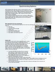
1.2. Information System General information system consists of the source of information, encoder of information, communication (transmission) channel, decoder and receiver of information as it is shown on the Figure 1.2.1. SOURCE
ENCODER
TRANSMISSION CHANNEL
DECODER
RECEIVER
Figure 1.2.1. General information system The source of information can be described by set of pairs {xi, p(xi)}, i=1,2,...n, where xi denotes one of n messages, which might appear on the source, while p(xi) denotes probability of appearance of that message. The quantity of information can be represented as in [28]:
1-1
Chapter 1
Information Systems
I (xi) = - log2 p(xi) = -ld p(xi)
(1.2.1)
The average quantity of information on the source is [28]: n
I ( X ) = − å p( x i )ldp( x i ) = H ( X ) i =1
(1.2.2) The average quantity of information is the quantity of information, which is needed in average to determine any individual symbol or message from the set X of all possible symbols or messages which are transmitted through communication channel. The quantity I(X) is also called the entropy of discrete stochastic quantity X and is designated as H(X) [28]. Quality of communication can be expressed via quantity of information flow, which can be transmitted through communication channel with errors (noise). It is the quantity of information, which belongs to the set of received messages {Y} and is uniquely related to the set of sent messages {X}. Quantity of information transmitted through the communication channel with errors is called transinformation and can be expressed as [28]: I (X;Y) = I(X) – I(X/Y) = I(Y) – I(Y/X)
(1.2.3)
The pairs {xi,p(xi)}, i = 1,2,...n, describe set of messages on input{X}, while the pairs{yj,p(yj)}, j = 1,2,...m, belong to the set of messages {Y} on the output of the communication channel (Figure 1.2.2.). SOURCE
ENCODER
DECODER
TRANSMISSION CHANNEL
RECEIVER (Y) yj p(yj)
(X) xi p(xi) ERRORS (NOISE)
Figure 1.2.2. Communication channel with errors Relation (1.2.3) represents the loss of input information due to errors/noise in communication channel, viewed from the input or the output of the channel. It may be described through conditional probabilities p(xi/yj) or p(yj/xi), which give the quantities of lost information. n
I ( X / Y ) = −å i =1
m
å p( x ) p( y i
j =1
j
/ x i )ldp( x i / y j ) (1.2.4)
n
I (Y / X )= − å i =1
m
å p( y j =1
j
) p( x i / y j )ldp( y j / x i ) (1.2.5)
1-2
Chapter 1
Information Systems
1.3. Computing System The information system represented on Figure 1.3.1. consists of the computing system, which is the source of information, standard input/output device as communication channel and a user of computing system as the receiver of information. The communication flows in two ways, so the computing system may be also a receiver of information and user may be the source of information.
Computing System
Standard Input/Output Device
User
Figure 1.3.1. Information system with computing system Today’s computing systems are mostly based on von Neumann’s architecture (Figure 1.3.2.)
Dat a and Inst ruct ions
Output unit
Result s
Results
Argum ent s
Memory
Instructions
Input unit
Arithmetic logic unit Control unit Processor Data and instructions Control signals
Figure 1.3.2. Von Neumann’s architecture of computing system The basic characteristics of von Neumann’s architecture are following: 1. The computing system consists of: - memory - control unit - arithmetic-logic unit - input unit - output unit
1-3
Chapter 1
Information Systems
2. The structure of the computing system is universal, i.e. it does not depend on the task being performed. The computing system is programmed to perform the particular task. 3. The program is a sequence of instructions, which are performed as they are written in the memory. 4. The binary digits (binary logic) are used to represent the instructions and data (operands, results, addresses, etc.) in computing system.
1.4. Information Networks Information network is set of devices and programmable elements, which perform operations of transmission, commutation and processing [29]. The devices and programmable elements are mutually connected with fixed or variable connections to form the system, which performs requested information services.
Transmission is a transfer of particular quantity of information between the determined points of the information space. Commutation is directing (routing) information units to determined paths, which interconnect points of the information space. Processing is performing specific algorithms, defined by programming language, to change the contents of information units. The three mentioned operations may be performed on users’ or controlling information. General model of information network is presented on Figure 1.4.1. The information network consists of three basic parts: input/output units, service units and control units.
Input/output units perform collection and transmission of information to/from users on terminal devices. Service units perform all three before mentioned operations, i.e. transmission, commutation and processing of information. Control units perform control and routing of information flow in regard to specific criteria of quality.
1-4
Chapter 1
Information Systems
Figure 1.4.1. General model of information network
1.5. Internet The Internet technology plays the main role in today's information network technology. The term Internet is used to denote a collection of packet switching information networks interconnected by gateways and routers along with protocols that allow them to function logically as a single, large, virtual network. The communication across any set of interconnected networks is based on Internet Protocol Suite.
1-5
Chapter 1
Information Systems
1.5.1. Internetworking Concept The technology, called internetworking or internetting, accommodates multiple, diverse underlying hardware technologies by adding both physical connections and a new set of conventions. The primary goal of Internet technology is to hide the details of network hardware and to permit computers to communicate independently of their physical network connections. Furthermore, all machines in the Internet have to share a universal set of machine identifiers (which can be thought of as names or addresses). That is, the set of operations used to establish communication or to transfer data to remain independent on underlying network technologies and the destination machines is demanded.
1.5.2. Internet Architecture Physically, two networks can only be connected by a device that attaches to both of them. Devices that interconnect two networks and pass packets from one to the other are called internet gateways or internet routers. Gateways route packets based on destination network, not on destination host (host is any end-user computer system that connects to a network). If routing is based on networks, the amount of information that a gateway needs to keep is proportional to the numbers of networks in the internet, not the number of machines. The fundamental concept of Internet architecture is: from the Internet point of view, any communication system capable of transferring packets counts as a single network, independent of its delay and throughput characteristics, maximum packet size, or geographic scale. A user thinks of the Internet as a single virtual network that interconnects all hosts, and through which communication is possible. Its underlying architecture is both hidden and irrelevant to the user.
1.5.3. Internet Protocol In a sense, protocols are to communication on the Internet what programming languages are to computation. A programming language allows one to specify or understand a computation without knowing the details of any particular CPU instruction set. Similarly, a communication protocol allows one to specify or understand data communication without depending on detailed knowledge of a particular vendor's network hardware. A protocol is a formal description of message formats and the rules two or more machines must follow to exchange those messages. Protocols can describe low-level details of machine to machine interfaces (e.g. the order in which the bits from a byte are sent across the wire), or high-level exchanges between application programs (e.g. the way in which two programs transfer a file across an internet).
1-6
Chapter 1
Information Systems
Complex data communication systems do not use a single protocol to handle all transmission tasks. Instead, they require a set of cooperative protocols, sometimes called a protocol family or protocol suite.
Internet protocol (IP) is a standard protocol that defines the IP datagram as the unit of information passed across an Internet and provides the basis for connectionless, best-effort packet delivery service. IP includes the ICMP control and error message protocol as an integral part. The entire protocol suite is often referred to as TCP/IP because TCP and IP are the two most fundamental protocols. The term "packet" is used loosely. While some TCP/IP literature uses it to refer specifically to data sent across a physical network, other literature views an entire TCP/IP Internet as a packet switching network and describes IP datagrams as packets.
1.5.3.1. Protocol Layering Conceptually, sending a message from an application program on one machine to an application program on another means transferring the message down through successive layers of protocol software on the sender's machine, transferring the message across the network, and transferring the message up through successive layers of protocol software on the receiver's machine. Each layer makes decisions about the correctness of the message and chooses an appropriate action based on the message type or destination address. In a layered model, each layer handles one part of the communication problem and usually corresponds to one protocol. Protocols follow the layering principle, which states that the software implementing layer n on the destination machine receives exactly what the software implementing layer n on the source machine sends. Layering concept should solve on effective way the communication problems as: hardware failures, network congestion, packet delay or loss, data corruption, data duplication or sequence errors, etc. Broadly speaking, TCP/IP software is organized into four conceptual layers that build on a fifth layer of hardware: (Hardware) 1. Network interface - comprises a network interface layer, responsible for accepting IP datagrams and transmitting them over a specific network 2. Internet layer - handles communication from one machine to the another 3. Transport layer - provides communication from one application program to another, it may regulate the flow of information, it may also provide reliable transport, ensuring that data arrives without error and in sequence 4. Application layer - at the highest level, users invoke application programs that access services available across internet, an application interacts with the transport level protocol(s) to send and receive data and passes data in the required form to the transport level for delivery. 1-7
Chapter 1
Information Systems
In higher layers, the layering principle applies across end-to-end transfers and at the lowest layer it applies to single machine transfer.
1.5.3.2. Internet Services From the user's point of view, a TCP/IP Internet appears to be a set of application programs that use the network to carry out useful communication tasks. Most users that access the Internet do so merely by running application programs without understanding the TCP/IP technology, the structure of the underlying internet, or even the path their data travels to its destination; they rely on the application programs to handle such details. The most popular and widespread Internet application services include: electronic mail, file transfer, remote login, etc. A programmer who writes application programs that use TCP/IP protocols has an entirely different point of view of an Internet than a user who merely executes applications. At the network level, an Internet provides two broad types of service that all application use, i.e. connectionless packet delivery service and reliable stream transport service. (Fig 1.5.1)
APPLICATION LEVEL INTERNET SERVICES
RELIABLE STREAM TRANSPORT SERVICES
CONNECTIONLESS PACKET DELIVERY SERVICES
Fig 1.5.1. The three conceptual layers of internet services The more detailed description of internet services can be found in [5].
1-8
NETVORK LEVEL INTERNET SERVICES
Chapter 2
Misuse of Information Systems
2. MISUSE OF INFORMATION SYSTEMS Information systems are usually used for benefits in communication. It is hard to believe that someone might misuse them and damage intentionally the information stored in information system or passing through communication channel. Yet, such events happen all the time and it is necessary to consider them seriously. We may consider the attacked information system as a system with errors (Fig.1.2.2.). However, it is important to stress that this type of “errors” is not usual random errors (noise) or “bugs” in the programs which might appear normally in information systems. These “errors” are deliberately imported into system. Anyway, for the clarity of explanation, we consider them in this discussion as a noise in communication. The usual term used for this type of errors is threats to information systems.
2.1. Breaches to Physical Security Theft and destruction of information and information equipment fall into this category. Dumpster diving or trashing is a name given to a very simple type of security attack – scavenging through materials that have been thrown away. Around the offices and in the trash attackers can find used disks and tapes, discarded printouts and handwritten notes off all kind. Someone who shuts down service or slows it significantly is committing an offense known as denial of service or degradation of service. There are many ways to disrupt service, including such physical means as arson or explosions; shutting of power, air conditioning or water (needed by air conditioning systems) or performing various kinds of electromagnetic disturbances. Natural disasters, like lightning and earthquakes, can also disrupt services.
2.2. Vulnerabilities in Internet Services The Internet Protocol Suite, which is very widely used today, was developed under the sponsorship of the Department of Defense. Despite that, there are a number of serious security flaws inherent in the protocols. Every day, all over the world, computer networks and hosts are being broken into. The level of sophistication of these attacks varies widely; while it is generally believed that most break-ins succeed due to weak passwords, there are still a large number of intrusions that use more advanced techniques to break in. An intruder can use Internet services to break into the system. Most of the break-ins occur on application level services mostly due to bugs in particular applications, although more sophisticated attacks using vulnerabilities inherent to TCP/IP protocol
2-1
Chapter 2
Misuse of Information Systems
suite are known. It would be very difficult to describe all possible ways how to penetrate in a system, because they are too numerous. Only the characteristic ones and documented by legal researchers will be done in the following text.
2.2.1. Vulnerabilities in Network Level Services There are a number of serious security flaws inherent in the TCP/IP protocol suite. Some of these flaws exist because hosts rely on IP source address for authentication; other exist because network control mechanisms, and in particular routing protocols, have minimal or non-existent authentication. Two of most "popular" attacks are so called IP spoofing, i.e. false presenting on Internet, so to avoid tracing of an intrusion, and denial of service attack on network level. The one of methods for IP spoofing is TCP sequence number prediction presented in following text. The very often used denial of service attack is so called SYN flooding.
2.2.1.1. TCP Sequence Number Prediction The TCP sequence number prediction can be used to construct a TCP packet sequence without ever receiving any responses from the server. This allows the attacker to spoof a trusted host on a local network. The normal TCP connection establishment sequence involves a 3-way handshake. The client selects and transmits an initial sequence number ISNc, the server acknowledges it and sends its own sequence number ISNs, and the client acknowledges that. Following those three messages, data transmission may take place. The exchange may be shown schematically as follows: C -> S:SYN(ISNc) S -> C:SYN(ISNS),ACK(ISNc) C -> S:ACK(ISNs) C -> S: data and/or S -> C: data That is, for a conversation to take place, C must first hear ISNs, a more or less random number. Suppose, though, that there was a way for an intruder X to predict ISNs. In that case, it could send the following sequence to impersonate trusted host T: X -> S:SYN(ISNx), SRC = T S -> T:SYN(ISNs), ACK(ISNX) X -> S:ACK(ISNs), SRC = T X -> S:ACK(ISNs), SRC = T, nasty_data
2-2
Chapter 2
Misuse of Information Systems
Even though the message S -> T does not go to X, X was able to know its contents, and hence could send data. If X were to perform this attack on a connection that allows command execution, i.e. the Berkeley rsh server, malicious command could be executed. How to predict the random ISN? In Berkeley systems, the initial sequence number variable is incremented by a constant amount once per second, and by half that amount each time a connection is initiated. Thus, if one initiates a legitimate connection and observes the ISNs used, one can calculate, with a high degree of confidence, ISN's used on the next connection attempt. The reply message: S -> T:SYN(ISNs),ACK(ISNx) does not in fact vanish down a black hole; rather, the real host T will receive it and attempt to reset the connection. This is not a serious obstacle. By impersonating a server port on T, and by flooding that port with apparent connection requests, one could generate queue overflows that would make it likely that the S -> T message would be lost. Alternatively, one could wait until T was down for routine maintenance or reboot. To learn a current sequence number, one must send a SYN packet, and receive a response, as follows: X -> S:SYN(ISNx) S -> X:SYN(ISNs),ACK(ISNx)
(1)
The first spoofed packet, which triggers generation of the next sequence number, can immediately follow the server's response to the probe packet: X -> S:SYN(ISNx), SRC = T
(2)
The sequence number ISNs used in the response: S -> T:SYN(ISNs),ACK(ISNx) is uniquely determined by the time between the origination of message (1) and the receipt at the server of message (2). But this number is precisely the round-trip time between X and S. Thus, if the spoofer can accurately measure (and predict) that time, even a 4 µ-second clock will not defeat this attack.
2.2.1.2. SYN Flooding This type of denial of service attack is not new, but is very often used. It was registered in 1996. and CERT (Computer Emergency Response Center) has issued an advisory CA-1996-21 describing that attack. Here is an excerpt from that advisory. When a system (called the client) attempts to establish a TCP connection to a system providing a service (the server), the client and server exchange a set sequence of messages. This connection technique applies to all TCP connections--telnet, Web, email, etc.
2-3
Chapter 2
Misuse of Information Systems
The client system begins by sending a SYN message to the server. The server then acknowledges the SYN message by sending SYN-ACK message to the client. The client then finishes establishing the connection by responding with an ACK message. The connection between the client and the server is then open, and the service-specific data can be exchanged between the client and the server. Here is a view of this message flow: Client Server ----------SYN--------------------> Client and server can now send service-specific data
The potential for abuse arises at the point where the server system has sent an acknowledgment (SYN-ACK) back to client but has not yet received the ACK message. This is what is meant by half-open connection. The server has built in its system memory a data structure describing all pending connections. This data structure is of finite size, and it can be made to overflow by intentionally creating too many partially-open connections. Creating half-open connections is easily accomplished with IP spoofing. The attacking system sends SYN messages to the victim server system; these appear to be legitimate but in fact reference a client system that is unable to respond to the SYNACK messages. This means that the final ACK message will never be sent to the victim server system. The half-open connections data structure on the victim server system will eventually fill; then the system will be unable to accept any new incoming connections until the table is emptied out. Normally there is a timeout associated with a pending connection, so the half-open connections will eventually expire and the victim server system will recover. However, the attacking system can simply continue sending IPspoofed packets requesting new connections faster than the victim system can expire the pending connections. In most cases, the victim of such an attack will have difficulty in accepting any new incoming network connection. In these cases, the attack does not affect existing incoming connections nor the ability to originate outgoing network connections. However, in some cases, the system may exhaust memory, crash, or be rendered otherwise inoperative.
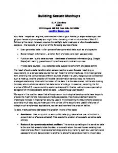
2.2.1.3. Distributed Denial of Service Attacks During the second half of 1999., several sites reported denial of service attacks involving distributed intruder tools. In typical distributed attack system, the "intruder" controls a small number of "masters", which in turn control a large number of
2-4
Chapter 2
Misuse of Information Systems
"daemons". These daemons can be used to launch packet flooding or other attacks against "victims" targeted by the intruder. This is shown on Figure 2.2.1. +----------+ +----------+ | attacker | | attacker | +----------+ +----------+ | | . . . --+------+---------------+------+----------------+-- . . . | | | | | | +----------+ +----------+ +----------+ | master | | master | | master | +----------+ +----------+ +----------+ | | | | | | . . . ---+------+-----+------------+---+--------+------------+-+-- . . . | | | | | | | | | | +--------+ +--------+ +--------+ +--------+ +--------+ | daemon | | daemon | | daemon | | daemon | | daemon | +--------+ +--------+ +--------+ +--------+ +--------+
Figure 2.2.1. Distributed denial of service attack The typical path of attack is attacker(s) --> master(s) --> daemon(s) --> victim(s). There are several tools for performing this type of attack, most often used are Trinoo, TFN (Tribe Flood Network) and Stacheldraht. These attacks combine intrusion on application level, which will be described later, with typical network level attack of flooding.
2.2.2. Vulnerabilities in Application Level Services The application level services can be used for different kind of attacks from gaining information about the system to more sophisticated attacks.
2.2.2.1. Gaining Information about the System Finger is one of services which is very appropriate to obtain the information about the users on the system. For example, fingering "@", "0", and "", as well as common names, such as root, bin, ftp, system, guest, demo, manager, etc., can reveal interesting information. What that information is depends on the version of finger that the "target" is running, but the most notable are account names, along with their home directories and the host that they last logged in from. Finger is one of the most dangerous services, because it is so useful for investigating a potential target. However, much of this information is useful only when used in conjunction with other data.
2-5
Chapter 2
Misuse of Information Systems
2.2.2.2. Getting Access After collecting information about the system, one can try to penetrate into it. There are many ways how to do that and only few examples will be done to show the principle. The tftp daemon does not require any password for authentication; if a host provides tftp without restricting the access (usually via some secure flag set in the inetd.conf file), an attacker can read and write files anywhere on the system. In the example, he gets the remote password file and place it in his local /tmp directory: evil % tftp tftp> connect victim.com tftp> get /etc/passwd /tmp/passwd.victim tftp> quit
Sendmail is a very complex program that has a long history of security problems. One can often determine the operating system, sometimes down to the version number, of the target, by looking at the version number returned by sendmail. This, in turn, can give hints as to how vulnerable it might be to any of the numerous bugs. In addition, one can see if they run the "decode" alias, which has its own set of problems: evil % telnet victim.com 25 connecting to host victim.com (128.128.128.1.), port 25 connection open 220 victim.com Sendmail Sendmail 5.55/victim ready at Fri, 6 Nov 93 18:00 PDT expn decode 250 quit
Running the "decode" alias is a security risk -- it allows potential attackers to overwrite any file that is writable by the owner of that alias - often daemon, but potentially any user. The following piece of mail will place "evil.com" in user zen's .rhosts file if it is writable: evil % echo "evil.com" | uuencode /home/zen/.rhosts | mail
[email protected]
A lot of information about the target can be found out by just asking sendmail if an address is acceptable (vrfy), or what an address expands to (expn). When the finger or rusers services are turned off, vrfy and expn can still be used to identify user accounts or targets. Vrfy and expn can also be used to find out if the user is piping mail through any program that might be exploited (e.g.vacation, mail sorters, etc.). It can be a good idea to disable the vrfy and expn commands.
2.2.2.3. Programmed Threats The next step after getting password file on any way is to use it to enter into the system. The problem attacker encounter then is how to hide his presence during the action he wants to perform in the system. For that reason programmed form of attacks
2-6
Chapter 2
Misuse of Information Systems
are used, as Trojan horses, logic or time bombs, viruses or worms. In fact all attempts to penetrate into the system can be done by programs too. The most serious threats are viruses and worms as they can spread between machines and programs in system, while other types of "malicious software" can be limited on one machine only. Programmed types of threats will be discussed in more detail in next chapter.
2-7
Chapter 2
Misuse of Information Systems
2-8
Chapter 3
Programed Threats
3. PROGRAMMED THREATS Programmed threats to information security are numerous. Some of the most frequent attacks will be described in following text. There are two types of such threats: -
non-reproducing threats that do not have built-in ability to replicate themselves self-reproducing threats that do have built-in ability to replicate themselves
Many of attacks, which will be described, are technically complex and will not all be explained in detail.
3.1. Non-reproducing Threats Most common types of non-reproducing threats will be described bellow One classic software attack is the trap door or back door. A trap door is a quick way into a program; it allows program developers to bypass all of the security built into the program, now or in the future. Typical trap doors use such system features as debugging tools, program exits that transfer control to privileged areas of memory, undocumented application calls and parameters, and many others. Session hijacking is a relatively new type of attack in the communications. Some systems do not disconnect immediately when a session is terminated. Instead they allow a user to re-access the interrupted program for a short period. An attacker with a good knowledge of communications operations can take advantage of this fact to reconnect to the terminated session. Tunneling use one data transfer method to carry data for another method. Tunneling is an often legitimate way to transfer data over incompatible networks, but is illegitimate when it is used to carry unauthorized data in legitimate data packets. Timing attacks are another way to get unauthorized access to software or data. These include the abuse of race conditions and asynchronous attacks. In race conditions, there is a race between two processes operating on a system; the outcome depends on who wins the race. On certain type of Unix systems the attackers could exploit a problem with files known as setuid shell files to gain superuser privileges. Asynchronous attacks are another way of taking advantage of dynamic system activity to get access. Computing systems are often called upon to do many things in the same time. In these cases, the operating system simply places user requests into a queue, then satisfy them according to predetermined set of criteria. Asynchronous means that computer does not simply satisfy requests in the order in which they were performed, but according to some other scheme. A skilled programmer can figure out how to penetrate the queue and modify the data that is waiting to be processed or printed. 3-1
Chapter 3
Programed Threats
Buffer overflow attacks happen when attacker tries to put more data into a buffer than it can handle. A buffer is an abstraction, an area of memory in which some type of text or data will be stored. Programmers make use of such a buffer to provide preassigned space for a particular block or blocks of data. When buffer overflow occurs, overload characters are put somewhere in memory, at another address (an address the programmer did not intend for those characters to go). Attackers, by manipulating where those extra characters end up, can cause arbitrary commands to be executed by the operating system. Most often, this technique is used by local users to gain access to a root shell. Unfortunately, many common utilities have been found to be susceptible to buffer overflow attacks. Trojan horses are attacks on the integrity of information that is stored in the system. A Trojan horse is the method for inserting instructions in a program so that program performs an unauthorized function while apparently performing a useful one. The typical situation is: Trojan horse is hidden in an application program that is user eager to try, e.g. new game or a program that promises to increase efficiency. Inside the horse are the instructions that will cause the entire system to crash when the program is run. Logic bomb is a harmful program that is triggered by a certain event or situation. Logic bomb’s code may be a part of a regular program or set of programs, and not activated when first run. The trigger may be any event that can be detected by software, such as date, username, presence or the absence of a certain file, etc. Programmed denial of service attacks can crash or slow down systems when they are run. The programs of this type may even cause the crashing of the individual systems on the network remotely. The examples of such attacks are before mentioned distributed denial of service attacks.
3.2. Self – reproducing Threats The most known representative of self – reproducing threats is computer virus. In general, computer virus is a sequence of symbols. A sequence of symbols v is an element of viral set V if, when interpreted, it causes some other element v’ of that viral set to appear somewhere else in the system at the later point of time [2]. (Fig. 3.2.1.)
v'
v
v'
v
V
V
Figure 3.2.1. Formal Definition of Computer Virus 3-2
Chapter 3
Programed Threats
The above definition of computer virus is not used very often. The most common definition is [2] : a virus is a program that can infect other programs by modifying them to include, a possibly evolved, version of itself. The infection process is the most distinguishable property of the computer virus (Fig 3.2.2.) Computer viruses may do some damage in computing system where they are located, i.e. they may contain Trojan horse or a logic bomb, but they do not necessarily have to. However, any virus has to have ability to spread itself through the system, otherwise it is not considered as a virus.
VIRUS
PROGRAM 1
INFECTED PROGRAM 1
PROGRAM 2
INFECTED PROGRAM 2
Figure 2.2.2. Infection by computer virus
3.2.2. The Types of Viruses The viruses are able to replicate, that is to create (possibly modified) copies of themselves, but the virus has to attach itself to a host (carrier of virus), in the sense that execution of the host implies execution of the virus. The viruses can be classified by their hosts. There are four main types of viruses and several variations [30]. Boot sector viruses alter the program that is in the first sector (boot sector) of every DOS-formatted disk. Generally, a boot sector infector executes its own code, which usually infects the boot sector or partition sector of the hard disk, then continues the PC start – up process. File viruses attach themselves to a file, usually an executable application. A file virus infects other files when the program to which is attached is run. 3-3
Chapter 3
Programed Threats
Multipartite viruses infect boot sectors and files. Typically, when an infected file is executed, it infects the hard disk boot sector or partition sector, and thus infects subsequent floppy disks used or formatted on the target system. Macro viruses infect data files, which contain embedded executable code such as macros. They typically infect global settings files such as Word templates so that subsequently edited documents are contaminated with the infective macros. There are several variations of viruses, regarding how they can hide their presence: Stealth viruses have ability to conceal their presence from anti-virus programs. Polymorphic viruses are viruses that cannot be detected by searching for a simple, single sequence of bytes in a possibly infected file, since they change with every replication. Companion viruses are viruses that spread via a file, which runs instead of file the user intended to run, and then runs the original file. There is also a special species of the virus, which is called worm. The worm spreads through the networked systems.
3.2.3. Examples of Viruses and Worms Most prevailing viruses in today's computer world are macro viruses and so called email worms. Some of them (e.g. Melissa) may combine both characteristics. The best way to learn behavior of such "creatures" is to describe some of them in more detail.
3.2.3.1. Concept WM/Concept was one of first macro viruses reported "in the wild" and used to be extremely widespread during 1995-1997. Nowadays it is almost (but not completely) extinct. WordMacro/Concept - also known as Word Prank Macro or WW6Macro - is a macro virus, which has been written with the Microsoft Word v6.x macro language. It has been reported in several countries, and seems to had no trouble propagating in the wild. WordMacro/Concept consists of several Word macros. Since Word macros are carried with Word documents themselves, the virus is able to spread through document files. The situation is made worse by the fact that WordMacro/Concept is also able to function with Microsoft Word for Windows 6.x and 7.x, Word for Macintosh 6.x, as well as in Windows 95 and Windows NT environments. It is, truly, the first functional multi-environment virus, although it can be argued that the effective operating system of this virus is Microsoft Word, not Windows or MacOS.
3-4
Chapter 3
Programed Threats
The virus gets executed every time an infected document is opened. It tries to infect Word's global document template, NORMAL.DOT (which is also capable of holding macros). If it finds either the macro "PayLoad" or "FileSaveAs" already on the template, it assumes that the template is already infected and ceases its functioning. If the virus does not find "PayLoad" or "FileSaveAs" in NORMAL.DOT, it starts to copy the viral macros to the template and displays a small dialog box on the screen. The box contains the number "1" and an "OK" button, and its title bar identifies it as a Word dialog box. This effect seems to have been meant to act as a generation counter, but it does not work as intended. This dialog is only shown during the initial infection of NORMAL.DOT. After the virus has managed to infect the global template, it infects all documents that are created with the "Save As" command. It is then able to spread to other systems on these documents - when a user opens an infected document on a clean system, the virus will infect the global document template. The virus consists of the following macros: AAAZAO AAAZFS AutoOpen FileSaveAs PayLoad
"AutoOpen" and "FileSaveAs" are legitimate macro names, and some users may already have attached these macros to their documents and templates. In this context, "PayLoad" sounds very ominous. It contains the text: Sub MAIN REM That's enough to prove my point End Sub
However, the "PayLoad" macro is not executed at any time.
3.2.3.2. Melissa A virulent and widespread computer virus was found on Friday, March 26, 1999. This virus has spread all over the globe within just hours of the initial discovery, apparently spreading faster than any other virus before. The virus, known as W97M/Melissa, spreads by e-mailing itself automatically from one user to another. When the virus activates it modifies user's documents by inserting comments from the TV series "The Simpsons". Even worse, it can send out confidential information from the computer without users' notice. The virus was discovered on Friday, late evening in Europe, early morning in the US. For this reason, the virus spread in the USA during Friday. Many multinational companies reported widespread infections, including Microsoft and Intel. Microsoft closed down their whole e-mail system to prevent any further spreading of the virus. W97M/Melissa was initially distributed in an internet discussion group called alt.sex. The virus was sent in a file called LIST.DOC, which contained passwords for X-rated
3-5
Chapter 3
Programed Threats
websites. When users downloaded the file and opened it in Microsoft Word, a macro inside the document executed and e-mailed the LIST.DOC file to 50 people listed in the user's e-mail alias file ("address book"). The e-mail looked like this: From: (name of infected user) Subject: Important Message From (name of infected user) To: (50 names from alias list) Here is that document you asked for ... don't show anyone else ;-) Attachment: LIST.DOC
Melissa can arrive in any document, not necessarily just in this LIST.DOC where it was spread initially. Most of the recipients are likely to open a document attachment like this, as it usually comes from someone they know. After sending itself out, the virus continues to infect other Word documents. Eventually, these files can end up being mailed to other users as well. This can be potentially disastrous, as a user might inadvertently send out confidential data to outsiders. The virus activates if it is executed when the minutes of the hour match the day of the month; for example, 18:27 on the 27th day of a month. At this time the virus will insert the following phrase into the current open document in Word: "Twenty-two points, plus triple-word-score, plus fifty points for using all my letters. Game's over. I'm outta here". This text, as well as the alias name of the author of the virus, "Kwyjibo", are all references to the popular cartoon TV series called "The Simpsons". W97M/Melissa works with Microsoft Word 97, Microsoft Word 2000 and Microsoft Outlook 97 or 98 e-mail client. One does not need to have Microsoft Outlook to receive the virus in e-mail, but it will not spread itself further without it. Melissa will not work under Word 95. Melissa will not spread further under Outlook Express. Melissa can infect Windows 95, 98, NT and Macintosh users. If the infected machine does not have Outlook or internet access at all, the virus will continue to spread locally within the user's own documents.
3.2.3.3. Love Letter Worm The "Love Letter" worm is a malicious VBScript program, which spreads in a variety of ways. As of 5:00 pm EDT(GMT-4) May 8, 2000, the CERT Coordination Center has received reports from more than 650 individual sites indicating more than 500,000 individual systems are affected. In addition, there were several reports of sites suffering considerable network degradation as a result of mail, file, and web traffic generated by the "Love Letter" worm. One can be infected with the "Love Letter" worm in a variety of ways, including electronic mail, Windows file sharing, IRC, USENET news, and possibly via webpages.
3-6
Chapter 3
Programed Threats
3.2.3.3.1. Electronic Mail When the worm executes, it attempts to send copies of itself using Microsoft Outlook to all the entries in all the address books. The mail it sends has the following characteristics: - An attachment named "LOVE-LETTER-FOR-YOU.TXT.VBS" - A subject of "ILOVEYOU" - The body of the message reads "kindly check the attached LOVELETTER coming from me." People who receive copies of the worm via electronic mail will most likely recognize the sender. 3.2.3.3.2. Internet Relay Chat When the worm executes, it will attempt to create a file named script.ini in any directory that contains certain files associated with the popular IRC client mIRC. The script file will attempt to send a copy of the worm via DCC to other people in any IRC channel joined by the victim. 3.2.3.3.3. Executing Files on Shared File Systems When the worm executes, it will search for certain types of files and replace them with a copy of the worm. Executing (double clicking) files modified by other infected users will result in executing the worm. Files modified by the worm may also be started automatically, for example from a startup script. 3.2.3.3.4. Reading USENET News There have been reports of the worm appearing in USENET newsgroups. 3.2.3.3.5. Impact When the worm is executed, it takes the following steps: 1. Replaces Files with Copies of the Worm When the worm executes, it will search for certain types of files and make changes to those files depending on the type of file. For files on fixed or network drives, it will take the following steps: - For files whose extension is vbs or vbe it will replace those files with a copy of itself. - For files whose extensions are js, jse, css, wsh, sct, or hta, it will replace those files with a copy of itself and change the extension to vbs. For example, a file named x.css will be replaced with a file named x.vbs containing a copy of the worm. - For files whose extension is jpg or jpeg, it will replace those files with a copy of the worm and add a vbs extension. For example, a file named x.jpg will be replaced by a file called x.jpg.vbs containing a copy of the worm. - For files whose extension is mp3 or mp2, it will create a copy of itself in a file named with a vbs extension in the same manner as for a jpg file. The original file is preserved, but its attributes are changed to hidden. Since the modified files are overwritten by the worm code rather than being deleted, file recovery is difficult and may be impossible.
3-7
Chapter 3
Programed Threats
Users executing files that have been modified in this step will cause the worm to begin executing again. If these files are on a file system shared over a local area network, new users may be affected. 2. Creates an mIRC Script While the worm is examining files as described in the previous section, it may take additional steps to create a mIRC script file. If the file name being examined is mirc32.exe, mlink32.exe, mirc.ini, script.ini, or mirc.hlp, the worm will create a file named script.ini in the same folder. The script.ini file will contain: [script] n0=on 1:JOIN:#:{ n1= /if ( $nick == $me ) { halt } n2= /.dcc send $nick DIRSYSTEM\LOVE-LETTER-FOR-YOU.HTM n3=}
where DIRSYSTEM varies based on the platform where the worm is executed. If the file script.ini already exists, no changes occur. This code defines an mIRC script so that when a new user joins an IRC channel the infected user has previously joined, a copy of the worm will be sent to the new user via DCC. The script.ini file is created only once per folder processed by the worm. 3. Modifies the Internet Explorer Start Page If the file \WinFAT32.exe does not exist, the worm sets the Internet Explorer Start page to one of four randomly selected URLs. These URLs all refer to a file named WIN-BUGSFIX.exe, which presumably contains malicious code. The worm checks for this file in the Internet Explorer downloads directory, and if found, the file is added to the list of programs to run at reboot. The Internet Explorer Start page is then reset to "about:blank". 4. Sends Copies of Itself via Email The worm attempts to use Microsoft Outlook to send copies of itself to all entries in all address books. 5.Modifies Other Registry Keys In addition to other changes, the worm updates the following registry keys: HKLM\Software\Microsoft\Windows\CurrentVersion\Run\MSKernel32 HKLM\Software\Microsoft\Windows\CurrentVersion\RunServices\Win32DLL HKLM\Software\Microsoft\Windows\CurrentVersion\Run\WIN-BUGSFIX HKCU\Software\Microsoft\Windows Scripting Host\Settings\Timeout HKCU\Software\Microsoft\Internet Explorer\Main\Start Page HKCU\Software\Microsoft\WAB\*
When the worm is sending email, it updates the last entry each time it sends a message. If a large number of messages are sent, the size of the registry may grow significantly, possibly introducing additional problems.
3-8
Chapter 4
Protection of Information Systems
4. PROTECTION OF INFORMATION SYSTEMS Several types of threats to information systems were considered in previous chapters. In this chapter the methods of protection will be described. Today’s protection of information systems can be roughly divided in two important areas: prevention and active protection. Prevention includes all measures to be taken before a security incident happens. Active protection includes tools and methods for real – time protection.
4.1. Prevention Prevention is the most important part of overall information protection framework. It includes some non – technical methods such as establishing security policy, security standards, defining security procedures, education and training, regular checking of employees and equipment, raising the level of knowledge of existing laws concerning computer crime. The most highly publicized computer security breaches are hacker attacks, but security experts say the biggest dangers, both accidental and deliberate, to information technology resources are within the organization. Threats range from employees choosing easily guessable passwords, not backing up data, or leaving connected computers unattended, etc. That is why raising the level of awareness of security risks within the organization is extremely important. Therefore is the understanding of security risks the first step in developing a security policy and securing organization’s network. The key to providing consistent, cost effective, efficient, and appropriate levels of security in an organization is to ensure that the direction of security has been carefully considered, documented and communicated. The security policy and its supporting standards provide this direction, in terms of the security requirements of the organization. Without it security would be implemented on an ad hoc basis leading to costly inconsistencies and, very likely, flaws in the protection offered. The prevention methods are described in more detail in Appendix B.
4.2. Active Protection Although prevention is the most important aspect of security, attention should also be paid to other means of protection. So, for a safer and more secure information system we use all means of protection. After prevention, the next step is active protection. Active protection means to apply in real conditions all the measures defined by security policy, standards and procedures. In general, active protection consists of network and Internet security, system and applications protection, incident response and implementing laws concerning computer crime.
4-1
Chapter 4
Protection of Information Systems
4.2.1. Network and Internet Security Network and Internet security includes protection of communication devices such as modems, controlling access to servers, network monitoring, network scanning, securing network services, securing network configuration, filtering network traffic (routers, firewalls).
4.2.1.1. Secure Modems Securing modems is one of the important steps in securing information inside an organization and elsewhere. Modems raise a number of security concerns because they are a link between the computer and the outside world. They are a popular and widely used tool for breaking into networks because they are often unguarded. The first step to protect modems is their physical protection, i.e. placing them in a physically secure location. They should be protected from rewiring or altering. Further, their telephone numbers should be protected and monitored. The modem access should be authorized allowing that way easier tracing of an intruder.
4.2.1.2. Scanners As it was already mentioned earlier, networks are prone to security threats because of their ability to let users exchange and modify information. That is why it is important that networks be regularly checked and monitored for any signs of unusual activity. There are numerous tools, which allow network scanning for known vulnerabilities. Scanner is a program that automatically detects security weaknesses in a remote or local host. Most of the scanners are TCP ports scanners, which are programs that attack TCP/IP ports and services, such as telnet or ftp, and record the response from the target. Although they are commonly written for execution on Unix workstations, scanners are now written for use on almost any operating system. The primary attributes of a scanner are: a) the capability to find a machine or network, b) the capability, once having found a machine, to find out what services are being run on the host, c) the capability to test those services for known security vulnerabilities. There are many scanners available on the Internet. Some of the most popular are: ISS (Internet Security Scanner), Strobe, SATAN (Security Administrator’s Tool for Analyzing Networks), Jakal, etc.
4.2.1.3. Firewalls In terms of security, the best way to protect information in an organization is physical isolation. Some companies and organizations still feel that it is best not to connect to outside networks since the risk of security breaches is too high. However, today it is hard to resist the opportunities the Internet provides. E-mail, news, WWW and other services are a useful tool in any business. That is why some organizations use firewalls to protect their security, thus retaining some amount of isolation but still be connected to the outside information world. 4-2
Chapter 4
Protection of Information Systems
One of the main ideas behind a firewall is that the network will remain theoretically invisible (or at least unreachable) to anyone not authorized to connect. This process works through the exclusionary schemes that one can apply using a firewall. There are different kinds of firewalls, and each type has its advantages and disadvantages. The most common type is referred to as a network – level firewall. Network – level firewalls are usually router based. The rules of who and what can access the network is applied at the router level. This scheme is applied through a technique called packet filtering, which is the process of examining the packets that come to the router from the outside world. The source address of each incoming connection (that is, the address from which the packets originated) is examined. After each IP source address has been identified, whatever rules were instituted will be enforced. For example, the router can reject any packets forwarded from evil.com. These packets never reach the internal server or the network beneath it. Router – based firewalls are fast because they only perform cursory checks on the source address and therefore there is no real demand on the router. There are many free and commercial packet-filtering tools on the Internet such as TCP_Wrappers, NetGate, Internet Packet Filter, etc. There are also other types of firewalls. A common type is application – proxy firewall (sometimes referred to as application gateway). Application gateways are software based. When the remote user contacts a network running an application gateway, the gateway blocks the remote connection. Instead of passing the connection along, the gateway examines various fields in the request. If these meet a set of predefined rules, the gateway creates the bridge between the remote host and the internal host. For example, in a typical application gateway scheme, IP packets are not forwarded to the internal network. Instead, a type of translation occurs, with the gateway as the conduit and interpreter. This gateway scheme has a cost in terms of speed. Because each connection and all traffic are accepted, negotiated, translated and reforwarded, this implementation can be slower than router – based packet filtering. A typical example of an application – firewall package is the TIS (Trusted Information Systems) FWTK (Firewall Tool Kit). Although firewalls are a very useful tool in protecting the security of information since they control the amount and kinds of traffic between the external and internal network of the organization they should always be used in addition to other measures to maintain a high level of security. Packet filters, when used in conjunction with powerful auditing tools, can greatly assist in protecting the network and identifying intruders.
4.2.1.4. Sniffers A sniffer is any device, whether software or hardware, that collects information traveling along a network. That network could be running any protocol: Ethernet, TCP/IP, IPX, or others (or any combination of these). Attackers to information system more often use sniffers to collect passwords, but if they are used properly they may be used for the network traffic control.
4-3
Chapter 4
Protection of Information Systems
The purpose of the sniffer is to place the network interface, e.g. Ethernet adapter, into promiscuous mode and by doing so, to capture all network traffic. Promiscuous mode refers to that mode where all workstations on a network listen to all traffic, not simply their own. In other words, non-promiscuous mode is where a workstation only listens to traffic route in its own address. In promiscuous mode, the workstation listens to all traffic, no matter what address this traffic was intended for. Sniffers capture network traffic. This network traffic, irrespective of what protocol is running, is composed of packets. These are exchanged between machines at a very low level of the operating system network interface. However, they also may carry vital data, sometimes very sensitive data. Sniffers are designed to capture and archive that data for later inspection.
4.2.2. Individual System Protection System protection includes user authentication, regular checking of security holes in the system, monitoring activities in the system, monitoring accounts and recovery procedures.
4.2.2.1. Auditing and Logging Tools Before any other security measures become meaningful, there must be a way to reliably identify authorized computer system users and lock others out. Once identified, authorized users should have limited access to the system's resources, consistent with their work responsibilities. The most commonly used authentication technique is a password. But many passwords can be easily guessed, which is why more sophisticated authentication techniques are needed. Every administrator should know weak spots in his system and monitor them closely. Auditing and logging tools are suitable for system monitoring, access control, checking security holes in the system. There are many various types of such tools, most of them available on Internet, such as COPS, Argus, NetLog, etc.
4.2.2.2. Intruder detection Intruder detection system observes user behavior on a monitored computer system and learns what is normal for individual users, groups of users and the overall system behavior. Observed behavior is marked as a potential intrusion if it deviates significantly from the expected behavior. An intruder is likely to exhibit a behavior pattern that is significantly different from that of a legitimate user and can be detected through observation of this statistically unusual behavior. This idea is the basis for enhancing system security by monitoring system activity and detecting atypical behavior. Such a monitoring system is capable of detecting intrusions that could not be detected by any other means, e.g. intrusions that exploit unknown vulnerabilities. In addition, there can be included detection of intrusions that exploit known vulnerabilities through the use of explicit expert-system
4-4
Chapter 4
Protection of Information Systems
rules. An example of such a tool is IDES (Intrusion-Detection Expert System), being developed at SRI International’s Computer Science Laboratory. It is a comprehensive system that uses statistical algorithms for anomaly detection, as well as an expert system that encodes known intrusion scenarios.
4.2.3. Applications protection Applications protection means use of legal software, anti-virus protection, and regular installing of patches and fixes to remove existing security holes.
4.2.3.1. Anti-virus protection There are many tools available for protection against computer viruses. They can roughly be divided in three types: activity monitors, integrity checking or changedetection tools and scanners. 4.2.3.1.1. Activity monitors An activity monitor watches for suspicious activities in computer system. It may, for example, check for any calls to format a disk or attempts to alter or delete a program file while a program other than the operating system is in control. It may further check for any program that performs “direct” activities with hardware, without using the standard system calls. The drawback of activity monitors is great amount of false alarms. It is very hard to tell the difference between a word processor updating a file and a virus infecting a file. An activity monitor may continually ask for confirmation of valid activities, so the user can decide to switch it off. Restricting the operations that a computer can perform, some of computer viruses can be eliminated. Unfortunately, that way the most of the usefulness of the computer is eliminated too. There are several activity monitors available, such as Flu Shot or NVC.SYS 4.2.3.1.2. Integrity checkers Integrity checkers or change detectors are programs that examine system and/or program files and configuration, store the information, and compare it against the actual configuration at a later time. Most of these programs perform a checksum or cyclic redundancy checks (CRC) that will detect changes to a file even if the length is unchanged. Some programs will use sophisticated encryption techniques to generate a signature, which may in some extent prevent the virus attack. A sufficiently advanced integrity checker, which takes all factors including system areas of the disk and the computer memory into account, has the best chance of detecting all current and future viral strains. There are numerous implementations of
4-5
Chapter 4
Protection of Information Systems
integrity checking software. Some versions run only at boot time; others check each program as it is run. They may attach a small piece of code to the programs they are protecting, although this may cause programs that have their own change-detection features, or nonstandard internal structures, to fail. Some programs only protect system software; others only protect program files. Integrity checkers may keep the signature file in the root directory or in the “local” directories. However, change detection also has the highest possibility of false alarms, since it will not know if change is viral or valid. The addition of intelligent analysis of the changes detected may assist with this failing. The most known example of an integrity checker is Integrity Master.
4.2.3.1.3. Scanners Scanners are programs that looks for known viruses by checking for recognizable patterns (“scan strings”, “search strings”, “signatures”). They examine files, boot sectors and memory for evidence of viral infection. These programs generally look for sections of program code that are known to be in specific viral programs, but not in most other programs. There are several variations of such programs. TSR scanner is a memory resident program that checks for viruses while other programs are running. It may have some of the characteristics of an activity monitor. VxD scanner is a scanner that works under MS Windows platform, which checks for viruses continuously. Heuristic scanner is a scanner that inspects executable files for code using operations that might denote an unknown virus. The scanners can only find infections after they occur, but that does not mean that scanners cannot play a preventive role in protecting the system. If scanner is used consistently to check each disk or file that enters a system, and is kept up to date, the chance of a viral infection being allowed to enter is greatly reduced. The most known examples of scanners are F-Prot and AVP.
4.3. Automated Adaptive Protection Systems The protective tools can be roughly divided into two types: non - adaptive ones and adaptive automated protective tools. Non – adaptive tools were described earlier and are still prevailing today while fully adaptive automated protection tool exists mostly as a concept. Nevertheless, it is worthwhile to present this concept which will certainly get more attention in the near future.
4-6
Chapter 4
Protection of Information Systems
Automatization of the protection systems and using adaptiveness allows easy handling (user friendliness) and can reduce error level. Adaptiveness is the ability of a system to adapt to changes that could significantly influence the existence of the system. Adaptive systems receive information about their environment and about the desired behavior of the system. On the basis of that information the system can change the performance of system till (ideally) the real behavior of system corresponds to the desired one.
4.3.1. Concept of Adaptive System Adaptive system works in environment which manifestations z are represented by the set Z. The system must receive some information about the desired behavior from set M. The system’s real behavior is determined by some decision rule (algorithm), i.e. y = d(z,q) where q is variable part of system which can be changed during adaptation. The aim of an adaptive system is to set adequate behavior y, i.e. to adjoin corresponding y to each pair [z,m] to obtain the minimum loss by criterion Q(z,m,q) which evaluate the difference between the desired (m) and the real behavior (y) and represents the price which has to be paid for the adaptation. z m
Q(z,m,q)
y=d(z,q)
y
q
Figure 4.3.1. Adaptive system
Adaptive system is system with two inputs and one output which is: 1.) described by: AS = [ Z, M, Y, D, Q ] where: Z is a set of environment manifestations; z is element of Z M is a set of information about desired behavior; m is element of M Y is a set of outputs; y is element of Y D is a set of decision rules, y = d(z,q) Q is a criterion for minimum loss Q(z,m,q) 2.) and for each pair [z,m,] is searching for parameter q' for which the following holds: Q(z,m,q') = min Q(z,m,q) q 4-7
Chapter 4
Protection of Information Systems
In an adaptive systems the new parameter of adaptation q is set every time the criterion Q does not reach a minimum. Adaptation process can consist of few iterations, taken regardless on previous value of q. In that case adaptive systems does not “memorize” information about previous behavior. If an adaptive system has the ability to memorize previous behavior and to set the parameter q on the basis of such “experience” it means that adaptive system has ability to “learn”. The approximate model of an adaptive protection system is shown in Fig.4.3.2.
uc
_ +
u
R
v
q
M ym
y
S
O.E.
yo
A
Figure 4.3.2. Adaptive Protection System Where: S is the information system, which is to be protected O.E. is observing element M is the model of desired behavior (security model) A is adaptive mechanism R is regulator uc is the control signal u is the input signal to computer system v is the signal of disturbance to system, e.g. computer virus or intrusion attempt y is the output signal from computer system, which represents the real state of computer system yo is the output signal from observing element ym is the information from the model of desired behavior q is the output signal from the adaptive mechanism, it is variable parameter of the regulator The term “signal” refers here to any interpretable sequence of symbols (data, instruction, etc.).
4-8
Chapter 4
Protection of Information Systems
4.3.2. Model of Desired Behavior (Security Model) The model of desired behavior gives information about standard allowed features in the information system. It may be based on one of existing security models. Those models can be combined or an arbitrary new security model can be used. The records in security model’s database may have the form: [SYSTEM FUNCTION; SUBJECT; OBJECT; PARAMETER] Subjects are users, processes, etc. Objects are files, programs, etc. The set of possible system functions includes: get access, give access, create object, delete object, change object security level, change subject security level, etc. Parameters indicate the kind of access allowed.
4.3.3. Observing Elements Observing elements check performance and vital parts of the computer system. The results may be stored in audit database which records have the same form as those in security model’s database. Parameters in audit database records indicate the kind of access requested.
4.3.4. Adaptive Mechanism The main task of the adaptive mechanism is to alter the performance of the regulator when an “abnormal” state of the computer system is detected. More detailed scheme of adaptive mechanism is shown on Figure 4.3.3. q
A A.E. u
h Q.E. f ym
K.D.
e g
yo
R.E.
Figure 4.3.3. Adaptive Mechanism 4-9
Chapter 4
Protection of Information Systems
Where: R.E. is recognition element K.D. is knowledge database Q.E. is criterion element A.E. is adaptive element e is output signal from recognition element, i.e. signal of difference f is signal from criterion element to recognition element g is information from/to knowledge database h is output signal from criterion element ym, yo, u, q are signals as noted earlier in the text Recognition element compares the signals from security model and observing element. Additionally it can compare the signal yo with information stored in knowledge database(s). Knowledge database contains records about known irregular states. There can be more than one such database. On the basis of performed comparisons, recognition element gives the signal of difference e to the criterion element. Criterion element checks if the received signal is in the limits of the certain criterion of adaptation. It passes the signal h to adaptive element which sets corresponding parameter q for the regulator.
4.3.5. Regulator The regulator keeps information system in standard (“regular”) state of performance according to information given from the adaptive mechanism. It activates observing elements. Furthermore, regulator performs the routines for reconstruction of “normal” state of the computer system.
4.3.6. Principal work The performance of information system S can be approximated by linear mathematical process: A(p)y(k) = B(p)u(k) + C(p)v(k)
(4.3.6.1)
Where: k is index of time y(k) is output signal u(k) is input signal v(k) is disturbance signal (e.g. computer virus or an intrusion) p is operator of precedence/delay A(p), B(p), C(p) are polynoms in p of na, nb, nc order The equation (4.3.6.1) may be rewritten as: y(k) = B*(p)u(k) + C*(p)v(k)
(4.3.6.2)
4-10
Chapter 4
Protection of Information Systems
where: B*(p) = B(p)/A(p) C*(p) = C(p)/A(p) The observing model O.E. measures y(k) and gives its output yo(k). In ideal case (measurement errors neglected) holds: yo(k) = y(k) = B*(p)u(k) + C*(p)v(k)
(4.3.6.3)
The model of desired behavior M gives an output signal ym when receiving control signal uc (M maps uc to ym): M : uc → ym
(4.3.6.4)
Signal ym has a form: ym (k) = M(p)u(k)
(4.3.6.5)
where M(p) is a polynom in p of nm order. Recognition element R.E. compares first yo(k) and ym(k) and gives the signal of difference e(k): e(k) = ym(k) - yo(k) = M(p)u(k) - B*(p)u(k) - C*(p)v(k) = = [M(p) - B*(p)]u(k) - C*(p)v(k)
(4.3.6.6)
Signal e(k) is sent to criterion element Q.E. that checks if received signal is in the limits of certain criterion of adaptation. The condition for criterion function Q[e(k)] to have an extreme is:
∇ Q[e(k)] = grad Q[e(k)] = 0
(4.3.6.7)
It is required that criterion function Q[e(k)] has only one extreme, i.e. minimum. If minimum is not found in the first try, criterion element Q.E. sends signal f to recognition element R.E that performs then further comparison. It compares yo(k) with g(k), an information from knowledge database K.D. : g(k) = K(p)w(k) = K1(p)u(k) + K2(p)v(k)
(4.3.6.8)
e'(k) = g(k) - yo(k) = K(p)w(k) - B*(p)u(k) - C*(p)v(k) = = K1(p)u(k) + K2(p)v(k) - B*(p)u(k) - C*(p)v(k) = = [K1(p) - B*(p)]u(k) - [K2(p) - C*(p)]v(k)
(4.3.6.9)
This new signal of difference e’(k) is sent again to criterion element and the minimum is searched for Q[e’(k)]. It is possible to have more than one knowledge database, so 4-11
Chapter 4
Protection of Information Systems
the above procedure can be repeated several times. When the final result of searching minimum procedure is obtained, criterion element sends a signal h to adaptive element, which accordingly sets the parameter q for the regulator R. From (4.3.6.6) and (4.3.6.7) follows that minimum is obtained in the first try when: [M(p) - B*(p)] = 0 => M(p) = B*(p) ; C*(p) = 0
(4.3.6.10)
This means that the ideal “normal” state of the computer system is obtained when real state corresponds to the desired one: y(k) = ym(k) = M(p)u(k)
(4.3.6.11)
Parameter q has to be set in the way that the regulator keeps state (4.3.6.11) under any circumstances. According to the value of parameter q the regulator performs corresponding routines to maintain the regular (“normal”) performance of the computer system. When an irregular (“abnormal”) state was detected, i.e. the minimum of adaptation criterion is not found in the first try, from (4.3.6.8) and (4.3.6.9) follows that minimum is obtained in the next try when: [K1(p) - B*(p)] = 0 => K1(p) = B*(p) [K2(p) - C*(p)] = 0 => K2(p) = C*(p)
(4.3.6.12)
This means that “patterns” of irregular computer system performance are known and regulator is instructed by parameter q to perform routines for “reconstruction” of “normal” state, e.g. removal of computer virus if known virus is detected. If no minimum of adaptation criterion is found after several comparisons, then regulator R is instructed to initiate additional measurement until a satisfying state of the system is obtained. The irregular state, which caused such an action, can be recorded in knowledge database for the future use. This way the adaptive mechanism has ability to “learn”.
4-12
Chapter 5
Vulnerabilities in Present Protection Systems
5. VULNERABILITIES IN PRESENT PROTECTION SYSTEMS Various protection tools were mentioned in previous chapter. There are already many such systems available on the market or are still under research. Nevertheless, there is no perfect protection tool, which may assure absolute security of information systems. There are various reasons for that and some of them will be mentioned in this Chapter.
5.1. Human Factors The fact, which is often forgotten when talking about protection systems, is that people make them to be used by other people. The users implementing particular protection tool do not have to be skilled enough to use it optimally. Furthermore, they do not have to be skilled enough to understand the output signals from the protection tools, so they may act in an inappropriate way which may consequently produce more damage than malicious act (an intrusion or infection by computer virus) itself. Such problems are called controllability problems. There is another group of problems, which disturbs more people who produce or develop protection tools. It is the problem of definitions. It is hard to discern “normal” from “abnormal” behavior in the information systems and therefore to produce exact models or patterns of “abnormal” behavior which could be automatically included in protection tools.
5.1.1. Controllability Problems When user chooses a protection tool for his or her information system, it is useful to see how much is system controllable regarding possible malicious activity in the system (an intrusion, infection by computer virus, etc.).
5.1.1.1. Open-loop Control System In general the following situation is possible:
u
S
y
Figure 5.1.1. Open-loop Control System
5-1
Chapter 5
Vulnerabilities in Present Protection Systems
u is input variable, in this case any process, program or executable routine, S is information system, and y is output variable, which could have two possible outcomes: a) desired, i.e. process or program is unchanged and performs its task, b) undesired, i.e. process or program is changed without user’s authorization and it may or may not be able to perform its task.
5.1.1.2. Closed-loop Control System When a protection tool is entered into system a form of closed-loop control system is obtained: v
_
u
y
S
+ x
R
e
_
w
+
Figure 5.1.2. Closed-loop Control System where u and y are as before, S is information system, R is regulator, which in this case contains both a protection tool and a user, w is regulating variable, x is an output variable from the regulator and v is error or noise.
5.1.1.3. An Example Suppose that the chosen protection tool is a non-TSR (resident in memory) anti-virus scanner. The user notices that something has happened to an executable program in the system. The user suspects virus activity and decides to reboot the system and run a scanner from a write protected diskette (w). When the anti-viral program is run (R) the output x is obtained, i.e. a message from the scanner. Error (v) added to this signal can be a false positive (e.g. the scanner recognized as a virus something that is not a virus) or false negative (e.g. the scanner missed a virus). If no error occurs and virus is detected or virus is not detected, the user will make correct changes to the system (e.g. remove the infected program or correct bug in the system that made the user think that a virus was present). If the error is greater than the signal from the scanner the user will make an incorrect change to the system (e.g. remove an uninfected program marked as infected in the case of a false positive or leave an infected program in the system in the case of false negative). Similar reasoning applies to other types of anti–viral tools. Other protection tools may also be prone to false negative or false positive alarms. If the user has not enough experience to discern false alarm from the real one, errors are possible to happen.
5-2
Chapter 5
Vulnerabilities in Present Protection Systems
5.1.1.4 Control Problems It is important to stress the significant role of the user in the regulation process and the noticeable importance of error, which can have significant effect on the desired output from the system. This means if the error level is high (i.e. a significant amount of false positives or false negatives exists) and/or the user is not skilled enough to deal with all the problems caused by a possible virus infection or intrusion, control of system will be poor with high probability that a virus or intruder will do some damage to the system.
5.1.2. Problems in Definition of an Intrusion There is a problem how to discern an intruder’s behavior from the usual user’s behavior. Sometimes the “patterns” are easily distinguishable, e.g. a lot of telnet attempts from an unusual host address. Many times, though, it is not such an easy task. The intruder might know well the habits of his or her “victim”, enough to mimic the “victim’s” behavior as long as it is necessary. The presence of an intruder is often revealed after some harmful action is done in the attacked system. However, it is preferable that the fact of intrusion is discovered in the same time it is happening.
5.1.3. Problems in Definition of Self - Reproducing Threats There is a certain ambiguity in definition of computer virus. In general, computer virus is a sequence of symbols. As mentioned earlier sequence of symbols v is an element of viral set V if, when interpreted, it causes some other element v’ of that viral set to appear somewhere else in the system at a later point in time [3]. Viruses may form singleton viral sets (e.g. sequences of instructions in machine code for the particular machine that makes exact copies of themselves somewhere else in the machine), but it is not the only possibility. Viruses can evolve through a finite or potentially infinite number of different instances. Actually, any sequence of symbols that is interpreted on the machine could contain a virus. This means that the terms B(p)u(k) and C(p)v(k) in (4.3.6.1) may be highly interdependent, so the more complex forms for the description of information system S may be required.
5.2. Technical Problems To improve the control ability of a protection tool it is necessary to reduce the user’s impact on the regulation process and to decrease error level. Both goals are possible to obtain by automating the process and using adaptive control described earlier in Chapter 4. Anyway, even that solution has several technical problems in practical
5-3
Chapter 5
Vulnerabilities in Present Protection Systems
implementations. The most important ones are the problems in choice of security model and criterion of adaptation, recognition problems and performance problems.
5.2.1. Problems in Choice of Security Model The main problem in designing the model of desired behavior is the choice of the most appropriate underlying security model which will preserve the integrity of the computer system in the best way and, in the same time, not limit too much its standard performance. There is no perfect and universal security model. It has to be chosen according to requirements of particular computing system. Preserving integrity and not limiting standard performance of computing system are somewhat contradictory requirements. There should always exist a compromise between the two, which can be just enough to enable irregular behavior, which will not be recognized as such.
5.2.2. Recognition Problems The main part of recognition element's performance is searching the difference between the records from respective databases. In general, because of inherent binary logic of today systems, recognition can be brought down to distinction of "1" from "0", when it is supposed to be "1" and vice versa. This leaves a high degree of possibility to err. There are several methods how to lower this inconvenient bound. One possibility is the redundancy of recognition elements as shown on Figure 5.2.2. It is so-called Triple Modular Redundant system or TMR system. The outputs fi of modules Fi are connected to majority module N which output is f = f1f2 + f1f3 + f2f3 . Majority module can mask one error on every bit. It has also possibility to evaluate complete input vectors. The basic principle is voting in which two correct inputs throw away the incorrect one. It is possible to have more than three recognition elements, so that in the case when the incorrect one is thrown away new element can take its place and three-way voting can be continued. x input
F1
f1 N
F2
F3
f2
>=2
f3
Figure 5.2.2. TMR System 5-4
f output
Chapter 5
Vulnerabilities in Present Protection Systems
5.2.3. Problems in Choice of Criterion of Adaptation The problem in setting the criterion of adaptation is selection of the most appropriate criterion function Q[e(k)], so the minimum can be reached in acceptably short time. The minimum has to be set according to requirements of particular computer system, which means that it may be different for different systems. The strongest requirement is done by equation (4.3.6.11) when real state of the system has to correspond exactly to the one requested by security model. In practice it might be inconvenient for some systems.
5.2.4. Performance Problems The requirement for acceptable time-space tradeoff puts some constraints on the design of automated adaptive protection system described earlier. For instance, there is constraint on dimensions of databases to enable small space occupation and fast search. This constraint also limits security model implemented and redundancy of some elements, which might be necessary to maintain accurate protection of system. Furthermore, there is requirement for accurate and fast communication (e.g. by exchanging messages) between different parts of protection system, which means the use of additional control measures. The noted constraints make the automated adaptive protection system more applicable in distributed systems where some of mentioned problems are already solved or are easier to solve.
5.3. Inherent vulnerabilities in today’s computing systems When talking about protection systems in general it is important to stress that there exist inherent vulnerabilities in today’s computing systems, inherited from the first days of computing.
5.3.1. Von Neumann’s Architecture One of the main characteristics of von Neumann’s architecture, which is preserved in all variations of today’s computing systems is its universality. Universality means that computing systems are not task oriented, but they are programmed to perform various tasks depending on the implemented program. While it is very convenient from user’s point of view, it is inconvenient regarding security requirements. Some problems are mentioned before; for instance, problems of definitions of “abnormal” behavior in computing system. It is important to stress again that anything, which can be programmed, may be programmed to perform malicious activities in the system and it is very difficult to discern such an attempt from the “normal” activities before some damage is done.
5-5
Chapter 5
Vulnerabilities in Present Protection Systems
5.3.2. Binary Logic Binary logic is a basic of today’s computing, i.e. everything is performed through the sequences of zeros and ones. While it makes computing easy, it is an obstacle considering security requirements for exact pattern recognition. It was mentioned earlier that because of inherent binary logic of today systems, recognition can be brought down to distinction of "1" from "0", when it is supposed to be "1" and vice versa. Although, there are the methods to circumvent this inconvenient bound (e.g. redundancy of recognition elements), it still remains the problem, which can be solved in satisfactory way by changing the binary logic to multivalued logic.
5.3.3. Internetworking Internetworking is very important part of today’s communication. Internet connects many networks all around the world in unique network. The communication across any set of interconnected networks is based mostly on Internet Protocol Suite. There are a number of serious security flaws inherent in the protocols. There are methods and protection tools to overcome those security flaws as it was presented in Chapter 4. Anyway, such methods and tools will necessarily degrade the Internet performance, because they must on some way control the traffic. This control often means limiting the free flow of information across the Internet, whether it means to complete suppress some services or to slow down the transfer of information.
5-6
Chapter 6
Summary and Conclusions of Part I
6. SUMMARY AND CONCLUSIONS OF PART I Part I, Security Problems in today’s Information Systems, introduced the security problems and methods of protection in today’s information systems, as well as the vulnerabilities in present protection systems.
6.1. Summary In Chapter 1, Information Systems, the concepts of information, information system, computing system, information network and Internet were presented. The information could be represented by functional relation of probability, under assumption that information increases when probability of the event decreases and vice versa. General information system consists of the source of information, encoder of information, communication (transmission) channel, decoder and receiver of information. The average quantity of information is the quantity of information, which is needed in average to determine any individual symbol or message from the set X of all possible symbols or messages which are transmitted through communication channel. The quantity I(X) is also called the entropy of discrete stochastic quantity X and is designated as H(X).Quality of communication can be expressed via quantity of information flow, which can be transmitted through communication channel with errors (noise). The information system with computing system was introduced, which consists of the computing system, which is the source of information, standard input/output device as communication channel and a user of computing system as the receiver of information. The communication flows in two ways, so the computing system may be also a receiver of information and user may be the source of information. Today’s computing systems are mostly based on von Neumann’s architecture. Information network is set of devices and programmable elements, which perform operations of transmission, commutation and processing. The devices and programmable elements are mutually connected with fixed or variable connections to form the system, which performs requested information services. The information network consists of three basic parts: input/output units, service units and control units. The Internet technology, which plays the main role in today's information network technology was presented. The term Internet is used to denote a collection of packet switching information networks interconnected by gateways and routers along with protocols that allow them to function logically as a single, large, virtual network. From the user's point of view, a TCP/IP Internet appears to be a set of application programs that use the network to carry out useful communication tasks. Most users that access the Internet do so merely by running application programs without understanding the TCP/IP technology, the structure of the underlying internet, or 6-1
Chapter 6
Summary and Conclusions of Part I
even the path their data travels to its destination; they rely on the application programs to handle such details. The most popular and widespread Internet application services include: electronic mail, file transfer, remote login, etc. At the network level, an Internet provides two broad types of service that all application use, i.e. connectionless packet delivery service and reliable stream transport service. In Chapter 2, Misuse of Information Systems, some of the attacks to the information systems were described in more detail. We may consider the attacked information system as a system with errors. However, it is important to stress that this type of “errors” is not usual random errors (noise) or “bugs” in the programs which might appear normally in information systems. These “errors” are deliberately imported into system. Anyway, for the clarity of explanation, we considered them in the discussion as a noise in communication. The usual term used for this type of errors is threats to information systems. Breaches to physical security are: theft and destruction of information or information equipment, dumpster diving, natural disasters, etc. An intruder can use Internet services to break into the system. Most of the break-ins occur on application level services mostly due to bugs in particular applications, although more sophisticated attacks using vulnerabilities inherent to TCP/IP protocol suite are known. There are a number of serious security flaws inherent in the TCP/IP protocol suite. Some of these flaws exist because hosts rely on IP source address for authentication; other exist because network control mechanisms, and in particular routing protocols, have minimal or non-existent authentication. Two of most "popular" attacks are so called IP spoofing, i.e. false presenting on Internet, so to avoid tracing of an intrusion, and denial of service attack on network level. The one of methods for IP spoofing, TCP sequence number prediction, was presented in more detail. The very often used denial of service attack is so called SYN flooding, which was also presented. During the second half of 1999., several sites reported denial of service attacks involving distributed intruder tools. In typical distributed attack system, the "intruder" controls a small number of "masters", which in turn control a large number of "daemons". These daemons can be used to launch packet flooding or other attacks against "victims" targeted by the intruder. The application level services can be used for different kind of attacks from gaining information about the system to more sophisticated attacks. After collecting information about system to be attacked, next step is obtaining password file and using it to enter to the system. The problem attacker encounter then is how to hide his presence during the action he wants to perform in the system. For that reason programmed form of attacks are used, as Trojan horses, logic or time bombs, viruses or worms. In fact all attempts to penetrate into the system can be done by programs too. The most serious threats are viruses and worms as they can spread between machines and programs in system, while other types of "malicious software" can be limited on one machine only.
6-2
Chapter 6
Summary and Conclusions of Part I
In Chapter 3, Programed Threats, some of numerous programmed threats were presented. There are two types of such threats: -
non-reproducing threats that do not have built-in ability to replicate themselves self-reproducing threats that do have built-in ability to replicate themselves
There are various types of non-reproducing threats ranging from trap or back doors, timing and buffer overflow attacks, session hijacking and tunneling to Trojan horses, logical or timing bombs and programmed denial of service attacks. The most known representative of self – reproducing threats is computer virus. In general, computer virus is a sequence of symbols. A sequence of symbols v is an element of viral set V if, when interpreted, it causes some other element v’ of that viral set to appear somewhere else in the system at the later point of time. The above definition of computer virus is not used very often. The most common definition is: a virus is a program that can infect other programs by modifying them to include, a possibly evolved, version of itself. The infection process is the most distinguishable property of the computer virus. Computer viruses may do some damage in computing system where they are located, i.e. they may contain Trojan horse or a logic bomb, but they do not necessarily have to. However, any virus has to have ability to spread itself through the system, otherwise it is not considered as a virus. The classification of viruses by their hosts was given, as well as examples of some wide spread viruses and worms. Chapter 4, Protection of Information Systems, described today’s methods of protection of information systems. Today’s protection of information systems can be roughly divided in two important areas: prevention and active protection. Prevention includes all measures to be taken before a security incident happens. Active protection includes tools and methods for real – time protection. Two types of protective tools were presented in this Chapter: non - adaptive and adaptive automated protective tools. Non – adaptive tools are still prevailing today while fully adaptive automated protection tool exists mostly as a concept. Prevention is the most important part of overall information protection framework. It includes some non – technical methods such as establishing security policy, security standards, defining security procedures, education and training, regular checking of employees and equipment, raising the level of knowledge of existing laws concerning computer crime. After prevention, the next step is active protection. Active protection means to apply in real conditions all the measures defined by security policy, standards and procedures. In general, active protection consists of network and Internet security, system and applications protection, incident response and implementing laws concerning computer crime. Network and Internet security includes protection of communication devices such as modems, controlling access to servers, network monitoring, network scanning,
6-3
Chapter 6
Summary and Conclusions of Part I
securing network services, securing network configuration, filtering network traffic (routers, firewalls). Some of the network protection tools, such as scanners, firewalls and sniffers were described in more detail. System protection includes user authentication, regular checking of security holes in the system, monitoring activities in the system, monitoring accounts and recovery procedures. Auditing and logging tools, as well as intruder detection systems were presented. Applications protection means use of legal software, anti-virus protection, and regular installing of patches and fixes to remove existing security holes. There are many tools available for protection against computer viruses. They can roughly be divided in three types: activity monitors, integrity checking or change-detection tools and scanners, which were described in more details. Automatization of the protection systems and using adaptiveness allows easy handling (user friendliness) and can reduce error level. Adaptiveness is the ability of a system to adapt to changes that could significantly influence the existence of the system. Adaptive systems receive information about their environment and about the desired behavior of the system. On the basis of that information the system can change the performance of system till (ideally) the real behavior of system corresponds to the desired one. The approximate model of an automated adaptive protection system was presented. It consists from information system, which is to be protected, observing elements, model of desired behavior (security model), adaptive mechanism, regulator and corresponding signals. The term “signal” refers here to any interpretable sequence of symbols (data, instructions, etc.). Every part of the automated adaptive protection system, as well as its principal work, were presented in more details. Chapter 5, Vulnerabilities of Present Protection Systems, provided an overview of the vulnerabilities of today’s protection systems and inherent security flaws in today’s computing systems. The fact, which is often forgotten when talking about protection systems, is that people make them to be used by other people. The users implementing particular protection tool do not have to be skilled enough to use it optimally. Furthermore, they do not have to be skilled enough to understand the output signals from the protection tools, so they may act in an inappropriate way which may consequently produce more damage than malicious act (an intrusion or infection by computer virus) itself. Such problems are called controllability problems. There is another group of problems, which disturbs more people who produce or develop protection tools. It is the problem of definitions. It is hard to discern “normal” from “abnormal” behavior in the information systems and therefore to produce exact models or patterns of “abnormal” behavior which could be automatically included in protection tools. To improve the control ability of a protection tool it is necessary to reduce the user’s impact on the regulation process and to decrease error level. Both goals are possible to obtain by automating the process and using adaptive control described earlier in Chapter 4. Anyway, even that solution has several technical problems in practical
6-4
Chapter 6
Summary and Conclusions of Part I
implementations. The most important ones are the problems in choice of security model and criterion of adaptation, recognition problems and performance problems. When talking about protection systems in general it is important to stress that there exist inherent vulnerabilities in today’s computing systems, inherited from the first days of computing, such as universality of von Neumann’s architecture, recognition problems caused by binary logic, etc.
6.2. Conclusions The Part I describes security problems in today’s information systems. They are numerous because today’s information systems were not built with security requirements from the beginning. There are also many protection tools, which are designed to protect more or less efficiently information systems from malicious activities. However, even the best protection systems have their vulnerabilities. The security weaknesses include the very basics of today’s computing and network systems, such as binary logic and von Neumann’s architecture. The universality of von Neumann’s architecture, which is very convenient from the user’s point of view, is inconvenient regarding security requirements. It is important to stress that anything, which can be programmed, may be programmed to perform malicious activities in the system and it is very difficult to discern such an attempt from the “normal” activities before some damage is done. Binary logic is a basic of today’s computing, i.e. everything is performed through the sequences of zeros and ones. While it makes computing easy, it is an obstacle considering security requirements for exact pattern recognition. Although there are the methods to circumvent this inconvenient bound, it still remains the problem, which can be solved in satisfactory way by changing the binary logic to multivalued logic. Having in mind these two major obstacles to information systems security, in the Part II of the thesis some other possibilities in the logic and architecture will be offered so to have security requirements built from the start in information systems.
6-5
Chapter 6
Summary and Conclusions of Part I
6-6
PART TWO
Building Secure Information Systems
Chapter 7
What is secure information system?
7. WHAT IS SECURE INFORMATION SYSTEM? In previous chapters information analysis did not include semantic aspects (meanings) of information. In the sequel these features of information will be discussed too.
7.1. Semantic Definition of Information When trying to define information semantically we have to include an observer (human being or physical device). The observer O monitors the source of information S. Suppose that observed source S can be described by pair of spaces, i.e. S = {Ω, Ω*}}. Ω is the space of symbols, i.e. syntactic space, while Ω* is space of meanings, i.e. semantic space. Space Ω contains elements αi, while space Ω* contains elements ai. There is relation between the elements of space Ω and space Ω*. Ordered pair {α0, a0}is called lexeme, which means the symbol and the meaning associated with it. From the other point of view element a can be considered as object in real world, while element α can be considered as an image of a. It is the static definition. Dynamic definition can be introduced by including process of observation. Suppose that observer O observes an object and absolute observation is described by pair {α, a} }. The elements α and a are observed in the same time with intention to determine their exact values. The observation of α and a cannot be performed separately. The observer uses α to determine a and vice versa. It is also supposed that there exists absolute symmetry between the observed pair of variables, i.e. the process of observing may be described by recursive scheme α→a and a→ →α. Symbol maps to meaning and meaning maps to symbol. To quantify described process of observation it is necessary to associate numeric values to variables α and a. Suppose that α and a change continually in the space. From mathematical point of view it can be assumed that continual variables α and a are elements of R, where R is the space of real numbers. It can be also supposed that for variables α and a is possible to determine uncertainty by Shannon's differential entropy: ∞
H ( X ) = − ò p( x )ldp( x )dx −∞
(7.1.1.)
There are four axioms, which describe the process of observation [28]. Axiom 1. The main task of an observer O is to determine the exact values of α and a. Anyway, the result of observation can be only more or less approximate value of observed variables. The observed values are α* and a*, which are linear combinations of α and a: 7-1
Chapter 7
What is secure information system?
α * = g11α + g12 a (7.1.2.)
a* = g 21α + g 22 a (7.1.3.) The Axiom 1. basically says that there exists a relation between α and a on the level of observation. The more general form of this relation is non-linear, i.e. α*=f1(α α,a) and a*=f2(α α,a). For local observations the functions f1(α α,a) and f2(α α,a) may be approximated by linear transformations, so that Axiom 1. holds for observations with small variations of observed parameters. INFORMATION SOURCE S
RESULT OF OBSERVATION
OBSERVER O
IMAGE SYMBOLISM Ω
α
OBJECT SEMANTICS Ω*
a
α * = g11α + g12a
α*
a* = g21α + g22a
a*
Figure 7.1.1. Model of observation Axiom 2. The process of observation is performed in the way that it does not destroy the information nor it produces new information. If the pair {α0, a0} created by information source is observed, the process of observation has no influence to the total amount of information available at information source. It is the supposition of preservation of the information. Axiom 3. For the special case when α ≡ a, the process of observation is reduced to:
α* = G ⋅α
(7.1.4.)
Where G is constant amplification. Axiom 4. It is supposed that uncertainty of information can be measured by Shannon's entropy. The entropy of observed variable α is H(α α), and of variable a is H(a). The mutual entropy of pair {α, a}} is H(α α, a). The entropy for above defined process of observation is given by: H (α *, a*) = H (α , a ) +
∞ ∞
ò ò p(α , a )ld | g
− ∞− ∞
11
⋅ g 22 − g 12 ⋅ g 21 | dαda
(7.1.5.)
7-2
Chapter 7
What is secure information system?
If the Axiom 2. about preservation of information is to be valid, then H(α α*,a*) has to be equal to H(α α,a), which means that second part of the equation (7.1.5.) has to be equal zero, so it has to be:
| g11 ⋅ g 22 − g12 ⋅ g 21 |= 1 (7.1.6.) Several functions may fulfill condition (7.1.6.). The following functions may be chosen for required coefficients gij: g11 = cosh ω, g12 = sinh ω, g21 = sinh ω, g22 = cosh ω
(7.1.7) where ω is element of R, set of real numbers. ω is parameter for adjusting the properties of observer. The equations of observation process (7.1.2.) and (7.1.3.) may be rewritten as:
α * = α ⋅ cosh ω + a ⋅ sinh ω
(7.1.8.)
a* = α ⋅ sinh ω + a ⋅ cosh ω
(7.1.9.) If observer O is observing pair of variables {α, a} }, where α and a are elements of R, and sees {α*, a*} } as a result of observing, then exists ω, which is also element of R, so that equations (7.1.8.) and (7.1.9.) are satisfied. Parameter of observing ω presents the error factor. If ω = 0, observed variables correspond exactly to those produced by the source of information and there are no errors of observation. The choice of parameter ω designates deviations ∆α and ∆a of observed variables from the ones produced by the source of information. For small values of |ω| transformations by equations (7.1.8.) and (7.1.9.) are linear. The equations of observation (7.1.8.) and (7.1.9.) can be applied to any pair of symbol and related meaning {α, a}}.
7.2. Observation of uncertainties in information Suppose now that α is symbol which is word from some language and that a is real or abstract object (meaning of word). Therefore pairs {α, a} }have no numerical values. Suppose also that observer may directly observe amounts of uncertainty contained in α and a. It can be said that observer is sensitive to quantities of entropies H(α α) and H(a). The process described corresponds to usual situations, which can be encountered in communication when observer receives lexeme (in linguistic sense), i.e. the word α and its meaning a. It is obvious that α and a cannot be evaluated numerically, so the four axioms presented earlier can be applied only indirectly. The variables, which may be evaluated numerically are entropies H(α α) and H(a). Observer is considering the quantity of uncertainty related to appearance of word α separately from the uncertainty related to appearance of associated meaning a. That way the observer (recipient of information) uses possible meaning of word to discover
7-3
Chapter 7
What is secure information system?
its symbolism and vice versa, i.e. the observer may use symbolic knowledge of received word to reveal its semantics. INFORMATION SOURCE S
RESULT OF OBSERVATION
IMAGE SYMBOLISM Ω
H(α α)
OBJECT SEMANTICS Ω*
H(a)
H(α α *) OBSERVER O H(a*)
Figure 7.2.1. Model of observation of uncertainties in information The axioms described earlier can be applied to observed entropies, where H(α α*) = Hr(α α) and H(a*) = Hr(a) are relative entropies. Applying the equations of observation (7.1.8) and (7.1.9.) new equations are obtained:
H r (α ) = H (α ) ⋅ cosh ω + H (a ) ⋅ sinh ω (7.2.1.) H r (a ) = H (α ) ⋅ sinh ω + H (a ) ⋅ cosh ω (7.2.2)
7.3. Secure information Confidentiality, integrity and availability of information typically characterize the information security. Some of the security threats to information confidentiality, integrity and availability were described in previous chapters . Confidentiality means controlled release of information and protection from unauthorized access. Threats to confidentiality arise from cracking, stealing information, fraud, etc. Integrity represents the control of modifications and correct and authorized information transaction. Threats to integrity appear as processing of incorrect information due to equipment failure, human and software errors, malicious damage, fraud, etc. Availability means that information is available when required and that the denial of service will not occur. Threats to availability arise due to equipment failure or overload, denial of service attacks, malicious damage, theft of resources, etc.
7-4
Chapter 7
What is secure information system?
When the threat to information is realized, we say that an information security incident did happen. An incident is defined as an action likely to lead to grave consequences [36]. In terms of information technology, it is anything that happens to information that is not desirable. As mentioned earlier an incident can be any attack ranging from relatively harmless attempts such as sharing of password, unauthorized attempted login from remote site to more serious attacks such as cracking, computer viruses or worms, denial of service attacks, etc. Every incident is actually breaking of Axiom 2., which assumes the preservation of information. When an incident happens, there is broken path between the information source S and the observer O and an unauthorized modification of information is inserted. There are basically two possible cases: -
denial of service, where path from the source of information is completely broken or information is destroyed and observer receives no information at all from the source (Figure 7.3.1.) unauthorized modification, where observer receives the information which is modified on its path from the source to observer without his or her consent (Figure 7.3.2.) INFORMATION SOURCE S
RESULT OF OBSERVATION
IMAGE SYMBOLISM Ω
? OBSERVER O
OBJECT SEMANTICS Ω*
?
Figure 7.3.1. Denial of service INFORMATION SOURCE S
RESULT OF OBSERVATION
UNAUTHORIZED MODIFICATION
IMAGE SYMBOLISM Ω
α) H(α
OBJECT SEMANTICS Ω*
H(a)
H(β β) β *) H(β OBSERVER O
INCIDENT I H(b)
Figure 7.3.2. Unauthorized modification of information 7-5
H(b*)
Chapter 7
What is secure information system?
In the case of unauthorized modification the observer receives information with uncertainties which can be expressed through entropies H(β β) and H(b). The observed entropies H(β β*) and H(b*) are no longer functions of primary parameter of observation ω, which means that equations (7.2.1.) and (7.2.2.) are no longer valid. There should be considered another parameter of observation, e.g. θ. The equations (7.2.1.) and (7.2.2.) are therefore changed to:
H ( β *) = H r ( β ) = H ( β ) ⋅ coshθ + H (b) ⋅ sin θ (7.3.1.) H (b*) = H r (b) = H ( β ) ⋅ sinh θ + H (b) ⋅ coshθ (7.3.2.) The security of information can be expressed through before mentioned axioms: -
the Axiom 1., which says that there exists a relation between symbol (word) α and its meaning a, is assumed to be a normal situation in usual information exchange between the source of information and the observer
-
the Axiom 2., which says that information should not be destroyed in the process of observation nor that the process of observation is allowed to produce new information, is the most important axiom regarding security of information. The confidentiality, integrity and availability, which characterize the secure information, can only be preserved if the Axiom 2. is held during the whole process of observation.
-
the Axiom 3., which describes the reduced process of observation, is not much relevant to information security.
-
the Axiom 4., which explains how the uncertainty of information can be measured by Shannon's entropy, is also important to information security, because it gives the formal tools for measuring uncertainties of information through equations of observation process.
There is also one more axiom to be added to previous axioms: -
the Axiom 5., which says that if an unauthorized modification of information occurs, then the observer must be able to notice and (possibly) correct unwanted modifications.
The consequences of Axiom 5. are following: -
the observer must notice the difference between H(β β*), H(b*) and H(α α*), H(a*), respectively the observer must notice the difference between parameters of observation, ω and θ, and (if possible) correct the wrong parameter to achieve minimal difference, i.e. to set θ = ω the observer should have some previous knowledge about expected results of observation to be able to notice the differences between correct and incorrect information. 7-6
Chapter 7
What is secure information system?
7.4. Secure Information Systems In the Part I of the thesis the security threats to information systems were represented as a noise in communication channel. The concept of the information did not include the semantic aspect of information. The incompleteness of such an approach was summarized in the Chapter 5. It was stressed that is difficult to discern between "normal" and "abnormal" activities in today's information systems, partly due to inherent vulnerabilities in such systems themselves. They have not been built with security requirements from the very beginnings. That is where present vulnerabilities come from. The present protection systems are mostly designed to work separately from the information systems. That scheme does not have to be basically wrong as long as user (observer) of information system receives the information he or she considers correct. That situation is shown on the Figure 7.4.1. where observer O is omitted, but is implicitly present through results of observation. INFORMATION SOURCE S
RESULT OF OBSERVATION
UNAUTHORIZED MODIFICATION
IMAGE SYMBOLISM Ω
α) H(α
OBJECT SEMANTICS Ω*
H(a)
α) H(α
H(β β)
α *) H(α
PROTECTION TOOL PT
INCIDENT I H(b)
H(a)
H(a*)
Figure 7.4.1. Attacked Information System with Protection Tool Anyway, even the best protection tools of today may fail. The Figure 7.4.1. presents an ideal situation where protection tool is able to completely return primary information from information source. Unfortunately, there is no such an ideal tool currently. The concept of an automated adaptive protection tool was presented in Chapter 4, which is closest by its conceptual design to the desired ideal protection tool. Anyhow, even that solution has several technical problems in practical implementations, the most important being recognition and performance problems. An ideal protection tool should satisfy before mentioned five axioms. The most important are certainly Axiom 2. and Axiom 5. The introduction of Axiom 5. requires a new quality of protection tool. It is not enough that tool is automated and adaptive (to avoid user's mistakes). The tool should behave as an intelligent observer, capable to recognize "abnormal" patterns in information flow. It should also have ability of making some decisions and to be able to completely reconstruct the information before unauthorized modification. The Figure 7.4.2. presents such a situation.
7-7
Chapter 7
What is secure information system?
INFORMATION SOURCE S
RESULT OF OBSERVATION
UNAUTHORIZED MODIFICATION
IMAGE SYMBOLISM Ω
α) H(α
OBJECT SEMANTICS Ω*
H(a)
H(β β) INCIDENT I H(b)
ARTIFICIAL INTELLIGENT OBSERVER AIO
α) H(α α *) H(α
H(a)
H(a*)
Figure 7.4.2. Attacked Information System with an Artificial Intelligent Observer To have an intelligent observer is certainly not enough to consider such an information system completely secure. There should be more intelligent observers incorporated into information system. They should be distributed through the information system's architecture and able to communicate to each other. Such an architecture with distributed intelligent observers will be discussed in more details in subsequent chapters.
7-8
Chapter 8
An Architecture for Intelligent Security System
8. AN ARCHITECTURE FOR INTELLIGENT SECURITY SYSTEM In this Chapter the architecture for a distributed intelligent security system will be introduced. The system is based on multiple independent entities working collectively.
8.1. Intelligent Security System The term "intelligent" in the name of this security system does not indicate that the other security systems are non-intelligently constructed or designed. It simply means that this security system will have some intelligent capabilities such as: - the ability to learn or understand from experience - the ability to acquire and retain knowledge - the ability to respond quickly and successfully to a new situation - the ability to make proper decisions, etc. Such an intelligent system is shown on the Figure 8.1.1.
INFERENCE ENGINE (REASONING)
KNOWLEDGE BASE (INFERENCE RULES) ( FACTS)
KNOWLEDGE ACQUISITION SYBSISTEM
ADAPTATION SUBSYSTEM
OBSERVING ELEMENTS
EXECUTIVE ELEMENTS
Figure 8.1.1. An Intelligent System The main parts of an intelligent system are: -
knowledge base, which stores the facts (events) from its environment and inference rules 8-1
Chapter 8 -
An Architecture for Intelligent Security System
inference engine, which is responsible for making decisions and performing reasoning knowledge acquisition subsystem which collects the information from observing elements and transfer it to knowledge base adaptation subsystem which transfer the decisions from inference engine to executive elements observing elements which collect the information from the environment and transfer it to knowledge acquisition system executive elements which perform required changes to environment
In the Chapter 4 the concept of automated adaptive protection tool was presented. It was said then that such a concept is easier to realize in distributed environment. The intelligent security system keeps some elements of that conception (e.g. adaptation), but is to be from the start designed as the distributed system. The main advantages of such an approach are avoiding single point of failure, redundancy of elements, greater possibility of reconfiguration or addition of new elements. The communication between the various parts of the system is more complex than it is shown on the Figure 8.1.1. It has to have a sort of hierarchy between the levels and also feedback connections. The simplest hierarchical scheme is presented on the Figure 8.1.2.
ORGANIZATION LEVEL
COORDINATION LEVEL
EXECUTION LEVEL
Figure 8.1.2. Hierarchical scheme of communication
8-2
Chapter 8
An Architecture for Intelligent Security System
The intelligent system described above does not have to be security system. It becomes security system when observing elements are monitoring activities, which could possibly look like security incidents. The other parts: knowledge base, inference engine, knowledge acquisition subsystem and adaptation subsystem, should contain intelligence able to react to security incidents. Executive elements directed from the higher levels of intelligence would perform necessary activities to prevent or stop security incidents in real time.
8.2. System Architecture The architecture of an intelligent security system can be presented in two ways: -
logical architecture, physical architecture.
8.2.1. Logical Architecture The logical architecture is to be structured hierarchically in the order of increasing precision with decreasing intelligence, so that the entropy of the system is kept minimal. The principle of increasing precision with decreasing intelligence means that there are different levels of intelligence as it was shown on the Figure 8.1.2. The highest level of intelligence is the organization level where main decisions and rules are generated. It is also the level where the lesser precision is required. The second level is coordination level, which connects the organization and execution levels. In this level the rules are more precise, but overall intelligence is decreased. Finally the third level, which has the smallest intelligence, is the execution level where concrete actions are performed. Combining Figures 8.1.1. and 8.1.2. rough logical hierarchy is presented related to the components of intelligent system described earlier.
KNOWLEDGE BASE (INFERENCE RULES) ( FACTS)
INFERENCE ENGINE (REASONING)
KNOWLEDGE ACQUISITION SYBSISTEM
ADAPTATION SUBSYSTEM
OBSERVING ELEMENTS
EXECUTIVE ELEMENTS
ORGANIZATION LEVEL
COORDINATION LEVEL
Figure 8.2.1. Logical Architecture 8-3
EXECUTION LEVEL
Chapter 8
An Architecture for Intelligent Security System
8.2.2. Physical Architecture The intelligent security system is based on multiple more or less independent entities working collectively. It has distributed architecture. The approximate scheme is given on Figure 8.2.2. OB.EL. 1
KN. AC. 1
OB.EL. 2
KN. AC. 2
OB.EL. 3
KN. AC. 3
KN. B. 1
IN. EN. 1
AD. SUB.1
EX.EL. 1
KN. B. 2
IN. EN. 2
AD. SUB.2
EX.EL. 2
KN. B. 3
IN. EN. 3
AD. SUB.3
EX.EL. 3
KN. B. = KNOWLEDGE BASE
IN. EN. = INFERENCE ENGINE AD. SUB. = ADAPTATION SUBSYSTEM EX. EL. = EXECUTIVE ELEMENTS
KN. AC. = KNOWLEDGE ACQUISITION SUBSYSTEM OB. EL. = OBSERVING ELEMENTS
COMMUNICATION BETWEEN THE LEVELS OF THE SAME INTELLIGENT SYSTEM COMMUNICATION BETWEEN THE SAME LEVELS OF THE DIFFERENT INTELLIGENT SYSTEMS
Figure 8.2.2. Physical Architecture In the overall information system there may be many intelligent security systems working independently of each other or collectively. It is possible that certain components work independently in the same intelligent system, but cooperate with the components of the same level from the other intelligent systems. There are also more than one knowledge base. They may be somewhat redundant, i.e. keeping the same knowledge data, but as they are storage places of dynamic type, they also have to exchange new data between themselves. The inference engines may contain reasoning mechanisms, which are somewhat similar, but they also need to communicate between themselves and exchange the rules, which may be different for the particular inference engine. The similar reasoning is valid for other components, such as knowledge acquisition subsystems, adaptation subsystems, observing elements and executive elements. Sometimes they are simply multiplied for redundancy reasons, but in the real - time 8-4
Chapter 8
An Architecture for Intelligent Security System
work, they could evolve and become more differentiated. Because of that, they have to communicate between themselves during their work. It is important to notice that this architecture is highly distributed, although it may exist on the single machine, in which case the various components are software entities. This architecture may be realized in networked environment too, where components may be hardware units.
8.3. Components of the Architecture The components of above described intelligent security system architecture will be presented beginning from the lowest level of intelligence, transferring through the higher levels of intelligence and getting back again to the lower levels of intelligence.
8.3.1. Observing elements An observing element is the entity, which works on the lowest level of intelligence. It basically consists of two elements: an observing agent and an observing transceiver. The structure of an observing element is shown on the Figure 8.3.1. ENVIRONMENT (PROCESS)
EXECUTION LEVEL
COORDINATION LEVEL
OBSERVING TRANSCEIVER
OBSERVING AGENT
Figure 8.3.1. Observing Element The observing agent monitors activities, which might be "abnormal" or "interesting" (for some definitions of abnormal and interesting). For example, an agent could be looking for a large number of telnet connections to a protected host, and consider the occurrence of that event as suspicious. The agent would then generate a report that is sent to its transceiver. The transceiver then sends the appropriate signal to the higher level of intelligence. There may be more agents connected to one transceiver. The agents do not communicate directly with each other. Instead, they send all their messages to the transceiver. The transceiver decides what to do with the information based on agent configuration information. The transceiver may start or stop agents according to the directions from the higher levels. It also does appropriate processing (analysis or reduction) of the information received from agents. The transceiver is able to communicate with other transceivers on the same level of intelligence if necessary. 8-5
Chapter 8
An Architecture for Intelligent Security System
The agents and transceivers should be composed simply enough, so they could get exchanged easily in the case of malfunction.
8.3.2. Knowledge Acquisition Subsystem Knowledge acquisition subsystem collects the information from observing elements (execution level) and transfers it to the higher level of intelligence. This subsystem works on higher level of intelligence than observing elements. It is the coordination level. The knowledge acquisition subsystems contains the units shown on the Figure 8.3.2. COORDINATION LEVEL
EXECUTION LEVEL
ORGANIZATION LEVEL
CONTROL 1 COORDI NATOR 1 CONTROL 2
DISPATCHER
CONTROL 3 COORDI NATOR 2 CONTROL 4
Figure 8.3.2. Knowledge Acquisition Subsystem The control units receive messages from the observing transceivers. According to predefined threshold they will filter those messages further, so that the parts of messages with "suspicious" content are proceeded to the next level and others are discarded. Message from control unit is sent further to the appropriate coordinator. The coordinator is designed to perform the coordination between different events received through multiple controllers. It sorts the reported events by predefined arrangement scheme. The coordinator sends then such an ordered list to the dispatcher. The dispatcher is supervising the coordinators. The dispatcher sends collected lists of events from various coordinators to higher level. Communication between the different coordinators is performed through a dispatcher.
8-6
Chapter 8
An Architecture for Intelligent Security System
8.3.3. Knowledge Base Knowledge base represents the highest level of intelligence, i.e. organization level. The knowledge base contains the components shown on the Figure 8.3.3. COORDINATION LEVEL
ORGANIZATION LEVEL
KNOWLEDGE DATABASE
INFERENCE RULES
PROBLEM DESCRIPTION
PROBLEM STATUS
ORGANIZATION LEVEL
Figure 8.3.3. Knowledge Base The knowledge database contains records about known regular and irregular states of the system. Receiving new lists of irregular actions from the dispatcher of knowledge acquisition subsystem may expand it. There may be more than one such a database. The knowledge database requires human expert to define the primary records. The unit of inference rules contains the rules needed to define plans of actions, which are sent to inference engine. Some of the rules are built in a priori. The other rules can be learned during the work according to records in the knowledge database. These two units need human supervision, because they are the most important units in the organization level. If they fail, the rest of the intelligent system may be malfunctioning too. The problem description unit serves as a clipboard for the current problem, which has to be solved. It receives the report from the dispatcher and compares it with the content of knowledge database for control and update of database. The problem status unit exchanges data with the inference rules unit. It sends the results of plan calculations to the inference engine. The knowledge base units work together on the way, which is most similar to the human recognition center in the brain. It receives the necessary data about the problem from the lower level of intelligence, analyses the problem and defines
8-7
Chapter 8
An Architecture for Intelligent Security System
roughly the plans for the solution of the problem. It also has ability of memorizing and learning.
8.3.4. Inference Engine Inference engine is also a part of organization level, i.e. the highest level of intelligence. Its elements are shown on the Figure 8.3.4.
ORGANIZATION LEVEL
ORGANIZATION LEVEL
COORDINATION LEVEL
EXPLANATION UNIT
REASONING UNIT
Figure 8.3.4. Inference Engine The reasoning unit performs the translation of the results of plan calculations, received from the problem status unit, to decision rules. It performs decision making and planning according to received results. Explanation unit transforms the decision rules from reasoning unit further to the form, which is acceptable by units on the lower level of intelligence. It also sets the adaptation criterion for the adaptation subsystem. The inference engine is executive part of the highest level of intelligence. Its performance resembles to the decision making part of the human brain. It also has to be carefully supervised by human expert, because its malfunctioning may have impacts to the functioning of whole intelligent system.
8.3.5. Adaptation Subsystem Adaptation subsystem is similar to the one described in the Chapter 4. It has the similar function in the intelligent security system. It has to assure adaptive behavior of the whole system. It means that this subsystem is responsible for the ability of system to adapt to changes in its environment, which could possibly endanger the function of complete information system. The elements of adaptive subsystem are shown on the Figure 8.3.5.
8-8
Chapter 8
An Architecture for Intelligent Security System
ORGANIZATION LEVEL
COORDINATION LEVEL
CRITERION UNIT
ADAPTATION UNIT
EXECUTION LEVEL
REGULATOR
Figure 8.3.5. Adaptation Subsystem Criterion unit checks if the signal, received from the explanation unit of inference engine, is in the limits of the certain criterion of adaptation. If criterion of adaptation is satisfied it sends a signal to adaptation unit. The adaptation unit sends corresponding parameter of adaptation to the regulator. The parameter of adaptation is formed according to signal received from the criterion unit. It may range from "do nothing" command to the request for reconfiguration of the parts of the whole system. Regulator keeps information system in the standard (regular) state of performance, according to the information received from the adaptation unit. Furthermore, it performs the routines for the reconstruction of normal state. It may activate executive elements as well as observing elements.
8.3.6. Executive Elements An executive element is the entity, which works on the lowest level of intelligence. It consists of two units: an executive transceiver and an executive agent. The configuration of an executive element is given on the Figure 8.3.6. COORDINATION LEVEL
EXECUTIVE LEVEL
ENVIRONMENT (PROCESS)
EXECUTIVE AGENT
EXECUTIVE TRANSCEIVER
Figure 8.3.6. Executive element
8-9
Chapter 8
An Architecture for Intelligent Security System
The executive element executes the commands received from the adaptation subsystem. The executive transceiver translates the directions from the regulator to instructions understandable by executive agent. There may be more agents connected to one transceiver. The transceiver may start or stop the agents according to commands from the higher levels of intelligence. It also does appropriate processing of the information received from the agents. The agents do not communicate directly with each other, but via transceiver. It organizes and orders the information to or from individual agents. The executive agent performs actions requested by transceiver. The activity of the agent may be simple, such as issuing an alarm, or more complex, such as removing the intrusion entity (e.g. computer virus). The agents should be designed simply enough, so they could get exchanged easily in the case of failure.
8.4. Communication Mechanisms The transmission of messages between entities is a central part of the functionality of an intelligent security system. If the communication between the entities is somehow disrupted, it is possible that the system will stop working. The communication mechanisms should be efficient and reliable in the sense that they should provide reasonable expectations of messages getting to their destinations quickly and without alterations. The communication mechanisms should be secure in the sense that they should be resistant to attempts of rendering them unusable by flooding or overloading. They should also provide some kind of authentication and confidentiality mechanism. The three main types of communication may take place: - one-to-many communication, as in the case of the transceiver sending a message to several agents, - many-to-one communication, as when the agents send information to the transceiver, - one-to-one communication, as when two elements communicate with each other. There are several different communication schemes [39]. Message queues provide a method of doing asynchronous message passing between processes and are an effective method for transferring small amounts of data or messages between individual components. However, this method is vulnerable to a denial of service attacks, because any process that is running on the same system could create a message queue, fill it with messages and never read from it. This act could, for example, stop the agents from communicating with transceivers. Additionally, these restrictions place a practical limit on the number of entities that may be running simultaneously in the system. These problems can be partially solved by using message queues until their limits are reached, and then switching to another (possibly slower) method of communication. When communication is performed in networked environment, there are two possible solutions: - use of an existing protocol, such as UDP or TCP, in a way that takes into account its weaknesses to provide the needed functionality,
8 - 10
Chapter 8 -
An Architecture for Intelligent Security System
design of a new protocol with the needs of intelligent security system in mind, such a protocol might provide reliable transmission, low overhead, and security mechanisms.
The main disadvantages of the first solution are its unreliability (in the case of UDP), the overhead for reliability (in the case of TCP), and the lack of security features such as encryption. The main drawback of the second solution is that the protocol design is not a trivial task, and there are a lot of issues from proving its correctness to implementing, fully testing and deploying it, which make it a very time-consuming job. Nevertheless, that solution is interesting because the new protocol might be tailored to the specific needs of the intelligent security system.
8.5. General Performance The intelligent security system is defined to be a distributed hierarchical structure in the order of increasing precision with decreasing intelligence. The intelligence is the internal function and mechanism of the system, which produces enhanced performance, generates and chooses from a set of alternative actions based on accumulated information from a diverse set of agents, interacting with the environment. Intelligent control is postulated as the problem of finding the right sequence of internal decisions and controls for a system structured according to the principle of increasing precision with decreasing intelligence such that it minimizes its total entropy. The entropy satisfies the additive property and any system composed of a combination of subsystems will be optimal by minimizing its total entropy. Coordination of the different subsystems provides the means to integrate all individual functions performed by each subsystem into one complex system. The proposed hierarchy comprehends both fixed structure multi level control and multi layer control nested in the first one. The overall system is basically decomposed into subsystems controlled by organization level, with coordination level ensuring that all interactions are taken into account. Aggregated information is used to define a decision-making strategy. The number of levels is crucial since each level functions with clearly defined objectives. Each level may be decomposed into several layers depending on the complexity of the task to be executed. The three levels are: - the organization level, - the coordination level, - the execution level. The organization level is basically structured of knowledge base and inference engine. The coordination level is composed of a number of coordinators and controllers supervised by a dispatcher (knowledge acquisition subsystem). Communication between the different coordinators is performed through a dispatcher. On the other hand there is adaptation subsystem on the same coordination level, which assures the adaptive behavior of the overall system. Feedback information selectively received from the execution level allows the coordination level to modify on line execution scenarios. Selective feedback from this level is also communicated to the organization
8 - 11
Chapter 8
An Architecture for Intelligent Security System
level after the execution of the requested job. The execution level is composed from transceivers and agents (observing elements and executive elements), which execute specific functions. The overall system structure resembles that of a loosely coupled parallel processing system.
8 - 12
Chapter 9
Modeling an Expert System
9. MODELING AN EXPERT SYSTEM In this Chapter theoretical models for the expert system of an intelligent security system will be introduced. It was stated in the Chapter 5 that binary logic is an obstacle for present security tools. While it makes computing easy, it can be a drawback considering security requirements. For that reason, the other types of logic, such as fuzzy logic, will be taken into consideration.
9.1. Fuzzy Logic Fuzzy logic is a class of multivalent, generally continuous-valued logic based on the theory of fuzzy sets. Fuzzy logic is concerned with the set theoretic operations allowed on fuzzy sets, how these operations are performed and interpreted, and the nature of fundamental fuzziness.[6] Fuzzy logic is a calculus of compatibility. Unlike probability, which is based on frequency distribution in a random population, fuzzy logic deals with describing the characteristics of properties. Fuzzy logic describes properties that have continuously varying values by associating partitions of these values with a semantic label. Much of the descriptive power of fuzzy logic comes from the fact that these semantic partitions can overlap. This overlap corresponds to the transition from one state to the next. These transitions arise from the naturally occurring ambiguity associated with the intermediate states of semantic labels. Fuzziness is a measure of how well an instance (value) conforms to a semantic ideal or concept. Fuzziness describes the degree of membership in a fuzzy set. This degree of membership can be viewed as the level of compatibility between an instance from the set's domain and the concept overlying the set. Some measurements have minimal fuzziness or ambiguity, those that fall at the extreme edges of a fuzzy region, since they are highly compatible with the set's concept. In between, these properties have varying degrees of ambiguity. They can belong to different fuzzy sets simultaneously. Crisp set is the term, which is usually applied to classical (Boolean) sets where membership is either [1] (totally contained in the set) or [0] (totally excluded from the set). Crisp sets, unlike fuzzy sets, have distinct and sharply defined membership edges. An intrinsic property of a crisp set is the well-defined behavior of its members. In particular, crisp sets obey the geometry of Boolean and Aristotelian sets. This means that the universe of discourse for a set and its complement is always disjoint and complete. Thus the relation A∩ ∩~A=∅ ∅ (also known as the Law of the Excluded Middle) is always obeyed. Fuzzy set differs from conventional or crisp set by allowing partial or gradual memberships. A fuzzy set has three principal properties:
9-1
Chapter 9 -
Modeling an Expert System
the range of values over which the set is mapped, this is called the domain and must be monotonic real number in the range [-∞, +∞]; the degree of membership axis that measures the value's membership in the set; the actual surface of the fuzzy set, i.e. the points that connect the degree of the membership with the underlying domain.
The fuzzy set's degree of membership value is a consequence of its intrinsic truth function. This function returns a value between [0](not a member of the set) and [1] (a complete member of the set) depending on the evaluation of the fuzzy proposition "X is a member of fuzzy set A". In many interpretations, fuzzy logic is concerned with the compatibility between a domain's value and the fuzzy concept. This can be expressed as "How compatible is X with fuzzy set A?". The negation of a fuzzy set is the complement of the fuzzy set. The complement of the fuzzy space is usually produced by the operation 1-µA(x). The fuzzy complement indicates the degree to which an element (x) is not a member of the fuzzy set (A). Unlike conventional crisp sets, an element is not either in or out of a fuzzy set, thus the complement also contains members that have partial exclusions. Degree of membership is the degree to which a variable's value is compatible with the fuzzy set. The degree of membership is a value between [0] (no membership) and [1] (complete membership) and is drawn from the truth function of the fuzzy set. The term truth function is often used interchangeably with degree of membership. Truth function is a view that the degree of membership axis of a fuzzy set or region acts as a function µA = T(x) for each unique value selected from the domain. The function returns a unique degree of membership in the fuzzy region. It is called a "truth" function since it reflects the truth of the fuzzy proposition "x is a member of fuzzy set A". Hedge is a term, basically linguistic in nature, which modifies the surface characteristics of a fuzzy set. A hedge has an adjectival or adverbial relationship with a fuzzy set. Hedges can: - approximate a scalar or another fuzzy set (near, close to, around, about, approaching); - intensify a fuzzy set (very, extremely); - dilute a fuzzy set (quite, rather, somewhat); - create a complement of fuzzy set (not); - intensify or diffuse through contrasting (positively, generally). The definition and calibration of hedges play an important part in the construction and validation of fuzzy systems. Fuzzy numbers are numbers that have fuzzy properties. Models deal with scalars by treating them as fuzzy regions through the use of hedges. A fuzzy number generally assumes the space of a bell or triangular curve with the most probable value for the space at the center of the curve. Fuzzy numbers obey the rules for conventional arithmetic but also have some special properties. Fuzzy operators are the class of connecting operators, notably AND and OR, that combines antecedent fuzzy propositions to produce a composite truth value. The 9-2
Chapter 9
Modeling an Expert System
traditional Zadeh fuzzy operators use the min-max rules, but several other alternative operator classes exist. Fuzzy operators determine the nature of the implication and inference process and thus establish the nature of fuzzy logic for that implementation. Min-Max rule is the basic rule of implication and inference for fuzzy logic that follows the traditional Zadeh algebra of fuzzy sets. There are two statements of this rule pertaining to different elements in the fuzzy logic process. The min-max rule of implication specifies how fuzzy unions and intersections are performed. When two fuzzy sets are combined with the intersection operator (AND), the resulting fuzzy space is found by taking the minimum of the truth functions across the compatible domains. When two fuzzy sets are combined with the union operator (OR), the resulting fuzzy space is found by taking the maximum of the truth functions across the compatible domains. The min-max rule of inference specifies in a fuzzy system how conditional and unconditional fuzzy assertions (propositions) are combined. An unconditional assertion is applied to the consequent fuzzy region under generation by taking the minimum of the unconditional's fuzzy space and the consequent's fuzzy space at each point in the region. A conditional fuzzy proposition first has its truth reduced to the maximum truth of the rule's premise, then it is applied to the consequent fuzzy region under generation by taking the maximum of the conditional's fuzzy space and the consequent's fuzzy space at each point in the region. Rules are statements of knowledge that relate the compatibility of fuzzy premise propositions to the compatibility of one or more consequent fuzzy space. The rules most often have the IF...THEN structure. The rule: IF x is high, THEN y is decreased; is interpreted as a correlation between two fuzzy states such that the rule should be read as: [to the degree that] x is high, y is [proportionally] decreased; or, perhaps, in a slightly more formal statement considering the idea of fuzzy compatibility: [to the degree that]x is [compatible with the concept] high, make y [compatible with the concept] decreased. The proportionality needs not to be linear. In fact, the correspondence or compatibility function between an antecedent fuzzy region and a consequent fuzzy state is determined by: - the shape of the fuzzy sets, - the connector (implication) operators, - the preponderance of truth in antecedent, - the technique for transforming the consequent fuzzy region from the current fuzzy state.
9-3
Chapter 9
Modeling an Expert System
9.2. Fuzzy Expert System The organization level, as described in Chapter 8, may be structured to form an expert system. That concept will be worked out in the terms of fuzzy logic.
9.2.1. Designing a Fuzzy Expert System In developing an expert systems (or any other system) there are few steps to perform [27]: - the problem must be clearly defined as well as the purpose of the project, - the range of the possible conclusions, which may be reached in addressing particular instances of the project, should be laid out, - the input and output data, which will be needed to reach the conclusions and thus achieve the predefined purpose, should be defined, - the reasoning process, which the expert goes through to relate input to proper output data, should be defined, - backtracking and revision of earlier steps is to be performed. In designing a fuzzy expert system there are also other aspects to be considered. There are several choices for the input data, breaking down into two categories: crisp (nonfuzzy) or fuzzy. The operation on input data, which is very interesting for an expert system, is comparison, because the rules will be often based on comparisons of the input data to values. If the input data are strings, the only comparison, which can be made is crisp (nonfuzzy) checking of two strings for equality or inequality. If the input data are numbers, the comparison may be crisp or fuzzy. If the comparison is crisp, the two numbers can be compared by using comparison operators: < (less than), = (greater than or equal to), > (greater than) and (not equal). The number compared can be an input value or a number computed from input values. The number compared to can be a fixed value, another input value or a value computed from input values. If the comparison is fuzzy, there are two major types of comparisons, depending on whether the input number is to be compared to a fixed standard using fuzzy set or to a number derived from an input number using approximate comparisons. An input number, or a number derived from an input number, can be categorized using word descriptors such as "Large" or "Small" by the fuzzification procedure. This procedure permits writing rules using such phrases as "x is Large" or "y is Small". Approximate comparisons can use phrases such as "x ~= about 5", where symbol ~= means "approximately equal to". A full range of approximate numerical comparisons is available: ~, and ~ corresponding to the equivalent crisp comparisons. The use of word descriptors is especially useful when is known in advance what the descriptive word mean. The approximate comparisons are very useful when there are 9-4
Chapter 9
Modeling an Expert System
not certainty about what either of the numbers being compared are until the program is running. As the process proceeds from defining overall aims through specific conclusions which may be reached to definition of data required, it will probably be necessary to start building up a multi-step reasoning process with intermediate conclusions. Such a multi-step reasoning process is almost always to be expected in expert systems. The initial data lead to preliminary conclusions as output from the rules. These in turn serve as input to succeeding rules, quite possibly leading to acquiring more data, or take a fresh look at the problem using the old data.
9.2.2. Rule-Based Reasoning Having some data and some conclusions, which are to be evaluated, it is necessary to lay out reasoning process, which connects data to conclusions. The formalism used by fuzzy expert production systems is a set of rules of the type: IF (certain specified patterns occur in the data) THEN (appropriate actions are to be taken, including modifying old data or asserting new data) The IF part of the rule (left-hand side of the rule) is known technically as the antecedent or LHS. The THEN part of the rule (right-hand side of the rule) is called the consequent or RHS. The antecedent consists of tests to be made on existing data. The consequent holds actions to be taken if the data pass the tests in the antecedent. For specific data, which satisfy the antecedent, the inference process should compute the confidence (membership degree, truth function) that the entire antecedent is true. This antecedent confidence, together with the confidence in the rule itself, should become the confidence with which actions specified by the consequent are taken. In particular, any data modified or created by the consequent should have that confidence attached. A rule is fireable if the data yield an antecedent confidence above the rule firing threshold. To be actually fired, the rule must also be turned on for firing and the rule must be picked for firing. The flexibility offered by the rule paradigm for formalizing thinking is very convenient. The antecedent can include reasoning in terms of words rather than numbers, approximate comparisons, and qualifiers (hedges) applied to word descriptors. The consequent can include a large variety of actions, including modifying or deleting the data, reading or writing data files, writing or reading from the screen, turning rules or block of rules on or off, etc.
9-5
Chapter 9
Modeling an Expert System
9.2.3. Reasoning Patterns and Rule-Firing Schemes The confidence that the rule is active and the antecedent is true is called the posterior confidence. That term is used since it cannot be determined until the antecedent confidence is known as well as the rule confidence. The posterior confidence of an instance of a rule is the minimum of the rule confidence and the antecedent confidence. The rule fireability is determined solely by the antecedent confidence. The posterior confidence does not come into consideration until the actual firing of the rules is concerned. The backbone to any expert system is the inference engine, which processes the rules and data and decides what to do next. There are two possibilities for rule firing: serial and parallel. Serial rule firing corresponds to deductive logic, and it involves firing one rule at a time, and reevaluating rule firing after each step. The parallel rule firing corresponds to inductive logic, and it fires all fireable rules effectively at once. Which type is better depends partly on the problem, partly on how the input data are acquired. Serial rule firing with backtracking has been widely used in artificial intelligence. This mode amounts to a depth-first search of a decision tree. As a rule is fired, a number of other possibilities may open up. A newly fireable rule will correspond to each of the possibilities. The most likely rule for firing is selected, the others are put on the stack for future reference, and the selected possibility is verified. In the case of success, more possibilities may open up, and other rules may become newly fireable. The whole process is repeated again, i.e. the most likely rule is selected, the others are put on the stack, and the selected one is verified. This process is repeated until a final answer is verified or until a possibility is rejected. If a possibility is rejected in any stage, and no new rules become fireable, the rules stacked for future reference are retried. The last one stacked is popped off the stack, fired and verified. The process of popping a previously saved possibility off a stack is called backtracking, and is very important for this reasoning process. The process of a depth-first search is shown on the Figure 9.2.1. r1 r2 r5
r3
r4 r9
r6 r7
r10
r8
Figure 9.2.1. Depth-First Search of a Decision Tree with Backtracking The alternate reasoning strategy is parallel rule firing. It is much more akin to inductive pattern recognition than is serial rule firing. This strategy is particularly useful when multiple fuzzy sets are employed. The data makes rules fireable or not. In one round of parallel firing all fireable rules are fired, no fireable but unfired rules are 9-6
Chapter 9
Modeling an Expert System
left over for backtracking. The sequence of operations in round of parallel rule firing is: - a list is made of rules made newly fireable by the data; - these rules are fired and a list prepared of data modifications called for; - only those data modifications permitted by the truth maintenance system are carried out. This sequence is shown on the Figure 9.2.2.
r1
r2
r3
r4
r5
r6
r7
Fuzzy Truth Maintenance System
Figure 9.2.2. A Round of Parallel Rule Firing
9.2.4. Fuzzification and Defuzzification Fuzzification is the process of translation of input numbers into confidences in a fuzzy set of word descriptors. That is done by membership (or truth) functions. The mapping of numeric values into confidence levels for word descriptors usually involves ambiguities. For example if words very low, low, medium, high and very high, are used to express e.g. degrees of risk, some expert will call a certain risk "low", and another will say "medium". For that reason, the overlapping membership functions are used, so the descriptors "low" and "medium" will both carry non-zero truth values. It is generally mistake to try to resolve such ambiguities, since all descriptors with non-zero truth values have some degree of validity. The use of overlapping membership functions is extremely important in fuzzy reasoning problems. In fuzzy process control, two adjacent membership functions tend to cross at about half of full confidence. In fuzzy reasoning it is usually advisable to have adjacent membership functions cross at full confidence. The shape of membership function may be linear or curvilinear (s-shape or bell shape). The shape of membership functions follows definite patterns: as the input number increases, the membership function either start at full confidence and come down to zero; start at zero, come up to full confidence, and then decline to zero again; or start at zero, come up to full confidence and stay there. The Figure 9.2.3. shows an example of the membership functions for a fuzzy set of Risk descriptors, such as Small, Medium and High. Defuzzification is the reverse process of fuzzification. It is intuitive that fuzzification and defuzzification should be reversible, that is, if a number is fuzzified into a fuzzy set and immediately defuzzified, the same number should be get back again.
9-7
Chapter 9
Modeling an Expert System
1.00
High
Medium
Small
0.80
0.60
0.40
0.20
0.00 0.00
2.00
4.00
6.00
8.00
10.00
Figure 9.2.3. Membership Function for a Fuzzy Set of Risk Descriptors Defuzzification or decomposition is the process of deriving the expected value of a model solution variable from a consequent fuzzy region. There are several common types of decomposition available in fuzzy system modeling, including composite moments, composite maximum, composite mass, reduced entropy and plateau positioning Composite mass is a defuzzification method that produces the expected value for a consequent variable by examining the area of the fuzzy consequent that has the highest intersection density of premise fuzzy sets. This will be the area where is the preponderance of rules executed, thus establishing the "most votes" for a value from this region. The composite mass decomposition technique applies the rules of evidence in determining a value for the solution variable. Composite maximum is a defuzzification method that produces the expected value for a consequent variable by examining the edges of the fuzzy space across the fuzzy region's domain. Composite maximum takes the point with the maximum truth value along this edge and uses the domain value at that point as the solution value. If the region is a single-edged plateau, the point of the left-most edge is selected. This defuzzification method responds to the maximum truth value of any rule that fires in the model. Composite moments is a defuzzification method that produces the expected value for a consequent variable by calculating the center of gravity (or first moment of inertia) for the consequent fuzzy region. This is also called the centroid method. Composite moments is widely used in process control and robotics since it tends to smooth out the solution variable's fuzzy region, eliminating the abrupt value jumps that are often associated with boundary movements in the composite mass and maximum methods.
9-8
Chapter 9
Modeling an Expert System
9-9
Chapter 10
Implementing an Intelligent Security System
10. IMPLEMENTING AN INTELLIGENT SECURITY SYSTEM In this chapter the implementation of an intelligent security system will be presented. The implementation of an intelligent security system is to be carried out on the basis of the concept presented in Chapter 8 and theoretic framework presented in Chapter 9 The main goal is to emulate an intelligent reaction to "suspicious" actions, which might occur in the information system. The prototype presented in this chapter was mainly developed for protection from computer viruses, worms and Trojan horses, but it is intended to be expanded to other types of misuse of information systems in near future. The working name of prototype was chosen to be Nisan, which is the name of historically first month of the Hebrew calendar. The month of "Nisan" both in Hebrew and Arabic, inaugurates Spring, the season of new beginnings. The main reason to choose this name was the fact that it is very first version of an intelligent security system prototype, so the name looked convenient and easy to remember.
10.1. The Development Platforms, Programming Languages and Tools The prototype Nisan was mainly developed on Unix platform (Solaris 2.7), but its executive parts are situated on MS Windows 98/NT platform. The main programming language was Tcl, version 8.0. It is a scripting language developed in the 1980s by John Ousterhout, while he was a professor at the University of California, Berkley. It is currently under the ownership of the Sunscript Group of Sun Microsystems Inc., managed by John Ousterhout. Tcl was chosen because it is easy to use and therefore suitable for developing first prototype. Since it is an interpreted language, every Tcl program is simply one or more files of textual commands that are executed by a Tcl interpreter program. On Unix, the first line of a Tcl script identifies the Tcl interpreter to run; on MS Windows, unique file extensions are used to identify the Tcl interpreter to run. The Sunscript Group at Sun Microsystems provides two basic Tcl interpreter programs: tclsh and wish. Tcl interpreters exist for most major operating systems, effectively making Tcl programs platform-independent. Tools built on Unix can be moved directly to MS Windows, and tools built on MS Windows can be moved directly to Unix workstations. The interactive development nature of Tcl, combined with the fact that Tcl programs require fewer lines of code than languages like C or C++, makes it fast and easy to develop in. Tcl’s extensible architecture has encouraged many talented programmers to develop new packages of commands, commonly known as extensions. These extensions make developing Tcl applications even easier. Some of them are simply libraries of useful Tk widgets, while others extend Tcl to handle things as diverse as 10 - 1
Chapter 10
Implementing an Intelligent Security System
database access, Web programming, object – oriented programming, and multithreading. However, interpreted languages like Tcl are slower than languages like C or C++ . The Tcl language has only a single datatype: strings [38]. This can make handling large, complex data structures inefficient. When performance is an issue, the Tcl can be used as a “glue” language, that is it can be used for connecting together powerful components built in other languages like C or C++. Therefore for the most complex part of this prototype, i.e. inference engine, the Tcl extension fzy.so, developed by D. Delija in [8], for the fuzzy code library developed originally by E.Cox in C++ [6] was used. For the fuzzy controller development some other tools were used. FOOL & FOX, the package developed at the University of Oldenburg (FOOL – Fuzzy Organizer OLdenburg), was used on Unix platform for better tuning of fuzzy sets. FOOL offers a graphical user interface (GUI) for constructing the database, which will specify the behavior of fuzzy controller. Specifications are written into a special database file with extension .fol. The other part of the package, FOX, is a universal fuzzy controller, which reads the database *.fol as its behavior specification and then scan the input values, calculate these values as programmed with FOOL and finally write the result into a file. Unfortunately, it was very difficult to integrate FOOL & FOX into Tcl, so it was used as an off-line tool for verification of linguistic variables, their adjectives and rules. For some unknown reason the graphical presentation of fuzzy sets in FOOL & FOX was not working, so this otherwise powerful tool was unusable for these purposes. For visualization of fuzzy sets was used A-B Flex, a simpler tool for fuzzy simulations, available for MS Windows platform. As its simulation part works on very complicated way with MS Excel, it was used for graphic presentation only, and FOOL & FOX for numerical analysis. However, the results obtained this way were included in definition of fuzzy sets to be implemented in inference rules unit.
10.2. General Structure The prototype was developed in the way to emulate two hosts sending reports to central host for analysis. Because of the nature of particular attacks (e.g. massive virus infection) it was impossible to obtain real conditions for testing. Several requests were made, but no organization was willing to allow real-time infection by computer viruses on its MS Windows systems, either on standalone or networked computers. So, author of this thesis had to infect her two standalone computers at home running MS Windows 98 (one of them borrowed for short period only for tests with viruses). Generated reports obtained by anti-virus and integrity checker programs were then transferred to remote Unix machine for further processing. The Unix system was chosen for development because the Unix workstation had better performance and the operating system is "immune" to possible infections by viruses, which can infect MS Windows systems. Emulation on Unix system is based on inter-processes communication and it is carried out by sharing directories and files. The way of implementation is data flow between 10 - 2
Chapter 10
Implementing an Intelligent Security System
the processes. The structure of directories corresponds to the modules described in Chapter 8, so that most often particular directory has name corresponding to its concept counterpart. It is supposed that some modules will be physically placed to different hosts, so they also have names of hosts attached to the name of module. The scheme of directories is given on the Figure 10.2.1.
executable code: /bin - general binaries /bin_glavni - binaries for the host "glavni" /bin_virusi - binaries for the host "virusi" libraries: /lib
- dedicated libraries
cheking: /check - general checking /check_glavni - checking for the host "glavni" /check_virusi - checking for the host "virusi" /tmp - temporary directory modules: /report_inc_glavni - incoming reports from host "glavni" /report_inc_virusi - incoming reports from host "virusi" /filters_glavni - filters for host "glavni" /filters_virusi - filters for host "virusi" /transceiver_obs_glavni - observing transceiver for host "glavni" /transceiver_obs_virusi - observing transceiver for host "virusi" /controller_obs_glavni - controller for host "glavni" /controller_obs_virusi - controller for host "virusi" /coordinator_vir_in - coordinator for event "viruses" /dispatcher_in - dispatcher input /problem_description /etc /knowledge_database /inference_rules /problem_status /reasoning_unit /explanation_unit /criterion_unit /adaptation_unit /regulator (continued...)
10 - 3
Chapter 10
Implementing an Intelligent Security System
(continued...) modules /output_glavni - output from regulator to executive transceiver on host "glavni" /output_virusi - output from regulator to executive transceiver on host "virusi" /transceiver_ex_glavni - executive transceiver for host "glavni" /transceiver_ex_virusi - executive transceiver for host "virusi"
Figure 10.2.1. Structure of directories on emulation host The executable programs are executed sequentially, one by one, but it is intended to work as daemons in future (constantly present programs). Their functioning is easily checked by logs in check directories. If the message (input file) is processed already its name is recorded in check log, so it will not be processed again. For every executable program there is dedicated library in directory lib. Method of naming is code_name-of-module, e.g. code_filter_1.tcl. Messages are mostly text files, which are processed by programs and transferred to corresponding directories. All messages have standardized name format : TYPE_TIME-STAMP_HOST(if needed, otherwise "-")_NAME-OFMODULE.EXT where TYPE is an abbreviation of the name of the attack type, e.g. VIR for viruses. An example of such a name is: VIR_670889101_VIRUSI_FILTER-SLOG.TXT Tcl code for naming convention is contained in lib_names.tcl, which can be found in Appendix C.
10.3. Implementation of Observing Elements Observing elements on every host consists of three types of elements,which is somewhat different from the concept presented in Chapter 8,: observing agents, corresponding filters and observing transceivers. Observing agents in this case were anti-virus scanner F-Secure for Windows 95 version 4.09.2220. and integrity checker Integrity Master version 4.21 a, both trial versions. On host “glavni” only F-Secure was installed and on host “virusi” both tools were installed. Both hosts were scanned and checked in regular state and “irregular” state, i.e. with entities infected by computer viruses or worms. The reports of both agents were stored on the hosts and later transferred to Unix emulation host. F-secure gives two types of reports, one general with extension .LOG, which is plain text file and other event-specific with extension .FPT. The later is not plain text file and it had to be converted to such format, before sending it to Unix host. The report from Integrity Master is also a plain text file with extension .REP. The reports were stored in /report_inc_glavni and /report_inc_virusi directories on Unix host. The examples of reports were as following:
10 - 4
Chapter 10
Scan All Hard Disks when Idle Scan All Hard Disks when Idle Check the Results! Scan Folder SCANAT.FPT Scan Folder SCANAT.FPT
Implementing an Intelligent Security System
SCANALLH.FPT SCANALLH.FPT K K
A V
2000.08.20 2000.08.20
2000.08.20 2000.08.20 16:14 16:15
14:27 15:21
Scan Aborted Virus Alert:
OK OK
Figure 10.3.1. Report from F-Secure of type *.LOG on host “glavni” Scanned at: 2000.08.20 15:21 Virus Alert! Scanned by: S & R at glavni F-Secure Anti-Virus for Windows version 4.09 Scan engines used: F-PROT version 3.07.1204 (signatures database date 2000-05-30) AVP version 3.133.2223 (signatures database date 2000-05-30) Search: All Local HDDs Action: Report Only Targets: File viruses Boot sector viruses Files: Executables Results of virus scanning: Scanned: 4 drive(s), 41928 file(s), 4 boot sector(s) Time: 53 min 40 sec Found: 21 infection(s), 0 suspected infection(s) in 16 file(s) Disinfected 0 file(s) c:\internet\eudora\attach\loveletter.zip\love-letter-for-you.txt.vbs Infection: 'VBS/LoveLetter.gen' (exact) [F-PROT] Infection: 'I-Worm.LoveLetter' [AVP] c:\internet\eudora\attach\loveletter.zip Infection: 'I-Worm.LoveLetter' [AVP] f:\users\suzana\texts\xine-1.zip\tunnel.zip\da1.com Infection: 'Test.1030' [F-PROT] f:\users\suzana\texts\xine-1.zip\tunnel.zip\testb.com Infection: 'Test.1030' [F-PROT] f:\users\suzana\texts\xine-1.zip\xine-1.000\jupiter.bin Infection: 'Sailor_Boot.A' image file (exact) [F-PROT] f:\users\suzana\texts\xine-1.zip\mme.zip\da1.com Infection: 'Test.1030' [AVP] f:\users\suzana\texts\xine-1.zip\mme.zip\testb.com Infection: 'Test.1030' [AVP] f:\users\suzana\texts\xine-1.zip Infection: 'Test.1030' [AVP] f:\users\suzana\texts\xine-1.zip\viruses.zip\jupiter.bin Infection: 'Sailor.Boot.a' [AVP] f:\users\suzana\texts\xine-1.zip\viruses.zip\mars.exe Infection: 'BinaryImage.Sailor.1108' [AVP] f:\users\suzana\texts\xine-1.zip\viruses.zip\mercury.com Infection: 'Sailor.834' [AVP] f:\users\suzana\texts\xine-1.zip\viruses.zip\venus.exe Infection: 'Corrupted.Sailor.785' [AVP] f:\users\suzana\texts\xine-1.zip\viruses.zip\vvd.386 Infection: 'Trojan.Win95.VVD' [AVP] f:\users\suzana\texts\xine-1.zip Infection: 'Trojan.Win95.VVD' [AVP] Infection: 'Trojan.Win95.VVD' [AVP]
10 - 5
Chapter 10
Implementing an Intelligent Security System
f:\users\suzana\texts\mme.zip\da1.com Infection: 'Test.1030' [F-PROT] f:\users\suzana\texts\mme.zip\testb.com Infection: 'Test.1030' [F-PROT] f:\users\suzana\texts\mme.zip\da1.com Infection: 'Test.1030' [AVP] f:\users\suzana\texts\mme.zip\testb.com Infection: 'Test.1030' [AVP] f:\users\suzana\texts\mme.zip Infection: 'Test.1030' [AVP]
Figure 10.3.2. Report from F-Secure of type *.FPT on host “glavni” Scan All Hard Disks when Idle SCANALLH.FPT A Scan All Hard Disks when Idle SCANALLH.FPT V Check the Results! Scan A: SCANA.FPT K 20.08.2000 16:18 Scan All Hard Disks when Idle SCANALLH.FPT K Scan All Hard Disks when Idle SCANALLH.FPT V Check the Results! : Infected File @ P D:\VIRUSI\EXPLORE.ZIP\_SETUP.EXE : Infected File @ P D:\VIRUSI\EXPLORE.ZIP\_SETUP.EXE : Infected File @ P D:\VIRUSI\YEKE1204\1204.EXE : Infected File @ P D:\VIRUSI\YEKE1204\1204.EXE : Infected File @ P D:\VIRUSI\YEKE1204\A.EXE : Infected File @ P D:\VIRUSI\YEKE1204\A.EXE : Infected File @ P D:\VIRUSI\AQL\ABC.EXE : Infected File @ P D:\VIRUSI\AQL\ABC.EXE : Infected File @ P D:\VIRUSI\AQL\ABR-1214.EXE : Infected File @ P D:\VIRUSI\AQL\ABR-1214.EXE : Infected File @ P D:\VIRUSI\AQL\AC-562.EXE : Infected File @ P D:\VIRUSI\AQL\AC-562.EXE : Infected File @ P D:\VIRUSI\AQL\AC-571.EXE : Infected File @ P D:\VIRUSI\AQL\AC-571.EXE : Infected File @ P D:\VIRUSI\AQL\ALAB-A.EXE : Infected File @ P D:\VIRUSI\AQL\ALAB-A.EXE : Infected File @ P D:\VIRUSI\AQL\ALEX1951.EXE : Infected File @ P D:\VIRUSI\AQL\ALEX1951.EXE : Infected File @ P D:\VIRUSI\SD789C\APPEND.EXE : Infected File @ P D:\VIRUSI\SD789C\APPEND.EXE : Infected File @ P 1344\APPEND.EXE : Infected File @ P 1344\APPEND.EXE : Infected File @ P D:\VIRUSI\KP1250\BOX1.EXE : Infected File @ P D:\VIRUSI\KP1250\BOX1.EXE : Infected File @ P D:\VIRUSI\CBA2464\BOX1.EXE
10 - 6
20.08.2000 20.08.2000
14:13 14:18
Scan Aborted Virus Alert:
20.08.2000 20.08.2000
16:23 16:48
OK Virus Alert:
20.08.2000
16:50
20.08.2000
16:50
20.08.2000
16:50
20.08.2000
16:50
20.08.2000
16:50
20.08.2000
16:50
20.08.2000
16:50
20.08.2000
16:50
20.08.2000
16:50
20.08.2000
16:50
20.08.2000
16:50
20.08.2000
16:50
20.08.2000
16:50
20.08.2000
16:50
20.08.2000
16:50
20.08.2000
16:50
20.08.2000
16:50
20.08.2000
16:50
20.08.2000
16:50
20.08.2000
16:50
20.08.2000
16:50
D:\VIRUSI\BW-
20.08.2000
16:50
D:\VIRUSI\BW-
20.08.2000
16:51
20.08.2000
16:51
20.08.2000
16:51
OK
Chapter 10
Implementing an Intelligent Security System
: Infected File @ P D:\VIRUSI\CBA2464\BOX1.EXE : Infected File @ P D:\VIRUSI\SCTZ1329\BOX1.EXE : Infected File @ P D:\VIRUSI\SCTZ1329\BOX1.EXE : Infected File @ P D:\VIRUSI\OHRD1485\BOX1.EXE : Infected File @ P D:\VIRUSI\OHRD1485\BOX1.EXE : Infected File @ P 2050\BOX1.EXE : Infected File @ P 2050\BOX1.EXE : Infected File @ P D:\VIRUSI\TPE13\BOX1.EXE : Infected File @ P D:\VIRUSI\TPE13\BOX1.EXE : Infected File @ P D:\VIRUSI\KP1250\BOX10.EXE : Infected File @ P D:\VIRUSI\KP1250\BOX10.EXE : Infected File @ P D:\VIRUSI\OHRD1485\BOX10.EXE : Infected File @ P D:\VIRUSI\OHRD1485\BOX10.EXE : Infected File @ P 2050\BOX10.EXE : Infected File @ P 2050\BOX10.EXE : Infected File @ P D:\VIRUSI\EXPLORE.ZIP\_SETUP.EXE : Infected File @ P D:\VIRUSI\EXPLORE.ZIP\_SETUP.EXE : Infected File @ P D:\VIRUSI\BRSC2078\F-PROT.EXE : Infected File @ P D:\VIRUSI\BRSC2078\F-PROT.EXE : Infected File @ P D:\VIRUSI\YEKE1204\G.EXE : Infected File @ P D:\VIRUSI\YEKE1204\G.EXE : Infected File @ P D:\VIRUSI\YEKE1076\GHOST.EXE : Infected File @ P D:\VIRUSI\YEKE1076\GHOST.EXE : Infected File @ P D:\VIRUSI\SD801\GOLD.EXE : Infected File @ P D:\VIRUSI\SD801\GOLD.EXE : Infected File @ P D:\VIRUSI\NOV17768\CONVERT.EXE : Infected File @ P D:\VIRUSI\NOV17768\CONVERT.EXE : Infected File @ P D:\VIRUSI\FAM\CUSTOMIZ.EXE : Infected File @ P D:\VIRUSI\FAM\CUSTOMIZ.EXE Scan All Hard Disks when Idle SCANALLH.FPT K Scan All Hard Disks when Idle SCANALLH.FPT K Scan Folder SCANAT.FPT K 20.08.2000 Scan Folder SCANAT.FPT W 20.08.2000 Scan Folder SCANAT.FPT K 20.08.2000
20.08.2000
16:51
20.08.2000
16:51
20.08.2000
16:51
20.08.2000
16:51
20.08.2000
16:51
20.08.2000
16:51
D:\VIRUSI\CAR-
20.08.2000
16:51
D:\VIRUSI\CAR-
20.08.2000
16:51
20.08.2000
16:51
20.08.2000
16:51
20.08.2000
16:51
20.08.2000
16:51
20.08.2000
16:51
20.08.2000
16:51
D:\VIRUSI\CAR-
20.08.2000
16:51
D:\VIRUSI\CAR-
20.08.2000
16:51
20.08.2000
16:51
20.08.2000
16:51
20.08.2000
16:51
20.08.2000
16:51
20.08.2000
16:51
20.08.2000
16:51
20.08.2000
16:51
20.08.2000
16:51
20.08.2000
16:51
20.08.2000
16:51
20.08.2000
16:51
20.08.2000
16:52
20.08.2000
16:52
20.08.2000 17:28 20.08.2000 17:41 17:43 OK 18:35 2 Warnings 18:42 OK
OK OK
Figure 10.3.3. Report from F-Secure of type *.LOG on host “virusi” Scanned at: 20.08.2000 16:48 Virus Alert! Scanned by: Suzana at virusi F-Secure Anti-Virus for Windows version 4.09 Scan engines used: F-PROT version 3.07.1204 (signatures database date 2000-05-30) AVP version 3.133.2223 (signatures database date 2000-05-30)
10 - 7
Chapter 10 Search: Drive D: Action: Report Only Targets: File viruses Files: Executables
Implementing an Intelligent Security System
Boot sector viruses
Results of virus scanning: Scanned: 1 drive(s), 4447 file(s), 1 boot sector(s) Time: 1 min 56 sec Found: 1927 infection(s), 51 suspected infection(s) in 1023 file(s) Disinfected 0 file(s) d:\users\suzana\texts\xine-1.zip\tunnel.zip\da1.com Infection: 'Test.1030' [F-PROT] d:\users\suzana\texts\xine-1.zip\tunnel.zip\testb.com Infection: 'Test.1030' [F-PROT] d:\users\suzana\texts\xine-1.zip\xine-1.000\jupiter.bin Infection: 'Sailor_Boot.A' image file (exact) [F-PROT] d:\users\suzana\texts\xine-1.zip\mme.zip\da1.com Infection: 'Test.1030' [AVP] . . . . (long list of detected infections)
Figure 10.3.4.One of reports from F-Secure of type *.FPT on host “virusi” $$$$$$$$$$$$$$$$$$$$$$$$$$$$$$$$$$$$$$$$$$$$$$$$$$$$$$$$$$$$$$$$$$$$$$$$$$$$$$$ $$$$$$$$$$$$$$$$$ Processing started on 2000-Aug-20 12:59 $$$$$$$$$$$$$$$$$ Integrity Master 4.21a Serial # TrialVer Licensed for use for trial Licensed for 60 day evaluation use Report: C:\IM_HOME\)(0821.REP Integrity data on C: Integrity Checking: ON D/T changes Ignored, Add/Del report On Checking C:\IM_HOME All directories: Full integrity processing of all files. Checking:
Status: Type: ------- --------
Name and Extension: ----------
Current directory:\WINDOWS Changed File OLD: SYSTEM File NEW: SYSTEM Changed File OLD: USER File NEW: USER
Signature File Update Update Val1: Val2: Size: Date: Time: ---- ---- ---------- ----------- --------
DAT DAT DAT DAT
8F8D B937 0662 7A7E
8F35 E8FA B7C6 F1F0
3215392 3215392 217120 217120
2000-Aug-21 2000-Aug-21 2000-Aug-21 2000-Aug-21
12:48:46 12:58:00 12:43:08 12:58:56
Exclude File WIN386 SWP 33554432 2000-Aug-21 12:57:36 Changed File OLD: F-PROTW CFG 82E7 2C0A 4589 2000-Aug-20 22:42:38 File NEW: F-PROTW CFG 82E8 EE88 4589 2000-Aug-21 12:58:08 Warning! The last file encountered would not open. What this usually means is that some other program has this file open. This is normal if you are running a multi-tasker such as OS/2, Windows, or a LAN. Otherwise, you may have disk problems of some type. When you finish, run CHKDSK and any diagnostics you have in order to make sure your disk is OK. Changed File OLD: F-PROTW File NEW: F-PROTW
LOG 26D2 11A3 LOG D18D D330
Current directory:\WINDOWS\APPLOG Changed File OLD: APPLOG IND File NEW: APPLOG IND Changed File OLD: WORDPAD LGC File NEW: WORDPAD LGC Added File IM LGC
E39F 409C 660F 9050 6113
B46E 1B45 3614 6A90 7132
Current directory:\WINDOWS\RECENT Added File L0K3 LNK 3BAB A56F Deleted File SBROTHER LNK 3521 0479
10 - 8
5343 2000-Aug-20 17:43:34 6990 2000-Aug-21 12:56:24
1859 1859 10847 11364 142
2000-Aug-21 2000-Aug-21 2000-Aug-20 2000-Aug-21 2000-Aug-21
12:43:56 12:58:54 16:43:56 12:53:44 12:58:56
284 2000-Aug-21 12:53:38 266 2000-Aug-19 18:54:12
Chapter 10
Current directory:\IM_HOME ....Changed File OLD: IM .... File NEW: IM
Implementing an Intelligent Security System
PIF ECC5 61CF PIF EE32 0A70
545 1998-Dec-31 4:21:00.... 995 2000-Aug-21 12:53:06....
Current directory:\ALATI Jerusalem virus detected in file: PS.EXE ******** E X T R E M E D A N G E R ! ******** Signs of Jerusalem virus detected in file: PS.EXE This virus will infect: .COM files, .EXE files, overlay files This virus is known to cause file damage. Once executed, this virus remains resident in memory and controls your PC. It will prevent your PC from working correctly, or may halt the PC. *** IF YOU ARE NOT SURE THAT YOU BOOTED FROM A KNOWN GOOD COPY OF *** DOS ON A WRITE PROTECTED DISKETTE, POWER OFF, AND RE-BOOT NOW!
*** ***
Steps to remove the virus: o Make sure you complete an "Entire system" check to detect any other infected programs. Also note files which may have been damaged by the virus. o Delete all infected or damaged files and reload them. o Rerun an "Entire system" check to verify no infected files remain. o Check any other disk(ette)s which may have been infected Could this be a false alarm? (Not really a virus) If IM has checked this file before or if more than one file was found infected, then it is most likely a REAL VIRUS! If this is the first time IM has checked this file and if only one file is found infected after checking your entire disk, then it may be a false alarm. Although it is unlikely, it IS possible that a legitimate program contains code that matches a virus. IF YOU THINK YOU HAVE A FALSE ALARM, PLEASE CONTACT US (email to
[email protected]). Some anti-virus programs (e.g., Vsafe, Vwatch) contain unencrypted virus fragments which IM may detect in the files or in memory. It's usually safe to assume these programs are not infected. There's unfortunately not much we can do about anti-virus programs that do this. ****Added File PS EXE 8B6C 3BCD 59232 1985-Nov-13 13:48:36**** Processing completed successfully - Virus detected!
Any lines beginning and ending with these characters have special meaning: **** file infected by a virus >>>> File has been corrupted (file time and date stamps have NOT changed, yet the file itself has changed) or is otherwise suspicious (e.g., bad date) .... A change detected in an executable file (a program or overlay) Checking complete 2000-Aug-21 13:02 on disk C: ( 221 directories checked) -----------------------------------------------------------------------------3935 files processed: System sectors: 1 contain signs of a known virus Boot: Not checked 0 are suspicious Partition: Not checked 1 corrupted 7 changed ----------------------------------3 added (directories and files) PC Config.: Not checked 1 deleted (directories and files) System memory: OK 3934 read and checked CMOS memory: Not checked -----------------------------------------------------------------------------File and system sector statistics are reset after each display. NA = Not applicable (this type of system sector is not on this disk) Integrity data is usually NOT updated if viruses or hardware errors occur. Files with open or read errors are also counted as corrupted.
Figure 10.3.5.One of reports from Integrity Master of type *.REP on host “virusi”
10 - 9
Chapter 10
Implementing an Intelligent Security System
As it can be seen from previous examples, some of reports can be very verbose, which might be good for individual use, but is an obstacle for automated processing of reports. Therefore, first step was to build corresponding filters for every type of reports, which will convert so different formats into standardized formats, that can be used in further processing. It took a lot of time to design filters, mostly because of making decisions what information to reject and what to leave. Once, when it was decided, it was not so difficult to write appropriate Tcl code for filters, which can be seen at Appendix C. The coding of filter_3 for the reports from Integrity Master was the most difficult because of unusual date-time format in report and searching for appropriate pattern recognition to extract important data. The results of filtering were stored in directories /filters_glavni and /filters_virusi, respectively. Some of resulting files are presented in following pictures. It can be seen that first three fields carry information about host, type of event and type of agent. Following records give type of action, time stamp and type of event. Their format is adapted to be easier processed by Tcl. GLAVNI GLAVNI GLAVNI GLAVNI
VIR VIR VIR VIR
SCANNER SCANNER SCANNER SCANNER
{ { { {
Scan Scan Scan Scan
All Hard All Hard Folder } Folder }
Disks when Idle Disks when Idle {200008201614 } {200008201615 }
} {200008201427 } {Scan Aborted } } {200008201521 } {Virus Alert: } {OK } {OK }
Figure 10.3.6. Output from filter_1 for reports of type *.LOG for host “glavni” GLAVNI VIR SCANNER { Report Only } {200008201521 } {Infected=21 Suspected=0 }
Figure 10.3.7. Output from filter_2 for reports of type *.FPT for host “glavni” VIRUSI VIRUSI VIRUSI VIRUSI VIRUSI VIRUSI VIRUSI VIRUSI VIRUSI VIRUSI VIRUSI
VIR VIR VIR VIR VIR VIR VIR VIR VIR VIR VIR
SCANNER SCANNER SCANNER SCANNER SCANNER SCANNER SCANNER SCANNER SCANNER SCANNER SCANNER
{ { { { { { { { { { {
Scan All Hard Disks when Idle } {200008201413 } {Scan Aborted } Scan All Hard Disks when Idle } {200008201418 } {Virus Alert: } Scan A: } {200008201618 } {OK } Scan All Hard Disks when Idle } {200008201623 } {OK } Scan All Hard Disks when Idle } {200008201648 } {Virus Alert: } F-SecureGatekeeper } {200008201652 } {54 Infection Stopped } Scan All Hard Disks when Idle } {200008201728 } {OK } Scan All Hard Disks when Idle } {200008201741 } {OK } Scan Folder } {200008201743 } {OK } Scan Folder } {200008201835 } {2 Warnings } Scan Folder } {200008201842 } {OK }
Figure 10.3.8. Output from filter_1 for reports of type *.LOG for host “virusi” VIRUSI VIR SCANNER { Report Only } {200008201648 } {Massive Infection }
Figure 10.3.9. Output from filter_2 for reports of type *.FPT for host “virusi” VIRUSI VIRUSI VIRUSI VIRUSI VIRUSI VIRUSI VIRUSI VIRUSI
VIR VIR VIR VIR VIR VIR VIR VIR
INTCHCK INTCHCK INTCHCK INTCHCK INTCHCK INTCHCK INTCHCK INTCHCK
{ { { { { { { {
Checking Checking Checking Checking Checking Checking Checking Checking
} } } } } } } }
{200008201259 {200008201259 {200008201259 {200008201259 {200008201259 {200008201259 {200008201259 {200008201259
} } } } } } } }
{1 Virus Alert } {1 Change Detected } {0 File Corrupted } {Boot: Not checked } {Partition: Not checked } {PC Config.: Not checked } {System memory: OK } {CMOS memory: Not checked }
Figure 10.3.10. Output from filter_3 for reports of type *.REP for host “virusi” The main task of observing transceivers was to collect outputs from filters, sort them by time sequence and according to that condition concatenate records from two 10 - 10
Chapter 10
Implementing an Intelligent Security System
different filters for scanner, giving that way the complete presentation of certain event. The reports from integrity checker were simply added to the other reports. An additional record was added to starting sequence, i.e. the “weight” of event according to scanning or integrity checking results. The word “OK” was added if result from scanner was “OK” or “Scan up to date” , also if result from integrity checker was “BOOT: OK”, “Partition: OK”, “PC. Config: OK”, “System Memory : OK” or “CMOS Memory: OK”. The word “Check” was added if result from scanner was “Scan Aborted” or “Infection Stopped”. The word “Warning” was added if result from scanner was “Warnings”, “Virus Alert” or “Scanner out of date”. The same word was added if results from integrity checker were “Virus Alert”, “File Corrupted”, “Change Detected”, “BOOT: Not checked”, “Partition: Not Checked”, “PC Config.: Not checked”, “System Memory: Not checked” or “CMOS Memory: Not checked”. This additional record was added to make the task of controller easier in the next level of processing. The Tcl code for corresponding transceivers is given in Appendix C. The outputs from transceiver were placed to directories /transceiver_obs_glavni and /transceiver_obs_virusi, respectively. The results are presented on following pictures. GLAVNI VIR SCANNER Check { 200008201427 } { {Scan All Hard Disks when Idle Scan Aborted } } GLAVNI VIR SCANNER Warning { 200008201521 } { {Scan All Hard Disks when Idle Virus Alert: } {Report Only Infected=21 Suspected=0 } } GLAVNI VIR SCANNER OK { 200008201614 } { {Scan Folder OK } } GLAVNI VIR SCANNER OK { 200008201615 } { {Scan Folder OK } }
Figure 10.3.11. Output from observing transceiver for host “glavni” VIRUSI VIR INTCHCK Warning { 200008201259 } { Checking {1 Virus Alert } } VIRUSI VIR INTCHCK Warning { 200008201259 } { Checking {1 Change Detected } } VIRUSI VIR INTCHCK Warning { 200008201259 } { Checking {0 File Corrupted } } VIRUSI VIR INTCHCK Warning { 200008201259 } { Checking {Boot: Not checked } } VIRUSI VIR INTCHCK Warning { 200008201259 } { Checking {Partition: Not checked } } VIRUSI VIR INTCHCK Warning { 200008201259 } { Checking {PC Config.: Not checked } } VIRUSI VIR INTCHCK OK { 200008201259 } { Checking {System memory: OK } } VIRUSI VIR INTCHCK Warning { 200008201259 } { Checking {CMOS memory: Not checked } } VIRUSI VIR INTCHCK Warning { 200008201637 } { Checking {0 Virus Alert } } VIRUSI VIR INTCHCK Warning { 200008201637 } { Checking {1 Change Detected } } VIRUSI VIR INTCHCK Warning { 200008201637 } { Checking {1 File Corrupted } } VIRUSI VIR INTCHCK OK { 200008201637 } { Checking {Boot: OK } } VIRUSI VIR INTCHCK OK { 200008201637 } { Checking {Partition: OK } } VIRUSI VIR INTCHCK OK { 200008201637 } { Checking {PC Config.: OK } } VIRUSI VIR INTCHCK OK { 200008201637 } { Checking {System memory: OK } } VIRUSI VIR INTCHCK Warning { 200008201637 } { Checking {CMOS memory: Not checked } } VIRUSI VIR SCANNER Check { 200008201413 } { {Scan All Hard Disks when Idle Scan Aborted } } VIRUSI VIR SCANNER Warning { 200008201418 } { {Scan All Hard Disks when Idle Virus Alert: } {Report Only Massive Infection } } VIRUSI VIR SCANNER OK { 200008201618 } { {Scan A: OK } } VIRUSI VIR SCANNER OK { 200008201623 } { {Scan All Hard Disks when Idle OK } } VIRUSI VIR SCANNER Warning { 200008201648 } { {Scan All Hard Disks when Idle Virus Alert: } {Report Only Massive Infection } } VIRUSI VIR SCANNER Check { 200008201652 } { {F-SecureGatekeeper 54 Infection Stopped } } VIRUSI VIR SCANNER OK { 200008201728 } { {Scan All Hard Disks when Idle OK } } VIRUSI VIR SCANNER OK { 200008201741 } { {Scan All Hard Disks when Idle OK } } VIRUSI VIR SCANNER OK { 200008201743 } { {Scan Folder OK } } VIRUSI VIR SCANNER Warning { 200008201835 } { {Scan Folder 2 Warnings } {Report Only Infected=0 Suspected=2 } }
10 - 11
Chapter 10
Implementing an Intelligent Security System
VIRUSI VIR SCANNER OK { 200008201842 } { {Scan Folder OK } }
Figure 10.3.12. Output from observing transceiver for host “virusi”
10.4. Implementation of Knowledge Acquisition Elements The elements of knowledge acquisition subsystem are controllers for different types of attacks, coordinators and dispatcher. The controllers were developed in the way as they physically reside on corresponding host, together with observing elements. Therefore, two controllers were designed, one for host “glavni” and the other for host “virusi”. The main function of a controller is to select the events for which it is designated by priorities. Priorities were given in some way by transceiver in previous step adding the words “Warning”, “Check” or “OK” after the control records in the reports. So, the main task of controller was to check first if there is a word “Warning” on the specific place in the line and to extract all those lines. If there would be no word “Warning” it would extract all lines having “Check” on specific place in line. If there would be even no word “Check” it would proceed “OK” lines to the next level. The Tcl code for controller can be seen in Appendix C. The outputs of controllers were placed to directories /controller_obs_glavni and /controller_obs_virusi, respectively. The examples of outputs from controllers for previous reports from transceivers are presented on following figures. GLAVNI VIR SCANNER Warning { 200008201521 } { {Scan All Hard Disks when Idle Virus Alert: } {Report Only Infected=21 Suspected=0 } }
Figure 10.4.1. Output from controller for event VIR(us) for the host “glavni” VIRUSI VIR INTCHCK Warning { 200008201259 VIRUSI VIR INTCHCK Warning { 200008201259 VIRUSI VIR INTCHCK Warning { 200008201637 VIRUSI VIR SCANNER Warning { 200008201418 Alert: } {Report Only Massive Infection } VIRUSI VIR SCANNER Warning { 200008201648 Alert: } {Report Only Massive Infection } VIRUSI VIR SCANNER Warning { 200008201835 Infected=0 Suspected=2 } } VIRUSI VIR INTCHCK Warning { 200008201259 VIRUSI VIR INTCHCK Warning { 200008201259 VIRUSI VIR INTCHCK Warning { 200008201259 VIRUSI VIR INTCHCK Warning { 200008201259 VIRUSI VIR INTCHCK Warning { 200008201637 VIRUSI VIR INTCHCK Warning { 200008201637
} } } } } } } }
{ { { {
} } } } } }
{ { { { { {
Checking {1 Virus Alert } } Checking {1 Change Detected } } Checking {CMOS memory: Not checked } } {Scan All Hard Disks when Idle Virus
{ {Scan All Hard Disks when Idle Virus { {Scan Folder 2 Warnings } {Report Only Checking Checking Checking Checking Checking Checking
{Boot: Not checked } } {Partition: Not checked } } {PC Config.: Not checked } } {CMOS memory: Not checked } } {1 Change Detected } } {1 File Corrupted } }
Figure 10.4.2. Output from controller for event VIR(us) for the host “virusi” The main task of coordinator is to merge reports from controllers residing on different hosts for given type of event (in this case it is event “virus”). Its task is also to sort the reports by importance of hosts. For example, the host “glavni” was of greater importance than host “virusi” in this case, because author of this thesis keeps her main software on that host (“glavni” is the Croatian word for main) and host “virusi” is intended, among other things, for experiments with viruses, so infection on that host is not so “serious”. (The side – effect of this work was that, although host “glavni” was very carefully infected, scanner has found an unnoticed infection with LoveLetter
10 - 12
Chapter 10
Implementing an Intelligent Security System
worm in zipped mail attachment, for which author is still not sure how it was received). The Tcl code for the coordinator for event VIR(us) is given in Appendix C. The resulting report is placed to the directory /coordinator_vir_in and it is presented on Figure 10.4.2. GLAVNI VIR SCANNER Warning { 200008201521 } { Alert: } {Report Only Infected=21 Suspected=0 VIRUSI VIR INTCHCK Warning { 200008201259 } { VIRUSI VIR INTCHCK Warning { 200008201259 } { VIRUSI VIR INTCHCK Warning { 200008201637 } { VIRUSI VIR SCANNER Warning { 200008201418 } { Alert: } {Report Only Massive Infection } } VIRUSI VIR SCANNER Warning { 200008201648 } { Alert: } {Report Only Massive Infection } } VIRUSI VIR SCANNER Warning { 200008201835 } { Infected=0 Suspected=2 } } VIRUSI VIR INTCHCK Warning { 200008201259 } { VIRUSI VIR INTCHCK Warning { 200008201259 } { VIRUSI VIR INTCHCK Warning { 200008201259 } { VIRUSI VIR INTCHCK Warning { 200008201259 } { VIRUSI VIR INTCHCK Warning { 200008201637 } { VIRUSI VIR INTCHCK Warning { 200008201637 } {
{Scan All Hard Disks when Idle Virus } } Checking {1 Virus Alert } } Checking {1 Change Detected } } Checking {CMOS memory: Not checked } } {Scan All Hard Disks when Idle Virus {Scan All Hard Disks when Idle Virus {Scan Folder 2 Warnings } {Report Only Checking Checking Checking Checking Checking Checking
{Boot: Not checked } } {Partition: Not checked } } {PC Config.: Not checked } } {CMOS memory: Not checked } } {1 Change Detected } } {1 File Corrupted } }
Figure 10.4.3. Output from coordinator for event VIR(us) The main task of dispatcher is to supervise coordinators for different events, collect reports from them and sorts them by importance. As in this case was no other coordinators except the one for event “virus”, dispatcher only has proceeded this report further. The Tcl code for dispatcher is given in Appendix C. The output is placed into directory /dispatcher_ in and it is shown on Figure 10.4.4. GLAVNI VIR SCANNER Warning { 200008201521 } { Alert: } {Report Only Infected=21 Suspected=0 VIRUSI VIR INTCHCK Warning { 200008201259 } { VIRUSI VIR INTCHCK Warning { 200008201259 } { VIRUSI VIR INTCHCK Warning { 200008201637 } { VIRUSI VIR SCANNER Warning { 200008201418 } { Alert: } {Report Only Massive Infection } } VIRUSI VIR SCANNER Warning { 200008201648 } { Alert: } {Report Only Massive Infection } } VIRUSI VIR SCANNER Warning { 200008201835 } { Infected=0 Suspected=2 } } VIRUSI VIR INTCHCK Warning { 200008201259 } { VIRUSI VIR INTCHCK Warning { 200008201259 } { VIRUSI VIR INTCHCK Warning { 200008201259 } { VIRUSI VIR INTCHCK Warning { 200008201259 } { VIRUSI VIR INTCHCK Warning { 200008201637 } { VIRUSI VIR INTCHCK Warning { 200008201637 } {
{Scan All Hard Disks when Idle Virus } } Checking {1 Virus Alert } } Checking {1 Change Detected } } Checking {CMOS memory: Not checked } } {Scan All Hard Disks when Idle Virus {Scan All Hard Disks when Idle Virus {Scan Folder 2 Warnings } {Report Only Checking Checking Checking Checking Checking Checking
{Boot: Not checked } } {Partition: Not checked } } {PC Config.: Not checked } } {CMOS memory: Not checked } } {1 Change Detected } } {1 File Corrupted } }
Figure 10.4.4. Output from dispatcher
10.5. Implementation of Organization Level The elements of organization level are knowledge database, unit of inference rules, problem description unit, problem status unit, reasoning unit and explanation unit. The main communication between the particular units was shown on Figure 8.3.3. and Figure 8.3.4. In this prototype the communication between units was somewhat simplified as it is shown on Figure 10.5.1.
10 - 13
Chapter 10 COORDINATION LEVEL
DISPATCHER
Implementing an Intelligent Security System ORGANIZATION LEVEL
ORGANIZATION LEVEL
KNOWLEDGE DATABASE
INFERENCE RULES
PROBLEM DESCRIPTION
PROBLEM STATUS
REASONING UNIT
Figure 10.5.1. Scheme of communication on organization level The report from dispatcher is transferred from /dispatcher_in directory to /problem_desription directory for further processing by simple Tcl script problemdes.tcl.
10.5.1. Knowledge database Knowledge database of known regular and irregular events for event "virus" is stored in directory /etc/knowledge_database. Its records show all possible outputs from scanner and integrity checker, together with associated risk and priority. Risk abbreviations are VLR = Very Low Risk, LR = Low Risk, MR = Moderate Risk, HR = High Risk, VHR = Very High Risk. Priorities are numbered from 1 to 5, so that 1 corresponds to very high risk and 5 to very low risk. The association of risk and priorities to particular actions was intended to be used in further processing, but it is not of practical use at this moment and presents redundant information. The data format can be seen on Figure 10.5.1.1. which presents code listing of knowdatabase.tcl #COMENTS #Types of records: #Action,Event,Action_on_Event,Results,Risk,Priority #Examples: Action - Scan A:, Event: Warning, #Action_on_Event: Report Only, Results: Massive Infection, #Risk: VHR, Priority: 1 ##data format ##ARRAY (Action,Event,Action_on_Event,Results)=(Risk,Priority) set i {{Scan A:},{Scanner up to date},{},{}}; set VIRKNOW($i) {VLR 5} set i {{Scan A:},{Scanner out of date},{},{}}; set VIRKNOW($i) {HR 2}
10 - 14
Chapter 10 set i {{Scan set i {{Scan set i {{Scan 1} set i {{Scan set i {{Scan set i {{Scan set i {{Scan set i {{Scan set i {{Scan set i {{Scan set i {{Scan set i {{Scan set i {{Scan set i {{Scan set i {{Scan {VHR 1} set i {{Scan set i {{Scan set i {{Scan 3} set i {{Scan set i {{Scan set i {{Scan set i {{Scan set i {{Scan set i {{Scan set i {{Scan set i {{Scan set i {{Scan set i {{Scan set i {{Scan set i {{Scan set i {{Scan 1} set i {{Scan set i {{Scan set i {{Scan set i {{Scan set i {{Scan set i {{Scan set i {{Scan set i {{Scan set i {{Scan set i {{Scan set i {{Scan set i {{Scan {VHR 1} set i {{Scan set i {{Scan set i {{Scan 3} set i {{Scan set i {{Scan set i {{Scan set i {{Scan set i {{Scan set i {{Scan set i {{Scan set i {{Scan set i {{Scan set i {{Scan set i {{Scan set i {{Scan set i {{Scan {VHR 1} set i {{Scan set i {{Scan set i {{Scan 3} set i {{Scan set i {{Scan set i {{Scan set i {{Scan set i {{Scan set i {{Scan set i {{Scan
Implementing an Intelligent Security System A:},{OK},{},{}}; set VIRKNOW($i) {VLR 5} A:},{Scan Aborted},{},{}}; set VIRKNOW($i) {LR 4} A:},{Warnings},{Report Only},{Massive Infection}}; set VIRKNOW($i) {VHR A:},{Warnings},{Report Only},{Infected}}; set VIRKNOW($i) {HR 2} A:},{Warnings},{Report Only},{Suspected}}; set VIRKNOW($i) {VHR 1} A:},{Warnings},{Disinfect},{Massive Infection}}; set VIRKNOW($i) {MR 3} A:},{Warnings},{Disinfect},{Infected}}; set VIRKNOW($i) {MR 3} A:},{Warnings},{Disinfect},{Suspected}}; set VIRKNOW($i) {MR 3} A:},{Warnings},{Rename},{Massive Infection}}; set VIRKNOW($i) {VHR 1} A:},{Warnings},{Rename},{Infected}}; set VIRKNOW($i) {HR 2} A:},{Warnings},{Rename},{Suspected}}; set VIRKNOW($i) {VHR 1} A:},{Warnings},{Delete},{Massive Infection}}; set VIRKNOW($i) {MR 3} A:},{Warnings},{Delete},{Infected}}; set VIRKNOW($i) {MR 3} A:},{Warnings},{Delete},{Suspected}}; set VIRKNOW($i) {MR 3} A:},{Virus Alert},{Report Only},{Massive Infection}}; set VIRKNOW($i) A:},{Virus Alert},{Report Only},{Infected}}; set VIRKNOW($i) {HR 2} A:},{Virus Alert},{Report Only},{Suspected}}; set VIRKNOW($i) {VHR 1} A:},{Virus Alert},{Disinfect},{Massive Infection}}; set VIRKNOW($i) {MR A:},{Virus Alert},{Disinfect},{Infected}}; set VIRKNOW($i) {MR 3} A:},{Virus Alert},{Disinfect},{Suspected}}; set VIRKNOW($i) {MR 3} A:},{Virus Alert},{Rename},{Massive Infection}}; set VIRKNOW($i) {VHR 1} A:},{Virus Alert},{Rename},{Infected}}; set VIRKNOW($i) {HR 2} A:},{Virus Alert},{Rename},{Suspected}}; set VIRKNOW($i) {VHR 1} A:},{Virus Alert},{Delete},{Massive Infection}}; set VIRKNOW($i) {MR 3} A:},{Virus Alert},{Delete},{Infected}}; set VIRKNOW($i) {MR 3} A:},{Virus Alert},{Delete},{Suspected}}; set VIRKNOW($i) {MR 3} B:},{Scanner up to date},{},{}}; set VIRKNOW($i) {VLR 5} B:},{Scanner out of date},{},{}}; set VIRKNOW($i) {HR 2} B:},{OK},{},{}}; set VIRKNOW($i) {VLR 5} B:},{Scan Aborted},{},{}}; set VIRKNOW($i) {LR 4} B:},{Warnings},{Report Only},{Massive Infection}}; set VIRKNOW($i) {VHR B:},{Warnings},{Report Only},{Infected}}; set VIRKNOW($i) {HR 2} B:},{Warnings},{Report Only},{Suspected}}; set VIRKNOW($i) {VHR 1} B:},{Warnings},{Disinfect},{Massive Infection}}; set VIRKNOW($i) {MR 3} B:},{Warnings},{Disinfect},{Infected}}; set VIRKNOW($i) {MR 3} B:},{Warnings},{Disinfect},{Suspected}}; set VIRKNOW($i) {MR 3} B:},{Warnings},{Rename},{Massive Infection}}; set VIRKNOW($i) {VHR 1} B:},{Warnings},{Rename},{Infected}}; set VIRKNOW($i) {HR 2} B:},{Warnings},{Rename},{Suspected}}; set VIRKNOW($i) {VHR 1} B:},{Warnings},{Delete},{Massive Infection}}; set VIRKNOW($i) {MR 3} B:},{Warnings},{Delete},{Infected}}; set VIRKNOW($i) {MR 3} B:},{Warnings},{Delete},{Suspected}}; set VIRKNOW($i) {MR 3} B:},{Virus Alert},{Report Only},{Massive Infection}}; set VIRKNOW($i) B:},{Virus Alert},{Report Only},{Infected}}; set VIRKNOW($i) {HR 2} B:},{Virus Alert},{Report Only},{Suspected}}; set VIRKNOW($i) {VHR 1} B:},{Virus Alert},{Disinfect},{Massive Infection}}; set VIRKNOW($i) {MR B:},{Virus Alert},{Disinfect},{Infected}}; set VIRKNOW($i) {MR 3} B:},{Virus Alert},{Disinfect},{Suspected}}; set VIRKNOW($i) {MR 3} B:},{Virus Alert},{Rename},{Massive Infection}}; set VIRKNOW($i) {VHR 1} B:},{Virus Alert},{Rename},{Infected}}; set VIRKNOW($i) {HR 2} B:},{Virus Alert},{Rename},{Suspected}}; set VIRKNOW($i) {VHR 1} B:},{Virus Alert},{Delete},{Massive Infection}}; set VIRKNOW($i) {MR 3} B:},{Virus Alert},{Delete},{Infected}}; set VIRKNOW($i) {MR 3} B:},{Virus Alert},{Delete},{Suspected}}; set VIRKNOW($i) {MR 3} Folder},{Scanner up to date},{},{}}; set VIRKNOW($i) {VLR 5} Folder},{Scanner out of date},{},{}}; set VIRKNOW($i) {HR 2} Folder},{OK},{},{}}; set VIRKNOW($i) {VLR 5} Folder},{Scan Aborted},{},{}}; set VIRKNOW($i) {LR 4} Folder},{Warnings},{Report Only},{Massive Infection}}; set VIRKNOW($i) Folder},{Warnings},{Report Only},{Infected}}; set VIRKNOW($i) {HR 2} Folder},{Warnings},{Report Only},{Suspected}}; set VIRKNOW($i) {VHR 1} Folder},{Warnings},{Disinfect},{Massive Infection}}; set VIRKNOW($i) {MR Folder},{Warnings},{Disinfect},{Infected}}; set VIRKNOW($i) {MR 3} Folder},{Warnings},{Disinfect},{Suspected}}; set VIRKNOW($i) {MR 3} Folder},{Warnings},{Rename},{Massive Infection}}; set VIRKNOW($i) {VHR 1} Folder},{Warnings},{Rename},{Infected}}; set VIRKNOW($i) {HR 2} Folder},{Warnings},{Rename},{Suspected}}; set VIRKNOW($i) {VHR 1} Folder},{Warnings},{Delete},{Massive Infection}}; set VIRKNOW($i) {MR 3} Folder},{Warnings},{Delete},{Infected}}; set VIRKNOW($i) {MR 3}
10 - 15
Chapter 10
Implementing an Intelligent Security System
set i {{Scan Folder},{Warnings},{Delete},{Suspected}}; set VIRKNOW($i) {MR 3} set i {{Scan Folder},{Virus Alert},{Report Only},{Massive Infection}}; set VIRKNOW($i) {VHR 1} set i {{Scan Folder},{Virus Alert},{Report Only},{Infected}}; set VIRKNOW($i) {HR 2} set i {{Scan Folder},{Virus Alert},{Report Only},{Suspected}}; set VIRKNOW($i) {VHR 1} set i {{Scan Folder},{Virus Alert},{Disinfect},{Massive Infection}}; set VIRKNOW($i) {MR 3} set i {{Scan Folder},{Virus Alert},{Disinfect},{Infected}}; set VIRKNOW($i) {MR 3} set i {{Scan Folder},{Virus Alert},{Disinfect},{Suspected}}; set VIRKNOW($i) {MR 3} set i {{Scan Folder},{Virus Alert},{Rename},{Massive Infection}}; set VIRKNOW($i) {VHR 1} set i {{Scan Folder},{Virus Alert},{Rename},{Infected}}; set VIRKNOW($i) {HR 2} set i {{Scan Folder},{Virus Alert},{Rename},{Suspected}}; set VIRKNOW($i) {VHR 1} set i {{Scan Folder},{Virus Alert},{Delete},{Massive Infection}}; set VIRKNOW($i) {MR 3} set i {{Scan Folder},{Virus Alert},{Delete},{Infected}}; set VIRKNOW($i) {MR 3} set i {{Scan Folder},{Virus Alert},{Delete},{Suspected}}; set VIRKNOW($i) {MR 3} set i {{Scan All Hard Disks when Idle},{Scanner up to date},{},{}}; set VIRKNOW($i) {VLR 5} set i {{Scan All Hard Disks when Idle},{Scanner out of date},{},{}}; set VIRKNOW($i) {HR 2} set i {{Scan All Hard Disks when Idle},{OK},{},{}}; set VIRKNOW($i) {VLR 5} set i {{Scan All Hard Disks when Idle},{Scan Aborted},{},{}}; set VIRKNOW($i) {LR 4} set i {{Scan All Hard Disks when Idle},{Warnings},{Report Only},{Massive Infection}}; set VIRKNOW($i) {VHR 1} set i {{Scan All Hard Disks when Idle},{Warnings},{Report Only},{Infected}}; set VIRKNOW($i) {HR 2} set i {{Scan All Hard Disks when Idle},{Warnings},{Report Only},{Suspected}}; set VIRKNOW($i) {VHR 1} set i {{Scan All Hard Disks when Idle},{Warnings},{Disinfect},{Massive Infection}}; set VIRKNOW($i) {MR 3} set i {{Scan All Hard Disks when Idle},{Warnings},{Disinfect},{Infected}}; set VIRKNOW($i) {MR 3} set i {{Scan All Hard Disks when Idle},{Warnings},{Disinfect},{Suspected}}; set VIRKNOW($i) {MR 3} set i {{Scan All Hard Disks when Idle},{Warnings},{Rename},{Massive Infection}}; set VIRKNOW($i) {VHR 1} set i {{Scan All Hard Disks when Idle},{Warnings},{Rename},{Infected}}; set VIRKNOW($i) {HR 2} set i {{Scan All Hard Disks when Idle},{Warnings},{Rename},{Suspected}}; set VIRKNOW($i) {VHR 1} set i {{Scan All Hard Disks when Idle},{Warnings},{Delete},{Massive Infection}}; set VIRKNOW($i) {MR 3} set i {{Scan All Hard Disks when Idle},{Warnings},{Delete},{Infected}}; set VIRKNOW($i) {MR 3} set i {{Scan All Hard Disks when Idle},{Warnings},{Delete},{Suspected}}; set VIRKNOW($i) {MR 3} set i {{Scan All Hard Disks when Idle},{Virus Alert},{Report Only},{Massive Infection}}; set VIRKNOW($i) {VHR 1} set i {{Scan All Hard Disks when Idle},{Virus Alert},{Report Only},{Infected}}; set VIRKNOW($i) {HR 2} set i {{Scan All Hard Disks when Idle},{Virus Alert},{Report Only},{Suspected}}; set VIRKNOW($i) {VHR 1} set i {{Scan All Hard Disks when Idle},{Virus Alert},{Disinfect},{Massive Infection}}; set VIRKNOW($i) {MR 3} set i {{Scan All Hard Disks when Idle},{Virus Alert},{Disinfect},{Infected}}; set VIRKNOW($i) {MR 3} set i {{Scan All Hard Disks when Idle},{Virus Alert},{Disinfect},{Suspected}}; set VIRKNOW($i) {MR 3} set i {{Scan All Hard Disks when Idle},{Virus Alert},{Rename},{Massive Infection}}; set VIRKNOW($i) {VHR 1} set i {{Scan All Hard Disks when Idle},{Virus Alert},{Rename},{Infected}}; set VIRKNOW($i) {HR 2} set i {{Scan All Hard Disks when Idle},{Virus Alert},{Rename},{Suspected}}; set VIRKNOW($i) {VHR 1} set i {{Scan All Hard Disks when Idle},{Virus Alert},{Delete},{Massive Infection}}; set VIRKNOW($i) {MR 3} set i {{Scan All Hard Disks when Idle},{Virus Alert},{Delete},{Infected}}; set VIRKNOW($i) {MR 3} set i {{Scan All Hard Disks when Idle},{Virus Alert},{Delete},{Suspected}}; set VIRKNOW($i) {MR 3} set i {{Scan Network},{Scanner up to date},{},{}}; set VIRKNOW($i) {VLR 5} set i {{Scan Network},{Scanner out of date},{},{}}; set VIRKNOW($i) {HR 2} set i {{Scan Network},{OK},{},{}}; set VIRKNOW($i) {VLR 5} set i {{Scan Network},{Scan Aborted},{},{}}; set VIRKNOW($i) {LR 4} set i {{Scan Network},{Warnings},{Report Only},{Massive Infection}}; set VIRKNOW($i) {VHR 1}
10 - 16
Chapter 10
Implementing an Intelligent Security System
set i {{Scan Network},{Warnings},{Report Only},{Infected}}; set VIRKNOW($i) {HR 2} set i {{Scan Network},{Warnings},{Report Only},{Suspected}}; set VIRKNOW($i) {VHR 1} set i {{Scan Network},{Warnings},{Disinfect},{Massive Infection}}; set VIRKNOW($i) {MR 3} set i {{Scan Network},{Warnings},{Disinfect},{Infected}}; set VIRKNOW($i) {MR 3} set i {{Scan Network},{Warnings},{Disinfect},{Suspected}}; set VIRKNOW($i) {MR 3} set i {{Scan Network},{Warnings},{Rename},{Massive Infection}}; set VIRKNOW($i) {VHR 1} set i {{Scan Network},{Warnings},{Rename},{Infected}}; set VIRKNOW($i) {HR 2} set i {{Scan Network},{Warnings},{Rename},{Suspected}}; set VIRKNOW($i) {VHR 1} set i {{Scan Network},{Warnings},{Delete},{Massive Infection}}; set VIRKNOW($i) {MR 3} set i {{Scan Network},{Warnings},{Delete},{Infected}}; set VIRKNOW($i) {MR 3} set i {{Scan Network},{Warnings},{Delete},{Suspected}}; set VIRKNOW($i) {MR 3} set i {{Scan Network},{Virus Alert},{Report Only},{Massive Infection}}; set VIRKNOW($i) {VHR 1} set i {{Scan Network},{Virus Alert},{Report Only},{Infected}}; set VIRKNOW($i) {HR 2} set i {{Scan Network},{Virus Alert},{Report Only},{Suspected}}; set VIRKNOW($i) {VHR 1} set i {{Scan Network},{Virus Alert},{Disinfect},{Massive Infection}}; set VIRKNOW($i) {MR 3} set i {{Scan Network},{Virus Alert},{Disinfect},{Infected}}; set VIRKNOW($i) {MR 3} set i {{Scan Network},{Virus Alert},{Disinfect},{Suspected}}; set VIRKNOW($i) {MR 3} set i {{Scan Network},{Virus Alert},{Rename},{Massive Infection}}; set VIRKNOW($i) {VHR 1} set i {{Scan Network},{Virus Alert},{Rename},{Infected}}; set VIRKNOW($i) {HR 2} set i {{Scan Network},{Virus Alert},{Rename},{Suspected}}; set VIRKNOW($i) {VHR 1} set i {{Scan Network},{Virus Alert},{Delete},{Massive Infection}}; set VIRKNOW($i) {MR 3} set i {{Scan Network},{Virus Alert},{Delete},{Infected}}; set VIRKNOW($i) {MR 3} set i {{Scan Network},{Virus Alert},{Delete},{Suspected}}; set VIRKNOW($i) {MR 3} set i {{F-Secure Gatekeeper},{Infection Stopped},{},{}}; set VIRKNOW($i) {MR 3} set i {{Checking},{Virus Alert},{},{}}; set VIRKNOW($i) {HR 2} set i {{Checking},{Change Detected},{},{}}; set VIRKNOW($i) {HR 2} set i {{Checking},{File Corrupted},{},{}}; set VIRKNOW($i) {MR 3} set i {{Checking},{Boot: OK},{},{}}; set VIRKNOW($i) {VLR 5} set i {{Checking},{Partition: OK},{},{}}; set VIRKNOW($i) {VLR 5} set i {{Checking},{PC Config.: OK},{},{}}; set VIRKNOW($i) {VLR 5} set i {{Checking},{CMOS Memory: OK},{},{}}; set VIRKNOW($i) {VLR 5} set i {{Checking},{Boot: Not Checked},{},{}}; set VIRKNOW($i) {MR 3} set i {{Checking},{Partition: Not Checked},{},{}}; set VIRKNOW($i) {MR 3} set i {{Checking},{PC Config.: Not Checked},{},{}}; set VIRKNOW($i) {MR 3} set i {{Checking},{CMOS Memory: Not Checked},{},{}}; set VIRKNOW($i) {MR 3} #end
Figure 10.5.1.1. Knowledge database for event "virus" The report from /description_unit is compared with database. Tcl code for this procedure is given in Appendix C. If the result of comparison is new event, not recorded in database, it is written to virknow.tcl, database of newly recorded events, in the same directory /etc/knowledge_database. At this moment of development the recording of new events serves only as an off-line additional memory. It does not affect further processing yet, but it is intended to be more actively used in the future.
10.5.2. Inference Rules The unit of inference rules contains a priori built rules for handling various levels of scanning and integrity checking risk. According to these rules the particular plan of actions is chosen. There are basically two fuzzy experts, one for risk evaluation and the other for plan calculation. They had to be separated because of fuzzy engine implementation. It was impossible to have same variables on the both sides of the rules, so there are almost same rules for risk evaluation and an extended set of rules for plan calculation.
10 - 17
Chapter 10
Implementing an Intelligent Security System
The code is organized in the way that main program inference_main.tcl, which is placed in /etc/inference_rules reads the report from /description_unit, calls procedures lib_fuz.tcl, code_inference.tcl and lib_pinf.tcl from directory /lib to perform risk evaluation and plan calculation on the basis of given report, and then places the result in directory /problem_status. The Tcl code of inference_main.tcl is presented on Figure 10.5.2.1. ##COMENTS ## ## ## ## ## ##
MYNAME MYREPOSITORY MYCHECK MYOUT MY_IN_ENTITY LASTCHECK
set set set set
MYNAME MYHOST MYREPOSITORY MYCHECK
program name program repository, DIR where income reports are program check file, where checks are stored dir where outputs are send entities which can generate input reports time of last check "VIR_INFERENCE" "*" "../../problem_description" "../../check/${MYNAME}.chk"
set MYOUT set MY_IN_ENTITY set MY_EXT
"../../problem_status" "*" "TXT"
set LASTCHECK 0 set cCONTROL ""
;# current control information
##################################################### set PDIR "../../lib" set KDIR "."
## calls needed procedures source source source source
$PDIR/lib_names.tcl $PDIR/lib_fuz.tcl $PDIR/code_inference.tcl $PDIR/lib_pinf.tcl
set DEBUG 0 ##################################################### proc MAIN { } { global LASTCHECK cCONTROL global MY_IN_ENTITY MY_EXT set inrep [scan_for_IN $MY_IN_ENTITY $MY_EXT] foreach i $inrep { set cCONTROL [getControl $i] set rez [Process8 $i] update_Check $i } } ################################################ set TIMEOUT 1 set HOST "" set TYPE "" set UNIT "" MAIN
#end
Figure 10.5.2.2. Code of inference_main.tcl 10 - 18
Chapter 10
Implementing an Intelligent Security System
Procedure lib_fuz.tcl is Tcl implementation by D.Delija [8] of basic functions for operations with fuzzy sets, such as IS (for truth membership), AND, OR, NOT (fuzzy logic operations), IF (for inference) and DEFUZZ (defuzzification) based on corresponding functions from fuzzy code library developed in C++ by E.Cox [6]. This approach allows easier debugging and better adjustments in process of developing code. Figure 10.5.2.3. shows this procedure. ###################################################### set DEBUG 0
;# debug control variable
###################################################### proc POSITIVE { x } { if { $x > 0 } { return 1 } return 0 } proc NEGATIVE { x } { if { $x < 0 } { return 1 } return 0 }
###################################################### #max and min for utility proc max {x args} { foreach a $args { if { $x > $a } { set a $x } } return $x } proc min {x args} { foreach a $args { if { $x < $a } { set a $x } } return $x } ############################################################## proc EQUAL { x y } { if { $x == $y } return 0 }
{ return 1 }
############################################################ ## definition of functions IS, OR, AND, NOT ############################################################ proc IS { x st
} {
return [lindex [FzyGetMembership $st $x] 0] } proc OR { args } { set cmd "FzyCompOR ZADEHOR 0 $args" return [eval $cmd] } proc AND { args } { set cmd "FzyCompAND ZADEHAND 1 $args" return [eval $cmd] } proc NOT { x } { return [FzyCompNOT ZADEHNOT 0 $x] }
10 - 19
Chapter 10
Implementing an Intelligent Security System
############################################################ ## rule evaluator ############################################################ proc IF { conc T args } { global DEBUG
if { $DEBUG > 0 } { catch { puts "$conc THEN $args" } flush stdout } upvar 1 _RCNT i ; #rule counter upvar 1 _RULE R ; #rule array upvar 1 _RALFA AA ; #alfa for rule if [catch { incr i} ] { set i 0 } if [catch { eval $conc } a ] { set a $conc } foreach r $args { #puts $r set var [lindex $r 0] set set [lindex $r 1] set R($i,$var) "$set" set AA($i,$var) "$a" } set A($i) "$a" return $a } ############################################################ ## do the defuzzification for variable in model ############################################################ proc DEFUZZ { var } { global DEBUG if { $DEBUG > 1 } { flush stdout } upvar 1 _RCNT i ; #rule counter upvar 1 _RULE R ; #rule array upvar 1 _RALFA AA ; #alfa for rule ## default methods set implM MINMAX set corrM MINIMUM set defzM CENTROID #for each rule containg VAR #do the calculation set rez {} foreach x [array names R *,${var}] { if { $DEBUG > 1 } { puts "Index=$x rule=$R($x) alfa=$AA($x)" flush stdout } ## new set,get by minimum set t [FzyCopySet $R($x)] if { $rez == {} } {
10 - 20
Chapter 10
Implementing an Intelligent Security System set rez $t } else { #do the proposition and remove set FzyProposition $t $rez $implM $corrM $AA($x) FzyDeleteSet $t }
if { $DEBUG > 1 } { puts "Applied to $t Index=$x rule=$R($x) alfa=$AA($x)" FzyDrawSet $rez flush stdout ##gets stdin line } } if { $DEBUG > 1 } { flush stdout } if [catch {FzyDefuzzify $rez $defzM } r ] { set r "0 0" } if { $DEBUG > 1 } { puts "DRAW" FzyDrawSet $rez puts "Result: $r" flush stdout } catch { FzyDeleteSet $rez } return $r }
################################################
Figure 10.5.2.3. Code of lib_fuz.tcl Next procedure code_inference.tcl initializes global variables for inference rules and sets them to zero by default. These variables are crisp, i.e. their values may be 0 or 1, which means that certain event has happened or not. The report from /problem_description is parsed line by line. Filters are set to detect if related action is present in line. If it is present its global variable is set to 1. The Tcl code for this procedure is given on Figure 10.5.2.4. #initializes global variables proc GLOBALINIT { } { global global global global global global global
Scan_A Scan_B Scan_Folder Scan_All Scan_Net Checking F_SecureGatekeeper
global global global global global global global global global global global
Boot_OK Boot_NotChecked Partition_OK Partition_NotChecked PCConfig_OK CMOSMemory_OK CMOSMemory_NotChecked Scan_UpDate Scan_OffDate Scan_OK Scan_Aborted
10 - 21
Chapter 10
Implementing an Intelligent Security System
global global global global global global
ChangeDetected FileCorrupted InfectionStopped PCConfig_NotChecked Virus_Alert Warnings
global global global global
ActDisinfect ActDelete ActReportOnly ActRename
global ResMassiveInfection global ResInfected global ResSuspected
#sets to zero set set set set set set set
Scan_A Scan_B Scan_Folder Scan_All Scan_Net Checking F_SecureGatekeeper
set set set set set set set set set set set set set set set set set
Boot_OK Boot_NotChecked Partition_OK Partition_NotChecked PCConfig_OK CMOSMemory_OK CMOSMemory_NotChecked Scan_UpDate Scan_OffDate Scan_OK Scan_Aborted ChangeDetected FileCorrupted InfectionStopped PCConfig_NotChecked Virus_Alert Warnings
0 0 0 0 0 0 0 0 0 0 0 0 0 0 0
set set set set
ActDisinfect ActDelete ActReportOnly ActRename
0 0 0 0
set ResMassiveInfection set ResInfected set ResSuspected
0 0 0 0 0 0 0
0 0
0 0 0
} ############################################################################ #Sets the filter related to global variables. #Idea is that each global variable set on 1 presents that related action is #detected in line, line is scanned by ordinary globbing. #It is separated into proc and use set xx syntax instead of array set #because of progressive elements removing as action is detected in line. #if FILTER(X) ~ LINE then set X 1 ############################################################################ proc SETFILTER { } { global FILTER #global array with filter fields, variable name is used as index set set set set set
FILTER(Scan_A) { Scan*A: } FILTER(Scan_B) { Scan*B: } FILTER(Scan_Folder) { Scan*Folder } FILTER(Scan_All) { Scan*All } FILTER(Scan_Net) { Scan*Net }
10 - 22
Chapter 10 set set set set set set set set set set set set set set set set set set set set set set set set set set
Implementing an Intelligent Security System
FILTER(Checking) { Checking } FILTER(F_SecureGatekeeper) { F*SecureGatekeeper } FILTER(Boot_OK) { Boot*OK } FILTER(Boot_NotChecked) { Boot*NotChecked } FILTER(Partition_OK) { Partition*OK } FILTER(Partition_NotChecked) { Partition*Not*Checked } FILTER(PCConfig_OK) { PC*Config*OK } FILTER(CMOSMemory_OK) { CMOS*Memory*OK } FILTER(CMOSMemory_NotChecked) { CMOSMemory_Not*Checked } FILTER(Scan_UpDate) { Scan*Up*Date } FILTER(Scan_OffDate) { Scan*Off*Date } FILTER(Scan_OK) { Scan*OK } FILTER(Scan_Aborted) { Scan*Aborted } FILTER(ChangeDetected) { Change*Detected } FILTER(FileCorrupted) { File*Corrupted } FILTER(InfectionStopped) { Infection*Stopped } FILTER(PCConfig_NotChecked) { PC*Config*Not*Checked } FILTER(Virus_Alert) { Virus*Alert } FILTER(Warnings) { Warnings } FILTER(ActDisinfect) { Disinfect } FILTER(ActDelete) { Delete } FILTER(ActReportOnly) { Report*Only } FILTER(ActRename) { Rename } FILTER(ResMassiveInfection) { Massive*Infection } FILTER(ResInfected) { Infected } FILTER(ResSuspected) { Suspected }
} #Tests the line from message if there is action #if FILTER(X) ~ LINE then set X 1 proc TESTVAR { line } { global FILTER #test for each global variable not yet set foreach f [ array names FILTER ] { set fl [string trim $FILTER($f)] set FL "*$fl*" ;#this is patern if { [ lsearch $line $FL ] > -1} { set CMD "set $f 1" uplevel #0 $CMD unset FILTER($f) return
;#execute on top level ;#remove detected global variable, return
} } }
proc Process8 { fl } { global MYOUT HOST MYNAME global cCONTROL GLOBALINIT SETFILTER
;# sets global variables ;# sets filters
set f [ open $fl r ] while { [ gets $f line ] >=0 } { set line [ string trim [lrange $line 5 end] ] TESTVAR $line ;# each line check actions in it ... } close $f ## output part, after processing rules in lib_pinf.tcl it gives calculated ## plan out together with corresponding risks
10 - 23
Chapter 10 set p [GENERAL_RISK] set Sx [lindex $p 0] set Ix [lindex $p 1]
Implementing an Intelligent Security System ;# get the Scanning_Risk and IntChecking_Risk ;# first is result of Scanning_Risk ;# second is result of IntChecking_Risk
set r [expr round( [ GENERAL_PLAN $Sx $Ix] )]
;# get the plan
set fname "${MYOUT}/[doFILEMASK VIR [doTIMESTAMP] $HOST $MYNAME TXT]" set f [open $fname w] puts $f "$cCONTROL \{ [doTIMESTAMP ] \} \{ $r $Sx $Ix \}" close $f return $r } #for debug proc WRITEGLOBAL { } { global global global global global global global
Scan_A Scan_B Scan_Folder Scan_All Scan_Net Checking F_SecureGatekeeper
global global global global global global global global global global global global global global global global global
Boot_OK Boot_NotChecked Partition_OK Partition_NotChecked PCConfig_OK CMOSMemory_OK CMOSMemory_NotChecked Scan_UpDate Scan_OffDate Scan_OK Scan_Aborted ChangeDetected FileCorrupted InfectionStopped PCConfig_NotChecked Virus_Alert Warnings
global global global global
ActDisinfect ActDelete ActReportOnly ActRename
global ResMassiveInfection global ResInfected global ResSuspected global FILTER set set set set set set set set set set set set set set set set set set set set
FILTER(Scan_A) { Scan*A: } FILTER(Scan_B) { Scan*B: } FILTER(Scan_Folder) { Scan_Folder } FILTER(Scan_All) { Scan_All } FILTER(Scan_Net) { Scan_Net } FILTER(Checking) { Checking } FILTER(F_SecureGatekeeper) { F_SecureGatekeeper } FILTER(Boot_OK) { Boot_OK } FILTER(Boot_NotChecked) { Boot_NotChecked } FILTER(Partition_OK) { Partition_OK } FILTER(Partition_NotChecked) { Partition_NotChecked } FILTER(PCConfig_OK) { PCConfig_OK } FILTER(CMOSMemory_OK) { CMOSMemory_OK } FILTER(CMOSMemory_NotChecked) { CMOSMemory_NotChecked } FILTER(Scan_UpDate) { Scan_UpDate } FILTER(Scan_OffDate) { Scan_OffDate } FILTER(Scan_OK) { Scan_OK } FILTER(Scan_Aborted) { Scan_Aborted } FILTER(ChangeDetected) { ChangeDetected } FILTER(FileCorrupted) { FileCorrupted }
10 - 24
Chapter 10 set set set set set set set set set set set
Implementing an Intelligent Security System
FILTER(InfectionStopped) { InfectionStopped } FILTER(PCConfig_NotChecked) { PCConfig_NotChecked } FILTER(Virus_Alert) { Virus_Alert } FILTER(Warnings) { Warnings } FILTER(ActDisinfect) { ActDisinfect } FILTER(ActDelete) { ActDelete } FILTER(ActReportOnly) { ActReportOnly } FILTER(ActRename) { ActRename } FILTER(ResMassiveInfection) { ResMassiveInfection } FILTER(ResInfected) { ResInfected } FILTER(ResSuspected) { ResSuspected }
foreach f [ array names FILTER ] { upvar 0 $f F puts "$f $F" } }
Figure 10.5.2.4. Code of code_inference.tcl The main part of fuzzy reasoning, i.e. inference rules are given in lib_pinf.tcl. It calculates scanning and integrity checking risks according to used global variables. There are five fuzzy sets for scanning risk: Scanning_Risk_Very_Low, Scanning_Risk_Low, Scanning_Risk_Moderate, Scanning_Risk_High and Scanning_Risk_Very_High. There are also three fuzzy sets for integrity checking risk: Int_Risk_Very_Low, Int_Risk_Moderate and Int_Risk_High. Fuzzy sets are created by function FzyCreateSet which is Tcl implementation of the same function from E. Cox's C++ fuzzy code library. An example is shown on Figure 10.5.2.5. together with its graphical presentation obtained by function FzyDrawSet. Sets are defined by their names and coordinates. First list gives the range for x axis. Second list gives pairs of x and y coordinates. FzyCreateSet Int_Risk_Very_Low
COORDINATES {0 10} {0 1 1.5 0 10 0}
FuzzySet: Int_Risk_Very_Low Description: 1.00. 0.90 . 0.80 0.70 . 0.60 . 0.50 . 0.40 . 0.30 . 0.20 . 0.10 . 0.00 ........................................................ 0---|---|---|---|---|---|---|---|---|---|---|---|---|---|---|---0 0.00 1.25 2.50 3.75 5.00 6.25 7.50 8.75 10.00 Domained: 0.00 to 10.00
Figure 10.5.2.5. An example of fuzzy set There are 11 rules for calculation of scanning and integrity checking risks. An example of pseudo code definition of particular rule is as following: IF [Action IS Scan A: OR Action IS Scan B: OR Action IS Scan Folder OR Action IS Scan All Hard Disks when Idle OR Action IS Scan Network] AND Event IS Scanner up to date AND Event IS OK THEN Scanning Risk IS Very Low
10 - 25
Chapter 10
Implementing an Intelligent Security System
This rule translated into Tcl code with earlier defined functions, variables and fuzzy sets is as following: set SCANS [OR $Scan_A $Scan_B $Scan_Folder $Scan_All $Scan_Net
]
IF [AND $SCANS $Scan_UpDate $Scan_OK ] THEN \ {Scanning_Risk Scanning_Risk_Very_Low}
Other rules are transferred to Tcl code in similar way, as it is shown later on Figure 10.5.2.6. There are also eight plans of reactions to particular risk. There are eight fuzzy sets for every particular plan, namely PLAN_1, PLAN_2, PLAN_3, PLAN_4, PLAN_5, PLAN_6, PLAN_7, PLAN_8. These fuzzy sets are also created by function FzyCreateSet. There are two sets of rules for calculation of plans. The rules of the first set are almost indentical to those for risk evaluation in the first part, i.e. when certain combination of actions is concerned. The difference is in the second part of the rule where particular combination of plans is invoked as in following example: set SCANS [OR $Scan_A $Scan_B $Scan_Folder $Scan_All $Scan_Net
]
IF [AND $SCANS $Scan_UpDate $Scan_OK ] THEN \ { PLAN PLAN_1 } { PLAN PLAN_3 } { PLAN PLAN_5}
The other set of plan rules is based on influence of calculated risks. For 15 possible combinations of scanning and integrity checking risks there are 15 rules. An example of the rule in plain language and its translation to Tcl code is as following: IF Scanning Risk IS Very Low AND Integrity Checking Risk IS Very Low THEN Plan IS Plan_1 (the plan for very low risk) IF [AND [ IS $Sx Scanning_Risk_Very_Low ] [ IS $Ix Int_Risk_Very_Low ] ] THEN { PLAN PLAN_1 }
The complete code for inference rules is given on Figure 10.5.2.6. ########################################################################## #Both functions are fuzzy experts. #They are separated because of fuzzy engine iplementation. #It is impossible to have same variables on the both sides of the #rules, so there are almost same rules for RISK evaluation #and extended set for PLAN calculation because of risk influence. ########################################################################## #Calculates Scanning_Risk and IntChecking_Risk #based on the variables parsed out of input messages #Uses global variables #Returns Scanning_Risk IntChecking_Risk in list proc GENERAL_RISK { } { global global global global global global global
Scan_A Scan_B Scan_Folder Scan_All Scan_Net Checking F_SecureGatekeeper
global Boot_OK
10 - 26
Chapter 10
Implementing an Intelligent Security System
global global global global global global global global global global global global global global global global
Boot_NotChecked Partition_OK Partition_NotChecked PCConfig_OK CMOSMemory_OK CMOSMemory_NotChecked Scan_UpDate Scan_OffDate Scan_OK Scan_Aborted ChangeDetected FileCorrupted InfectionStopped PCConfig_NotChecked Virus_Alert Warnings
global global global global
ActDisinfect ActDelete ActReportOnly ActRename
global ResMassiveInfection global ResInfected global ResSuspected ########################################################### catch { load ../../lib/fzy.so ;# fzy.so is fuzzy engine with Tcl interface } ########################################################### #creation of fuzzy sets catch { FzyCreateSet Int_Risk_Very_Low FzyCreateSet Int_Risk_Moderate FzyCreateSet Int_Risk_High
COORDINATES {0 10} {0 1 1.5 0 10 0} COORDINATES {0 10} {0 0 3.5 0 5 1 6.5 0 10 0} COORDINATES {0 10} {0 0 7.5 0 10 1}
FzyCreateSet FzyCreateSet FzyCreateSet FzyCreateSet FzyCreateSet
Scanning_Risk_Very_Low Scanning_Risk_Low Scanning_Risk_Moderate Scanning_Risk_High Scanning_Risk_Very_High
FzyCreateSet FzyCreateSet FzyCreateSet FzyCreateSet FzyCreateSet FzyCreateSet FzyCreateSet FzyCreateSet
PLAN_1 PLAN_2 PLAN_3 PLAN_4 PLAN_5 PLAN_6 PLAN_7 PLAN_8
COORDINATES COORDINATES COORDINATES COORDINATES COORDINATES COORDINATES COORDINATES COORDINATES
{0 {0 {0 {0 {0 {0 {0 {0
COORDINATES COORDINATES COORDINATES COORDINATES COORDINATES
10} 10} 10} 10} 10} 10} 10} 10}
{0 {0 {0 {0 {0 {0 {0 {0
0 0 0 0 0 0 0 0
1 1 1 0 2 0 3 0 4 0 5 0 3.5 7 0
{0 {0 {0 {0 {0
2 2 3 4 5 6 0 8
0 1 1 1 1 1 7 1
10} 10} 10} 10} 10}
{0 {0 {0 {0 {0
1 0 0 0 0
1.5 0 10 0} 1 0 2.5 1 4 0 10 0} 3.5 0 5 1 6.5 0 10 0} 7.5 0 9.5 1 10 0} 8.5 0 10 1}
10 0} 3 0 10 0} 4 0 10 0} 5 0 10 0} 6 0 10 0} 7 0 10 0} 1 10 0} 9 0 10 0}
} ########################################################### #Calculation of risks ### VERY LOW RISK ### Scanning_Risk ### Rule 1. set SCANS [OR $Scan_A $Scan_B $Scan_Folder $Scan_All $Scan_Net
]
IF [AND $SCANS $Scan_UpDate $Scan_OK ] THEN \ {Scanning_Risk Scanning_Risk_Very_Low} ### IntChecking_Risk ### Rule 2. IF [AND $Checking $Boot_OK $Partition_OK $PCConfig_OK $CMOSMemory_OK { IntChecking_Risk Int_Risk_Very_Low}
10 - 27
] THEN \
Chapter 10
Implementing an Intelligent Security System
### LOW RISK: ### Scanning_Risk ### Rule 3. IF [AND
$SCANS $Scan_Aborted ] THEN \ {Scanning_Risk Scanning_Risk_Low}
### MODERATE RISK: ### Scanning_Risk ### Rule 4. IF [ AND $SCANS \ [OR $Warnings $Virus_Alert ] \ [OR $ActDisinfect $ActDelete ] \ [OR $ResMassiveInfection $ResInfected $ResSuspected ] ] THEN \ { Scanning_Risk Scanning_Risk_Moderate } ### Rule 5. IF [AND $F_SecureGatekeeper $InfectionStopped ] THEN \ { Scanning_Risk Scanning_Risk_Moderate } ### IntChecking_Risk ### Rule 6. IF [AND $Checking \ [OR $Boot_NotChecked $Partition_NotChecked $PCConfig_NotChecked $CMOSMemory_NotChecked ] ] THEN \ { IntChecking_Risk Int_Risk_Moderate } ### Rule 7. IF [AND $Checking $FileCorrupted ] THEN \ { IntChecking_Risk Int_Risk_Moderate }
### HIGH RISK: ### Scanning_Risk ### Rule 8. IF [AND $SCANS $Scan_OffDate ] THEN {Scanning_Risk Scanning_Risk_High} ### Rule 9. IF [ OR $SCANS \ [OR $Warnings $Virus_Alert ] \ [OR $ActReportOnly $ActRename ] \ $ResInfected ] THEN \ { Scanning_Risk Scanning_Risk_High}
### IntChecking_Risk ### Rule 10. IF [AND $Checking \ [OR $Virus_Alert $ChangeDetected ] { IntChecking_Risk Int_Risk_High }
] THEN \
### VERY HIGH RISK: ### Scanning_Risk ### Rule 11. IF [ OR $SCANS \ [OR $Warnings $Virus_Alert ] \ [OR $ActReportOnly $ActRename ] \ [OR $ResMassiveInfection $ResSuspected ] { Scanning_Risk Scanning_Risk_Very_High}
10 - 28
] THEN \
Chapter 10
Implementing an Intelligent Security System
### Defuzzification set Sx [lindex [DEFUZZ Scanning_Risk ] 0] set Ix [lindex [DEFUZZ IntChecking_Risk ] 0]
return "$Sx $Ix" } #end GENERAL_RISK ################################################################### #Calculates PLAN #based on the variables parsed out of input message #Uses global variables #Returns the plan number proc GENERAL_PLAN { Sx Ix } { global global global global global global global
Scan_A Scan_B Scan_Folder Scan_All Scan_Net Checking F_SecureGatekeeper
global global global global global global global global global global global global global global global global global
Boot_OK Boot_NotChecked Partition_OK Partition_NotChecked PCConfig_OK CMOSMemory_OK CMOSMemory_NotChecked Scan_UpDate Scan_OffDate Scan_OK Scan_Aborted ChangeDetected FileCorrupted InfectionStopped PCConfig_NotChecked Virus_Alert Warnings
global global global global
ActDisinfect ActDelete ActReportOnly ActRename
global ResMassiveInfection global ResInfected global ResSuspected ########################################################### ### VERY LOW RISK ### Scanning_Risk plans ### Rule 1. set SCANS [OR $Scan_A $Scan_B $Scan_Folder $Scan_All $Scan_Net
]
IF [AND $SCANS $Scan_UpDate $Scan_OK ] THEN \ { PLAN PLAN_1 } { PLAN PLAN_3 } { PLAN PLAN_5} ### IntChecking_Risk plans ### Rule 2. IF [AND $Checking $Boot_OK $Partition_OK $PCConfig_OK $CMOSMemory_OK ] THEN \ { PLAN PLAN_1 } { PLAN PLAN_2 } { PLAN PLAN_4} { PLAN PLAN_7 } { PLAN PLAN_8} ### LOW RISK: ### Scanning_Risk plans ### Rule 3.
10 - 29
Chapter 10 IF [AND
Implementing an Intelligent Security System
$SCANS $Scan_Aborted ] THEN \ { PLAN PLAN_2 } { PLAN PLAN_3 } { PLAN PLAN_5}
### MODERATE RISK: ### Scanning_Risk plans ### Rule 4. IF [ AND $SCANS \ [OR $Warnings $Virus_Alert ] \ [OR $ActDisinfect $ActDelete ] \ [OR $ResMassiveInfection $ResInfected $ResSuspected ] ] THEN \ { PLAN PLAN_4 } { PLAN PLAN_6} ### Rule 5. IF [AND $F_SecureGatekeeper $InfectionStopped ] THEN \ { PLAN PLAN_4 } { PLAN PLAN_6 } ### IntChecking_Risk plans ### Rule 6. IF [AND $Checking \ [OR $Boot_NotChecked $Partition_NotChecked $PCConfig_NotChecked $CMOSMemory_NotChecked ] ] THEN \ { PLAN PLAN_3 } { PLAN PLAN_4} { PLAN PLAN_8 } { PLAN PLAN_7} ### Rule 7. IF [AND $Checking $FileCorrupted ] THEN \ { PLAN PLAN_3 } { PLAN PLAN_4} { PLAN PLAN_7 } { PLAN PLAN_8} ### HIGH RISK: ### Scanning_Risk plans ### Rule 8. IF [AND $SCANS $Scan_OffDate ] THEN { PLAN PLAN_7 } ### Rule 9. IF [ OR $SCANS \ [OR $Warnings $Virus_Alert ] \ [OR $ActReportOnly $ActRename ] \ $ResInfected ] THEN \ { PLAN PLAN_7 } ### IntChecking_Risk plans ### Rule 10. IF [AND $Checking \ [OR $Virus_Alert $ChangeDetected ] ] THEN \ { PLAN PLAN_8 } { PLAN PLAN_5} { PLAN PLAN_6 } { PLAN PLAN_7} ### VERY HIGH RISK: ### Scanning_Risk plans ### Rule 11. IF [ OR $SCANS \ [OR $Warnings $Virus_Alert ] \ [OR $ActReportOnly $ActRename ] \ [OR $ResMassiveInfection $ResSuspected ] { PLAN PLAN_8 }
] THEN \
################################################################### #Calculates PLAN #based on the Scanning_Risk and IntChecking_Risk IF [AND [ IS $Sx Scanning_Risk_Very_Low ] [ IS $Ix Int_Risk_Very_Low ] ] THEN { PLAN PLAN_1 } IF [AND [ IS $Sx Scanning_Risk_Very_Low ] [ IS $Ix Int_Risk_Moderate ] ] THEN { PLAN PLAN_3 } IF [AND [ IS $Sx Scanning_Risk_Very_Low ] [ IS $Ix Int_Risk_High ] ] THEN { PLAN PLAN_5 }
10 - 30
Chapter 10
Implementing an Intelligent Security System
IF [AND [ IS $Sx Scanning_Risk_Low ] [ IS $Ix Int_Risk_Very_Low ] ] THEN { PLAN PLAN_2 } IF [AND [ IS $Sx Scanning_Risk_Low ] [ IS $Ix Int_Risk_Moderate ] ] THEN { PLAN PLAN_3 } IF [AND [ IS $Sx Scanning_Risk_Low ] [ IS $Ix Int_Risk_High ] ] THEN { PLAN PLAN_5 } IF [AND [ IS $Sx Scanning_Risk_Moderate ] [ IS $Ix Int_Risk_Very_Low ] ] THEN { PLAN PLAN_4 } IF [AND [ IS $Sx Scanning_Risk_Moderate ] [ IS $Ix Int_Risk_Moderate ] ] THEN { PLAN PLAN_4 } IF [AND [ IS $Sx Scanning_Risk_Moderate ] [ IS $Ix Int_Risk_High ] ] THEN { PLAN PLAN_6 } IF [AND [ IS $Sx Scanning_Risk_High ] [ IS $Ix Int_Risk_Very_Low ] ] THEN { PLAN PLAN_7 } IF [AND [ IS $Sx Scanning_Risk_High ] [ IS $Ix Int_Risk_Moderate ] ] THEN { PLAN PLAN_7 } IF [AND [ IS $Sx Scanning_Risk_High ] [ IS $Ix Int_Risk_High ] ] THEN { PLAN PLAN_7 } IF [AND [ IS $Sx Scanning_Risk_Very_High ] [ IS $Ix Int_Risk_Very_Low ] ] THEN { PLAN PLAN_8 } IF [AND [ IS $Sx Scanning_Risk_Very_High ] [ IS $Ix Int_Risk_Moderate ] ] THEN { PLAN PLAN_8 } IF [AND [ IS $Sx Scanning_Risk_Very_High ] [ IS $Ix Int_Risk_High ] ] THEN { PLAN PLAN_8 } ### Defuzzification set REZ
[DEFUZZ PLAN ]
set PLAN [lindex $REZ 0] return $PLAN } #end GENERAL_PLAN
Figure 10.5.2.6. Code of lib_pinf.tcl All fuzzy sets used in previous evaluations are shown on Figure 10.5.2.7.
FuzzySet: Int_Risk_Very_Low Description: 1.00. 0.90 . 0.80 0.70 . 0.60 . 0.50 . 0.40 . 0.30 . 0.20 . 0.10 . 0.00 ........................................................ 0---|---|---|---|---|---|---|---|---|---|---|---|---|---|---|---0 0.00 1.25 2.50 3.75 5.00 6.25 7.50 8.75 10.00 Domained: 0.00 to 10.00
10 - 31
Chapter 10
Implementing an Intelligent Security System
FuzzySet: Int_Risk_Moderate Description: 1.00 . 0.90 . . 0.80 . . 0.70 . . 0.60 0.50 . . 0.40 . . 0.30 . . 0.20 . . 0.10 . . 0.00........................ ........................ 0---|---|---|---|---|---|---|---|---|---|---|---|---|---|---|---0 0.00 1.25 2.50 3.75 5.00 6.25 7.50 8.75 10.00 Domained: 0.00 to 10.00
FuzzySet: Int_Risk_High Description: 1.00 0.90 .. 0.80 .. 0.70 . 0.60 .. 0.50 .. 0.40 . 0.30 .. 0.20 . 0.10 .. 0.00.................................................. 0---|---|---|---|---|---|---|---|---|---|---|---|---|---|---|---0 0.00 1.25 2.50 3.75 5.00 6.25 7.50 8.75 10.00 Domained: 0.00 to 10.00
FuzzySet: Scanning_Risk_Very_Low Description: 1.00. 0.90 . 0.80 0.70 . 0.60 . 0.50 . 0.40 . 0.30 . 0.20 . 0.10 . 0.00 ........................................................ 0---|---|---|---|---|---|---|---|---|---|---|---|---|---|---|---0 0.00 1.25 2.50 3.75 5.00 6.25 7.50 8.75 10.00 Domained: 0.00 to 10.00
FuzzySet: Scanning_Risk_Low Description: 1.00 . 0.90 . . 0.80 . 0.70 . . 0.60 . 0.50 . . 0.40 . . 0.30 . . 0.20 . . 0.10 . . 0.00........ ........................................ 0---|---|---|---|---|---|---|---|---|---|---|---|---|---|---|---0 0.00 1.25 2.50 3.75 5.00 6.25 7.50 8.75 10.00 Domained: 0.00 to 10.00
10 - 32
Chapter 10
Implementing an Intelligent Security System
FuzzySet: Scanning_Risk_Moderate Description: 1.00 . 0.90 . . 0.80 . . 0.70 . . 0.60 0.50 . . 0.40 . . 0.30 . . 0.20 . . 0.10 . . 0.00........................ ........................ 0---|---|---|---|---|---|---|---|---|---|---|---|---|---|---|---0 0.00 1.25 2.50 3.75 5.00 6.25 7.50 8.75 10.00 Domained: 0.00 to 10.00
FuzzySet: Scanning_Risk_High Description: 1.00 . 0.90 . 0.80 . 0.70 .. . 0.60 . 0.50 . 0.40 . 0.30 .. . 0.20 . 0.10 . 0.00.................................................. . 0---|---|---|---|---|---|---|---|---|---|---|---|---|---|---|---0 0.00 1.25 2.50 3.75 5.00 6.25 7.50 8.75 10.00 Domained: 0.00 to 10.00
FuzzySet: Scanning_Risk_Very_High Description: 1.00 0.90 . 0.80 . 0.70 . 0.60 . 0.50 . 0.40 . 0.30 . 0.20 . 0.10 . 0.00........................................................ 0---|---|---|---|---|---|---|---|---|---|---|---|---|---|---|---0 0.00 1.25 2.50 3.75 5.00 6.25 7.50 8.75 10.00 Domained: 0.00 to 10.00
FuzzySet: PLAN_1 Description: 1.00 0.90 . 0.80 . . 0.70 . 0.60 . 0.50 . 0.40 . . 0.30 . 0.20 . 0.10 . . 0.00. .................................................... 0---|---|---|---|---|---|---|---|---|---|---|---|---|---|---|---0 0.00 1.25 2.50 3.75 5.00 6.25 7.50 8.75 10.00 Domained: 0.00 to 10.00
10 - 33
Chapter 10
Implementing an Intelligent Security System
FuzzySet: PLAN_2 Description: 1.00 0.90 . 0.80 . . 0.70 . 0.60 . 0.50 . . 0.40 . 0.30 . 0.20 . . 0.10 . 0.00....... .............................................. 0---|---|---|---|---|---|---|---|---|---|---|---|---|---|---|---0 0.00 1.25 2.50 3.75 5.00 6.25 7.50 8.75 10.00 Domained: 0.00 to 10.00
FuzzySet: PLAN_3 Description: 1.00 0.90 . 0.80 . . 0.70 . 0.60 . 0.50 . . 0.40 . 0.30 . 0.20 . . 0.10 0.00.............. ........................................ 0---|---|---|---|---|---|---|---|---|---|---|---|---|---|---|---0 0.00 1.25 2.50 3.75 5.00 6.25 7.50 8.75 10.00 Domained: 0.00 to 10.00
FuzzySet: PLAN_4 Description: 1.00 0.90 .. 0.80 0.70 . . 0.60 . . 0.50 0.40 . . 0.30 . 0.20 . 0.10 . . 0.00.................... ................................. 0---|---|---|---|---|---|---|---|---|---|---|---|---|---|---|---0 0.00 1.25 2.50 3.75 5.00 6.25 7.50 8.75 10.00 Domained: 0.00 to 10.00
FuzzySet: PLAN_5 Description: 1.00 . 0.90 0.80 . . 0.70 . . 0.60 0.50 . . 0.40 0.30 . . 0.20 . . 0.10 0.00........................... ........................... 0---|---|---|---|---|---|---|---|---|---|---|---|---|---|---|---0 0.00 1.25 2.50 3.75 5.00 6.25 7.50 8.75 10.00 Domained: 0.00 to 10.00
10 - 34
Chapter 10
Implementing an Intelligent Security System
FuzzySet: PLAN_6 Description: 1.00 0.90 .. 0.80 0.70 . . 0.60 . . 0.50 0.40 . . 0.30 . 0.20 . 0.10 . . 0.00................................. .................... 0---|---|---|---|---|---|---|---|---|---|---|---|---|---|---|---0 0.00 1.25 2.50 3.75 5.00 6.25 7.50 8.75 10.00 Domained: 0.00 to 10.00
FuzzySet: PLAN_7 Description: 1.00 0.90 .... 0.80 .. .. 0.70 ... .. 0.60 .. .. 0.50 .. .. 0.40 .. .. 0.30 ... .. 0.20 .. .. 0.10 .. .. 0.00......................... .. 0---|---|---|---|---|---|---|---|---|---|---|---|---|---|---|---0 0.00 1.25 2.50 3.75 5.00 6.25 7.50 8.75 10.00 Domained: 0.00 to 10.00
FuzzySet: PLAN_8 Description: 1.00 0.90 . 0.80 . . 0.70 . 0.60 . 0.50 . . 0.40 . 0.30 . 0.20 . . 0.10 . 0.00.............................................. ....... 0---|---|---|---|---|---|---|---|---|---|---|---|---|---|---|---0 0.00 1.25 2.50 3.75 5.00 6.25 7.50 8.75 10.00 Domained: 0.00 to 10.00
Figure 10.2.5.7. Fuzzy sets The shapes of fuzzy sets were firstly sketched manually and then verified and tuned by using FOOL & FOX separately. The rules for FOOL & FOX's rulebase were the same as the last set of rules for plans. It was enough for rough tuning of fuzzy sets and then transferring them to Tcl code. The further processing of inference rules code showed that the simulation on FOOL & FOX was quite suitable. The contents of rulebase file for FOOL & FOX is presented on Figure 10.2.5.8. @FOOLDATA-VERSION 0.2 @PRECISION= 500 @LINGUISTIC_VARIABLES= 3 @LV= scan_risk @LVOUT= NO @UNIT= bit @XSTART= 0.000000 @XEND= 10.000000 @KOMP_OP= 1 1 0.000000
10 - 35
Chapter 10
Implementing an Intelligent Security System
@ADJECTIV= 5 @ADJ= very_low @FKT= 0 0.000000 0.000000 1.500000 0.000000 1.000000 @ADJ= low @FKT= 0 2.500000 1.500000 1.500000 0.000000 1.000000 @ADJ= moderate @FKT= 0 5.000000 1.500000 1.500000 0.000000 1.000000 @ADJ= high @FKT= 0 9.500000 2.000000 0.500000 0.000000 1.000000 @ADJ= very_high @FKT= 0 10.000000 1.500000 0.000000 0.000000 1.000000 @LV= intch_risk @LVOUT= NO @UNIT= bit @XSTART= 0.000000 @XEND= 10.000000 @KOMP_OP= 1 1 0.000000 @ADJECTIV= 3 @ADJ= very_low @FKT= 0 0.000000 0.000000 1.500000 0.000000 1.000000 @ADJ= moderate @FKT= 0 5.000000 1.500000 1.500000 0.000000 1.000000 @ADJ= high @FKT= 0 10.000000 2.500000 0.000000 0.000000 1.000000 @LV= plan @LVOUT= YES @UNIT= bit @XSTART= 0.000000 @XEND= 10.000000 @KOMP_OP= 1 1 0.000000 @ADJECTIV= 8 @ADJ= plan_1 @FKT= 0 1.000000 1.000000 1.000000 0.000000 1.000000 @ADJ= plan_2 @FKT= 0 2.000000 1.000000 1.000000 0.000000 1.000000 @ADJ= plan_3 @FKT= 0 3.000000 1.000000 1.000000 0.000000 1.000000 @ADJ= plan_4 @FKT= 0 4.000000 1.000000 1.000000 0.000000 1.000000 @ADJ= plan_5 @FKT= 0 5.000000 1.000000 1.000000 0.000000 1.000000 @ADJ= plan_6 @FKT= 0 6.000000 1.000000 1.000000 0.000000 1.000000 @ADJ= plan_7 @FKT= 0 7.000000 3.500000 3.000000 0.000000 1.000000 @ADJ= plan_8 @FKT= 0 8.000000 1.000000 1.000000 0.000000 1.000000 @RULEBASE= 15 @RULE= IF scan_risk = very_low & intch_risk = very_low THEN plan = plan_1 WITH 1.000000 @END @RULE= IF scan_risk = very_low & intch_risk = moderate THEN plan = plan_3 WITH 1.000000 @END @RULE= IF scan_risk = very_low & intch_risk = high THEN plan = plan_5 WITH 1.000000 @END @RULE= IF scan_risk = low & intch_risk = very_low THEN plan = plan_2 WITH 1.000000 @END @RULE= IF scan_risk = low & intch_risk = moderate THEN plan = plan_3 WITH 1.000000 @END @RULE= IF scan_risk = low & intch_risk = high THEN plan = plan_5 WITH 1.000000 @END @RULE= IF scan_risk = moderate & intch_risk = very_low THEN plan = plan_4 WITH 1.000000 @END @RULE= IF scan_risk = moderate & intch_risk = moderate THEN plan = plan_4 WITH 1.000000 @END @RULE= IF scan_risk = moderate & intch_risk = high THEN plan = plan_6 WITH 1.000000 @END @RULE= IF scan_risk = high & intch_risk = very_low THEN plan = plan_7 WITH 1.000000 @END @RULE= IF scan_risk = high & intch_risk = moderate THEN plan = plan_7 WITH 1.000000 @END @RULE= IF scan_risk = high & intch_risk = high THEN plan = plan_7 WITH 1.000000 @END @RULE= IF scan_risk = very_high & intch_risk = very_low THEN plan = plan_8 WITH 1.000000 @END @RULE= IF scan_risk = very_high & intch_risk = moderate THEN plan = plan_8 WITH 1.000000 @END @RULE= IF scan_risk = very_high & intch_risk = high THEN plan = plan_8 WITH 1.000000 @END
10 - 36
Chapter 10
Implementing an Intelligent Security System
@OPERATORS @CERTAINTY= 1 1 -1.000000 @INFERENCE= 1 1 -1.000000 @ACCUMULATION= 5 24 -1.000000 @AGGREGATION= 0 1 1 -1.000000 @AGGREGATION= 1 1 1 -1.000000 @AGGREGATION= 2 1 1 -1.000000 @AGGREGATION= 3 1 1 -1.000000 @AGGREGATION= 4 1 1 -1.000000 @AGGREGATION= 5 1 1 -1.000000 @AGGREGATION= 6 1 1 -1.000000 @AGGREGATION= 7 1 1 -1.000000 @AGGREGATION= 8 1 1 -1.000000 @AGGREGATION= 9 1 1 -1.000000 @AGGREGATION= 10 1 1 -1.000000 @AGGREGATION= 11 1 1 -1.000000 @AGGREGATION= 12 1 1 -1.000000 @AGGREGATION= 13 1 1 -1.000000 @AGGREGATION= 14 1 1 -1.000000 @DEFUZZIFICATION @OUTPUT= 1 @METHOD= 1
Figure 10.5.2.8. Rulebase for FOOL & FOX simulation The output from unit of inference rules is quite simple. It gives the type of event (VIR in this case), the name of unit which gave last report, time stamp, number of chosen plan (rounded because evaluation gives real value), and corresponding values of Scanning_Risk and IntChecking_Risk. These last two values are not necessary, except for control purposes. The output is written into file in directory /problem_status. According to data given in previous sections, the plan No. 7 was chosen. The output is shown on Figure 10.5.2.9. - VIR DISPATCHER-IN { 1342167999 } { 7 9.101562 4.960938 }
Figure 10.5.2.9. Output from inference rules unit
10.5.3. Reasoning Unit and Explanation Unit Reasoning unit is realized by program resoning_unit.tcl, placed in directory /bin. It reads the output from inference rules unit from /problem_status and calls procedure code_pcplan.tcl from /lib, which according to obtained result from inference rules unit, extracts corresponding plan with its commands. In this case command is simple a call of particular batch file plan*.bat, which will be executed later. The result of this extraction is placed into /explanation_unit. Explanation unit serves here as a store place from which particular plan will be read. The code of resoning_unit.tcl is shown on Figure 10.5.3.1, and code of code_pcplan.tcl is shown on Figure 10.5.3.2. The output from the reasoning unit for the previously obtained plan is given on Figure 10.5.3.3. ## ## ## ## ## ##
MYNAME MYREPOSITORY MYCHECK MYOUT MY_IN_ENTITY LASTCHECK
program name program repository, DIR where income reports are program check file, where checks are stored dir where outputs are send entities which can generate input reports time of last check
set MYNAME
"REASONING"
set MYHOST
"*"
10 - 37
Chapter 10
Implementing an Intelligent Security System
set MYREPOSITORY set MYCHECK
"../problem_status" "../check/${MYNAME}.chk"
set MYOUT set MY_IN_ENTITY set MY_EXT
"../explanation_unit" "*" "TXT"
set LASTCHECK 0 set cCONTROL ""
;# current control info
##################################################### set PDIR "../lib"
## calls needed procedures source $PDIR/lib_names.tcl source $PDIR/code_pcplan.tcl #####################################################
proc MAIN { } { global LASTCHECK cCONTROL global MY_IN_ENTITY MY_EXT global MYOUT MYNAME global TYPE HOST set TYPE set HOST
"VIR" "-"
set fname "${MYOUT}/[doFILEMASK $TYPE [doTIMESTAMP] $HOST $MYNAME $MY_EXT]" set inrep [scan_for_IN $MY_IN_ENTITY $MY_EXT] foreach i $inrep { set P [Process9 $i] set CMD "PLAN_${P} $fname" puts ">>$CMD= 0 } { set line [string trim $line] #check by regexp switch -regexp -- $line { {^.*Processing started on.*$} { set tm [spec2time $line] } {^\*\*\*\*[A-Z].*$} { incr z } {^\.\.\.\.[A-Z].*$} { incr t } {^>>>>[A-Z].*$} { incr v } {^.*Boot.*$} { set B [lrange $line 8 end] } {^.*Partition.*$} { set P [lrange $line 4 end] } {^.*PC Config.*$} { set PC [lrange $line 6 end] } {^.*System memory.*$} { set S [lrange $line 6 end] } {^.*CMOS memory.*$} { set CM [lrange $line 5 end] } } } close $f #################################################### #output #################################################### set action Checking set f [myFileOut VIR $HOST TXT ] set event [format "%d Virus Alert" $z] puts $f "$cCONTROL [ formatOUT $action $tm $event]"
C-6
Appendix C
set event [format "%d Change Detected" $t] puts $f "$cCONTROL [ formatOUT $action $tm $event]" set event [format "%d File Corrupted" $v] puts $f "$cCONTROL [ formatOUT $action $tm $event]" puts puts puts puts puts
$f $f $f $f $f
"$cCONTROL "$cCONTROL "$cCONTROL "$cCONTROL "$cCONTROL
[ [ [ [ [
formatOUT formatOUT formatOUT formatOUT formatOUT
$action $action $action $action $action
$tm $tm $tm $tm $tm
$B]" $P]" $PC]" $S]" $CM]"
close $f } ############################################################# #end
Figure C.6 Code of code_filter_3.tcl ################### ## transceiver.tcl ################### ## MYNAME ## MYREPOSITORY ## MYCHECK ## MYOUT ## MY_IN_ENTITY ## LASTCHECK set set set set
MYNAME MYHOST MYREPOSITORY MYCHECK
program name program repository, DIR where income reports are program check file, where checks are stored dir where outputs are send entities which can generate input reports time of last check "TRANSCEIVER-OBS" "virusi" "../filters_${MYHOST}" "../check_${MYHOST}/${MYNAME}.chk"
set MYOUT set MY_IN_ENTITY set MY_EXT
"../transceiver_obs_${MYHOST}" "FILTER-*" "TXT"
set LASTCHECK 0 set cCONTROL ""
;# current control info
##################################################### set PDIR "../lib" ## calls needed procedures source $PDIR/lib_names.tcl source $PDIR/code_transceiver_obs.tcl ##################################################### proc MAIN { } { global LASTCHECK cCONTROL global MY_IN_ENTITY MY_EXT MYOUT MYNAME global HOST global FNAME set FNAME "${MYOUT}/[doFILEMASK VIR [doTIMESTAMP] $HOST $MYNAME TXT]" set inrep [scan_for_IN $MY_IN_ENTITY $MY_EXT] foreach i $inrep {
set cCONTROL [getControl $i] Process4 $i update_Check $i }
C-7
Appendix C doTransOut ####################################### #do output #######################################
}
################################################ set TIMEOUT 1 set HOST "" set TYPE "" set UNIT "" MAIN #end
Figure C.7. Code of transceiver.tcl
#################################################### #code_transceiver_obs.tcl #################################################### proc doTransOut {} { global LASTCHECK cCONTROL global MYOUT MYNAME global HOST TYPE UNIT global FNAME global REPORT global TREPORT global OREPORT
;#array to keep status ;#array to keep status ;#type of new output
set f [open $FNAME a+] foreach r [lsort -ascii [array names TREPORT]] { catch { puts $f "$TREPORT($r) $OREPORT($r) \{ $r \} \{ $REPORT($r,0) \}" } catch { puts $f "$TREPORT($r) $OREPORT($r) \{ $r \} \{ $REPORT($r,1) \}" } } close $f } #end Process
############################################################# # line by line proc Process4_SCANNER { line TN KEY EVENT } { global LASTCHECK cCONTROL global MYOUT MYNAME global HOST TYPE UNIT global REPORT global TREPORT global OREPORT
;#array to keep status ;#array to keep status ;#type of new output
set aa "$KEY $EVENT"
C-8
Appendix C switch -regexp -- $KEY { {Checking} { lappend REPORT($TN,0) $aa } default { lappend REPORT($TN,1) } }
$aa
switch -regexp -- $EVENT { {^.*OK|Scan Up to Date} { set OREPORT($TN) OK } {Scan Aborted|Infection Stopped} {set OREPORT($TN) Check} default { set OREPORT($TN) Warning} } set TREPORT($TN)
[lrange $line 0 2]
;#first three fields of new output
}
############################################################# # line by line proc Process4_INTCH { line TN KEY EVENT } { global LASTCHECK cCONTROL global MYOUT MYNAME global HOST TYPE UNIT global FNAME set REPORT {} ;#array to keep status set TREPORT {} ;#array to keep status set OREPORT {} ;#type of new output set aa [list $KEY $EVENT] switch -regexp -- $KEY { {Checking} { set REPORT $aa } default { set REPORT } }
$aa
switch -regexp -- $EVENT { {^.*OK|Scan Up to Date} { set OREPORT OK } {Scan Aborted|Infection Stopped} {set OREPORT Check} default { set OREPORT Warning} } set TREPORT
[lrange $line 0 2]
;#first three fields of new output
set f [open $FNAME a+] puts $f "$TREPORT $OREPORT \{ $TN \} \{ $REPORT \}" close $f
} #end
############################################################# # line by line proc Process4 { fl } { global LASTCHECK cCONTROL global MYOUT MYNAME global HOST TYPE UNIT global REPORT global TREPORT
;#array to keep status ;#array to keep status
C-9
Appendix C global OREPORT
;#type of new output
set f [open $fl r] while { [gets $f line ] >= 0 } { set set set set
AGENT [string trim [lindex $line 2]] ;# agent TN [string trim [lindex $line 4]] ;# TIME KEY [string trim [lindex $line 3]] ;# action key EVENT [lindex $line 5]
switch -regexp -- $AGENT { {SCANNER} { Process4_SCANNER $line $TN $KEY $EVENT } {INTCH} { Process4_INTCH $line $TN $KEY $EVENT } } } close $f } #end Process ############################################################# #end
Figure C.8. Code of code_transceiver_obs.tcl ################# ## controler.tcl ################# ## MYNAME ## MYREPOSITORY ## MYCHECK ## MYOUT ## MY_IN_ENTITY ## LASTCHECK set set set set
MYNAME MYHOST MYREPOSITORY MYCHECK
program name program repository, DIR where income reports are program check file, where checks are stored dir where outputs are send entities which can generate input reports time of last check "CONTROLLER-OBS" "virusi" "../transceiver_obs_${MYHOST}" "../check_${MYHOST}/${MYNAME}.chk"
set MYOUT set MY_IN_ENTITY set MY_EXT
"../controller_obs_${MYHOST}" "TRANSCEIVER-OBS" "TXT"
set LASTCHECK 0 set cCONTROL ""
;# current control info
##################################################### set PDIR "../lib" ## calls needed procedures source $PDIR/lib_names.tcl source $PDIR/code_controller.tcl ##################################################### ##################################################### proc MAIN { } { global LASTCHECK cCONTROL
C - 10
Appendix C global MY_IN_ENTITY MY_EXT MYOUT MYNAME global HOST set inrep [scan_for_IN $MY_IN_ENTITY $MY_EXT] set fname "${MYOUT}/[doFILEMASK VIR [doTIMESTAMP] $HOST $MYNAME TXT]" if { $inrep != {} } { Process_5 $inrep doContOut $fname } update_Check $inrep ####################################### #do output ####################################### } ################################################ set TIMEOUT 1 set HOST "" set TYPE "" set UNIT "" MAIN #end
Figure C.9. Code of controler.tcl
#################################################### #code_controller.tcl #################################################### proc doContOut {fout} { global LASTCHECK cCONTROL global MYOUT MYNAME global HOST TYPE UNIT global cREPORT wREPORT oREPORT
;#array to keep status
set f [open $fout w+] set x [array exists wREPORT] if { $x > 0 } { foreach r [lsort [array names wREPORT]] { puts $f $wREPORT($r) } close $f return } set x [array exists cREPORT] if { $x > 0 } { foreach r [lsort [array names cREPORT]] { puts $f $cREPORT($r) } close $f return } set x [array exists oREPORT] if { $x > 0 } { foreach r [lsort [array names oREPORT]] { puts $f $oREPORT($r) } close $f return }
C - 11
Appendix C
close $f } #end Process
############################################################# # line by line proc Process_5 { fin } { set w 0 set o 0 set c 0 global LASTCHECK cCONTROL global MYOUT MYNAME global HOST TYPE UNIT global cREPORT wREPORT oREPORT
;#array to keep status
set f [open $fin ] while { [gets $f line ] >= 0 } { set KEY [string trim [lindex $line 3]] switch -regexp -- $KEY { {Warning} { set wREPORT($w) $line incr w } {OK} { set oREPORT($o) $line incr o } {Check} { set cREPORT($c) $line incr c } } } close $f }
Figure C.10. Code of code_controller.tcl ####################### ## coordinator_vir.tcl ####################### ## MYNAME ## MYREPOSITORY ## MYCHECK ## MYOUT ## MY_IN_ENTITY ## LASTCHECK
program name program repository, DIR where income reports are program check file, where checks are stored dir where outputs are send entities which can generate input reports time of last check
set MYNAME
"COORDINATOR-VIR"
set MYHOST set MYREPOSITORY set MYCHECK
"*" "../controller_obs_${MYHOST}" "../check/${MYNAME}.chk"
set MYOUT set MY_IN_ENTITY set MY_EXT
"../coordinator_vir_in" "*" "TXT"
set LASTCHECK 0 set cCONTROL ""
;# current control info
C - 12
Appendix C ##################################################### set PDIR "../lib" ## calls needed procedures source $PDIR/lib_names.tcl ##################################################### proc ssort { a b } { return [string compare $a $b] }
proc MAIN { } { global LASTCHECK cCONTROL global MY_IN_ENTITY MY_EXT global MYOUT MYNAME global TYPE HOST set TYPE set HOST
"VIR" "-"
set fname "${MYOUT}/[doFILEMASK $TYPE [doTIMESTAMP] $HOST $MYNAME $MY_EXT]" set inrep [lsort -command ssort [scan_for_IN $MY_IN_ENTITY $MY_EXT] ] foreach i $inrep {
exec cat $i >> $fname update_Check $i } } ################################################ set TIMEOUT 1 set HOST "" set TYPE "" set UNIT "" MAIN #end
Figure C.11. Code of coordinator_vir.tcl ####################### ## dispatcher_in.tcl ####################### ## MYNAME ## MYREPOSITORY ## MYCHECK ## MYOUT ## MY_IN_ENTITY ## LASTCHECK
program name program repository, DIR where income reports are program check file, where checks are stored dir where outputs are send entities which can generate input reports time of last check
set MYNAME
"DISPATCHER-IN"
set MYHOST set MYREPOSITORY set MYCHECK
"*" "../coordinator_vir_in" "../check/${MYNAME}.chk"
set MYOUT set MY_IN_ENTITY set MY_EXT
"../dispatcher_in" "*" "TXT"
set LASTCHECK 0
C - 13
Appendix C set cCONTROL
""
;# current control info
##################################################### set PDIR "../lib" ## calls needed procedures source $PDIR/lib_names.tcl #####################################################
proc MAIN { } { global LASTCHECK cCONTROL global MY_IN_ENTITY MY_EXT global MYOUT MYNAME global TYPE HOST set TYPE set HOST
"VIR" "-"
set fname "${MYOUT}/[doFILEMASK $TYPE [doTIMESTAMP] $HOST $MYNAME $MY_EXT]" set inrep [scan_for_IN $MY_IN_ENTITY $MY_EXT] foreach i $inrep { exec cat $i >> $fname update_Check $i } } ################################################ set TIMEOUT 1 set HOST "" set TYPE "" set UNIT "" MAIN #end
Figure C.12. Code of dispatcher_in.tcl ####################### ## problemdes.tcl ####################### ## MYNAME ## MYREPOSITORY ## MYCHECK ## MYOUT ## MY_IN_ENTITY ## LASTCHECK
program name program repository, DIR where income reports are program check file, where checks are stored dir where outputs are send entities which can generate input reports time of last check
set MYNAME
"PROBLEMDES"
set MYHOST set MYREPOSITORY set MYCHECK
"*" "../dispatcher_in" "../check/${MYNAME}.chk"
set MYOUT set MY_IN_ENTITY set MY_EXT
"../problem_description" "*" "TXT"
set LASTCHECK 0 set cCONTROL ""
;# current control info
##################################################### set PDIR "../lib"
C - 14
Appendix C ## calls needed procedures source $PDIR/lib_names.tcl #####################################################
proc MAIN { } { global LASTCHECK cCONTROL global MY_IN_ENTITY MY_EXT global MYOUT MYNAME global TYPE HOST set TYPE set HOST
"VIR" "-"
set fname $MYOUT set inrep [scan_for_IN $MY_IN_ENTITY $MY_EXT] foreach i $inrep { ;#just copy into OUT DIR, at the moment exec cp $i $fname update_Check $i } } ################################################ set TIMEOUT 1 set HOST "" set TYPE "" set UNIT "" MAIN #end
Figure C.13. Code of problemdes.tcl
####################### ## lib_names.tcl ####################### #names handling in TCL #all in dirs PATH:/dirname #name coding #operations #1 find new file in my income #2 return fd on my file #3 close my fd (2) #4 update my check file ## ## ## ## ## ##
MYNAME MYREPOSITORY MYCHECK MYOUT MY_IN_ENTITY LASTCHECK
program name program repository, DIR where income reports are program check file, where checks are stored dir where outputs are send entities which can generate input reports time of last check
C - 15
Appendix C ########################################################## #split input line from message into trimmed list of tokens ########################################################## proc toWords { line } { set line [string trim $line] set rline {} foreach l $line { set l [string trim $l] if { $l != {} } { lappend rline $l } } return $rline }
######################################################## #create timestamp for message stamping ######################################################## proc doTIMESTAMP {} { return [clock clicks] } #end of doTIMESTAMP
######################################################## #generate the first three fields of message line #in output format ######################################################## proc formatOUT { task time event } { return "\{ $task \} \{$time \} \{$event \}" } #end of formatOUT
######################################################## #generate file mask to emulate check for input message #it is file name separeted with _ ######################################################## proc doFILEMASK { {TYPE *} {TIME *} {HOST *} {UNIT *} { EXT *} } { global MYNAME MYREPOSITORY MYCHECK set FL "${TYPE}_${TIME}_${HOST}_${UNIT}.${EXT}" ;# create file name mask return $FL } #get the file name out of path and split it on . _ as separators #all behind / {TYPE TIME HOST UNIT EXT} proc scanMask { fname } { set r [split [file tail $fname ] ._ ] return $r } #get info about message sender from file name #this is control info, it is set into global variables #and returns it as list proc getControl { fname } { global HOST TYPE UNIT set c [scanMask $fname] set HOST [lindex $c 2] ;# message originator set TYPE [lindex $c 0] ;# message type set UNIT [lindex $c 3] ;# message unit return "$HOST $TYPE $UNIT" }
C - 16
Appendix C
#scan my REPOSITORY #find files newer than LASTCHECK and related #from some entity
for ME
proc scan_for_IN { ent { ext *} } { global MYNAME MYREPOSITORY MYCHECK global LASTCHECK set REZ "" set FL [doFILEMASK {*} {*} {*} $ent $ext ] ;# create file name mask #compare file atributes with timestamp set F [glob -nocomplain ${MYREPOSITORY}/$FL ] foreach f $F { set t [file mtime $f] if { $t > $LASTCHECK } { lappend REZ $f } } return $REZ }
#look for #1. check #2. check #3. check
filename in my check file is empty -> return filename and set LASTCHECK to 0 is not empty and there is no filename in, return filername is not empty and there is filename in, return {}
proc do_Check_Test { fname } { global MYNAME MYREPOSITORY MYCHECK global LASTCHECK if { [file exists $MYCHECK] } { if { [grep $fname $MYCHECK] == {} return {} } else { ;#not in return $fname } } else { set LASTCHECK 0 return $fname } return {} }
} {
#update info on message in check file #to avoid double processing proc update_Check { fname } { global MYNAME MYREPOSITORY MYCHECK global LASTCHECK set f [open $MYCHECK a+ ] puts $f "[file tail $fname] [doTIMESTAMP]" close $f } ####################################### #read time from line, it is tricky because of time format in logs proc scanTime {words p} { set pp $p incr p set A [lindex $words $pp] set B [lindex $words $p] scan "$A $B" "%d.%d.%d %d:%d" D M Y H m
C - 17
Appendix C return [format "%0.4d%0.2d%0.2d%0.2d%0.2d" $Y $M $D $H $m] } proc parseFsec { words } { return [scanTime $words 6] }
#parse the tokens for some patterns and read the appropriate data proc parseScan { words } { set task {} set tm {} set event {} set w2 [lindex $words 1] switch -exact $w2 { {All} { set task [lrange $words 0 5] set tm [scanTime $words 8] set event [lrange $words 10 11] } {A:} { set task [lrange $words 0 1] set tm [scanTime $words 4] set event [lrange $words 6 end] } {B:} { set task [lrange $words 0 1] set tm [scanTime $words 4] set event [lrange $words 6 end] } {Network} { set task [lrange $words 0 1] set tm [scanTime $words 4] set event [lrange $words 6 end] } {Folder} { set task [lrange $words 0 1] set tm [scanTime $words 4] set event [lrange $words 6 end] } } return [formatOUT $task $tm $event] }
################################# #generate the output filename # proc myFileOut { TYPE HOST EXT } { global MYNAME MYOUT set fname "${MYOUT}/[doFILEMASK $TYPE [doTIMESTAMP] $HOST $MYNAME $EXT]" set f [open $fname w+] return $f } #emulate sending message proc toOUT { f args } { puts $f $args } #end
Figure C. 14. Code of lib_names.tcl
C - 18
Appendix C ################ ## know_main.tcl ################ ## MYNAME ## MYREPOSITORY ## MYCHECK ## MYOUT ## MY_IN_ENTITY ## LASTCHECK set set set set
MYNAME MYHOST MYREPOSITORY MYCHECK
program name program repository, DIR where income reports are program check file, where checks are stored dir where outputs are send entities which can generate input reports time of last check "VIR_KNOWLEDGE" "*" "../../dispatcher_in" "../../check/${MYNAME}.chk"
set MYOUT set MY_IN_ENTITY set MY_EXT
"." "*" "TXT"
set LASTCHECK 0 set cCONTROL ""
;# current control info
##################################################### set PDIR "../../lib" ;# where database is stored
set KDIR "."
source $PDIR/lib_names.tcl source $PDIR/code_knowledge.tcl ##################################################### proc MAIN { } { global LASTCHECK cCONTROL global MY_IN_ENTITY MY_EXT set inrep [scan_for_IN $MY_IN_ENTITY $MY_EXT] foreach i $inrep {
set cCONTROL [getControl $i] Process7 $i update_Check $i } } ################################################ set TIMEOUT 1 set HOST "" set TYPE "" set UNIT "" MAIN #end
Figure C.15. Code of know_main.tcl #################################################### #code_knowledge.tcl #################################################### #test if args are in database proc INKNOW { args } { global MARK global VIRKNOW
C - 19
Appendix C if { [catch { set x $VIRKNOW($args) }] } { set VIRKNOW($args) {} set MARK 1 } } #write the database proc KNOW2FILE { } { global MARK global VIRKNOW global KDIR if { $MARK > 0 } { set fd [open ${KDIR}/virknow.tcl w] #puts $fd "array set VIRKNOW [list [array get VIRKNOW ] ]" foreach n [array names VIRKNOW] { puts $fd "set VIRKNOW\($n\) \{ $VIRKNOW($n) \} \n" } close $fd } } #save the database proc FILES2KNOW { } { global MARK global VIRKNOW global KDIR set MARK 0 catch { source $KDIR/knowdatabase.tcl } catch { source $KDIR/virknow.tcl } } proc Process7 { fi }
{
global VIRKNOW global MARK set N 0 set f [open $fi r] while { [gets $f line ]>=0 } { set line [string trim [lindex [string trim $line] 5]] set x [string range $line 0 0] if { $x != "\{" } { set line [list $line] } foreach l $line { regsub -all { *} $line {*} a set x [array get VIRKNOW $a] if { $x == {} } { set MARK 1 set VIRKNOW($line) { - - } } else { incr N } } } close $f KNOW2FILE }
Figure C.16. Code of code_knowledge.tcl
C - 20
Appendix C
C - 21
Bibliography
BIBLIOGRAPHY Books and Scripts: [ 1] Anonymous Maximum Security, 1st Edition, Sams.net Publishing, 1997. [ 2] F.B. Cohen A Short Course on Computer Viruses, ASP Press, 1990. [ 3] F.B. Cohen Computer Viruses, Ph.D. Thesis, ASP Press, 1985. [ 4] F.B. Cohen Fred's Papers - Book I, ASP Press, 1988. [ 5] D.E. Comer Internetworking With TCP/IP, Vol. I, 1st Edition, Prentice-Hall, Inc., 1991. [ 6] E. Cox The Fuzzy Systems Handbook, Academic Press, Inc., 1994. [ 7] Y. I. Degtiarev, B.N. Kalinin, V.N. Markov, A.I. Moroz, K.A. Pupkov, B.P. Tyuhov, N.A. Shimko Basics of Cybernetics, (in Russian), Visshaya Shkola, 1976. [ 8] D. Delija Fuzzy Logic in Monitoring and Control of Computing Networks and Systems, Ph.D. Thesis, (in Croatian), University of Zagreb, Faculty of Engineering and Computing, 1998. [ 9] D. Dubois, H. Prade Fuzzy Sets and Systems: Theory and Applications, Academic Press, Inc., 1980. [10] S.Garfinkel, G. Spafford Practical UNIX & Internet Security, 2nd Edition, O'Reilly & Associates, Inc., 1996. [11] M. Harrison Tcl/Tk Tools O'Reilly & Associates, Inc., 1997. [12] J.Havrda Stochastic Processes and Theory of Information, (in Czech), Edicni Stredisko CVUT, 1986. [13] J. Hlavicka Computer Architecture, (in Czech), Vydavatelstvi CVUT, 1994. [14] Z. Kotek, P. Vysoky, Z. Zdrahal Cybernetics, (in Czech), Edicni Stredisko CVUT, 1987. II - 1
Bibliography [15] D. Icove, K. Seger, W. VonStorch Computer Crime, 1st Edition, O'Reilly & Associates, Inc., 1995. [16] J. Janacek Distributed Systems, (in Czech), Vydavatelstvi CVUT, 1993. [17] D.S. Jones Elementary Information Theory, Clarendon Press, Oxford, 1979. [18] I. Jelinek Systems for Automation of Engineering Work, (in Czech) Edicni Stredisko CVUT, 1992. [19] A. Leinwand, K. Fang Conroy Network Management, 2nd Edition Addison-Wesley Publishing Company, Inc., 1996. [20] M. A. Ludwig The Little Black Book of Computer Viruses, American Eagle Publications, Inc., 1990. [21] M. A. Ludwig Computer Viruses, Artificial Life and Evolution, American Eagle Publications, Inc., 1993. [22] V. Marik, O. Stepankova, J. Lazansky and all Artificial Intelligence (1), (in Czech), Academia Praha, 1993. [23] F.M. McNeill, E. Thro Fuzzy Logic, a Practical Approach, Academic Press, Inc., 1994. [24] V. Novak Fuzzy Sets and Their Applications, (in Czech) Matematicky Seminar SNTL, 1990. [25] Z. Pause Probability, Information, Stochastic Processes, (in Croatian) Skolska Knjiga - Zagreb, 1974. [26] M. Raynal Distributed Algorithms and Protocols, John Wiley & Sons, 1988. [27] W. Siler Building Fuzzy Expert Systems, http://members.aol.com/wsiler/index.htm [28] V. Sinkovic Information, Symbolism and Semantics, (in Croatian) Skolska Knjiga - Zagreb, 1996. [29] V. Sinkovic Information Networks, (in Croatian) Skolska Knjiga - Zagreb, 1994. [30] R. Slade Robert Slade's Guide to Computer Viruses, 2nd Edition, Springer-Verlag New York, Inc., 1996.
II - 2
Bibliography [31] S. Stojakovic - Celustka Reliability Model for Computer Controlled Technical Systems with regard to Destructive programs, M.Sc. thesis (in Croatian) Faculty of Electrotechnical Engineering, Zagreb, 1992. [32] J.W. Sutherland Systems, Analysis, Administration and Architecture, Van Nostrand Reinhold Company, 1975. [33] J. Stecha Theory of Automatic Control I, (in Czech) Edicni Stredisko CVUT, 1990. [34] P.Tvrdik Parallel Systems and Algorithms, Vydavatelstvi CVUT, 1995. [35] K.P. Valavanis, G.N. Saridis Intelligent Robotic Systems: Theory, Design and Applications, Kluwer, 1992. [36] Webster's New World Dictionary of the American Language, 2nd College Edition The World Publishing Company, 1970. [37] L.A. Zadeh, K-S. Fu, K. Tanaka, M. Shimura Fuzzy Sets and Their Applications to Cognitive and Decision Processes, Proceedings of the US - Japan Seminar on Fuzzy Sets and Their Applications University of California, Berkeley, California, July 1-4, 1974. [38] D. Zeltserman, G. Puoplo Building Network Management Tools with Tcl/Tk Prentice Hall PTR, 1998.
Papers and Electronic Publications: [39] J.S. Balasubramaniyan, J.O. Garcia-Fernandez, D. Isacoff, E. Spafford, D. Zamboni An Architecture for Intrusion Detection using Autonomous Agents, COAST Technical Report 98/05, 1998. [40] S.M. Bellovin Packets Found on an Internet, AT&T Bell Laboratories, 1993. [41] S.M. Bellovin There Be Dragons, AT&T Bell Laboratories, 1992 [42] S.L. Braunstein Quantum Computation: a Tutorial, http://chemphys.weizmann.ac.il/~schmuel/comp/comp.html [43] K. Brunnstein, S. Fischer-Huebner, M. Swimmer Concepts of an Expert System for Virus Detection, Information Security, Elsevier Science Publishers B.V. (North-Holland), IFIP, 1991.
II - 3
Bibliography
[44] D. E. Denning An Intrusion-Detection Model, Proceedings of 1986 Symposium on Security and Privacy, IEEE Computer Society, Oakland CA, April 1986. [45] EMERALD - Event Monitoring Enabling Responses to Anomalous Live Disturbances, Conceptual Overview, http://www2.csl.sri.com/emerald/concepts.html [46] FAQ (Frequently Asked Questions) - Computer Viruses, alt.comp.virus Version 1.05. Parts 1-4 http://webworlds.co.uk/dharley/ [47] E.A. Fisch, U. Pooch, G. White The Design and Creation of a UNIX Based Automated Incident Response System, FIRST Computer Security Incident Handling Workshop, June 1997. Bristol, UK [48] S. Fischer-Huebner A Formal Privacy-Model, University of Hamburg, Faculty for Informatics [49] T.F. Lunt, A. Tamaru, F. Gilham, R. Jagannathan, P.G. Neumann, C. Jalali IDES: A Progress Report Proceedings of the Sixth Annual Computer Security Applications Conference, Tucson, Arizona, December 1990. [50] T.F. Lunt Detecting Intruders in Computer Systems, 1993 Conference on Auditing and Computer Technology [51] H.S. Lusted, R.B. Knapp Controlling Computers with Neural Signals, Scientific American, October 1996., pp. 58-63 [52] Increasing Security on IP Networks, http://www.cisco.com/univercd/cc/td/doc/cisintwk/ics/cs003.htm [53] T. Martinez Models of Parallel Adaptive Logic, Proceedings of the 1987 Systems Man and Cybernetics Conference, pp 290-296 [54] T. Martinez Digital Neural Networks, Proceedings of the 1988 IEEE Systems Man and Cybernetics Conference, pp 681-684 [55] T. Martinez On the Expedient Use of Neural Networks, In Neural Networks, vol. 1, S1, p 552, 1988. [56] D. Nauck, F. Klawonn, R. Kruse Fuzzy Sets, Fuzzy Controllers, and Neural Networks, Department of Computer Science, Technical University of Braunschweig [57] D. Nauck, F. Klawonn, R. Kruse Combining Neural Networks and Fuzzy Controllers, Department of Computer Science, Technical University of Braunschweig [58] D. Newman, H. Holzbaur, K. Bishop Firewalls: Don't Get Burned, Data Communications International, March 21, 1997. pp 37-53
II - 4
Bibliography [59] T.H. Ptacek, T.N. Newsham Insertion, Evasion, and Denial of Service: Eluding Network Intrusion Detection, Secure Networks, Inc., January 1998. [60] G.L. Rudolph, T.R. Martinez An Efficient Transformation for Implementing Two-layer Feedforward Neural Networks, Journal of Artificial Neural Networks, 1995. [61] G.L. Rudolph, T.R. Martinez Location-Independent Transformations: A General Strategy for Implementing Neural Networks, International Journal on Artificial Intelligence Tools, vol. 3, No. 3, pp 417-427, 1994. [62] V. Scarani Quantum Computing, Institut de Physique Experimentale, Ecole Polytechnique Federale de Lausanne [63] R.L Sharp, B.K. Yasaki A Multi-Level Secure TCP/IP, Information Security, Elsevier Science Publishers B.V. (North Holland), IFIP 1991. [64] S. Stojakovic-Celustka A Mathematical Model for the Computer Virus Infection Process, Proceedings of EICAR Conference '92, Siemens Nixdorf AG, Munich, Germany, December 1992. [65] S. Stojakovic-Celustka Problems Anti-Viral Programs Encounter Today and Possible Ways to Avoid Them, Virus News International, September-December issue, 1993. [66] S. Stojakovic-Celustka Vulnerabilities in Internet Services, Department of Computer Science & Engineering, Czech Technical University of Prague, 1993. [67] S. Stojakovic-Celustka An Overview of Current and Possible Future Trends in Virus Writing, (Minimal thesis), Department of Computer Science & Engineering, Czech Technical University of Prague, 1995. [68] S. Stojakovic-Celustka Automatized Adaptive Anti-Viral Protection, Proceedings of EICAR Conference '95, Gottlieb Duttweiler Institute, Zuerich, Switzerland, November 1995. [69] S. Stojakovic-Celustka The Prospects of Incident Response, FIRST Computer Security Incident Handling Workshop, June 1998. Monterrey, Mexico [70] S. Stojakovic-Celustka Intruder Detection, CARNet, Zagreb, 1998.
II - 5
Bibliography [71] M. Swimmer A Virus Intrusion Detection Expert System, Proceedings of EICAR Conference '95, Gottlieb Duttweiler Institute, Zuerich, Switzerland, November 1995. [72] D. Ventura, T. Martinez An Artificial Neuron with Quantum Mechanical Properties, Neural Networks and Machine Learning Laboratory, Department of Computer Science, Brigham Young University, Provo, Utah, 1997.
II - 6