ABSTRACT: The detection of buried objects using time-domain free- space measurements was carried out in the near field. The location of a hidden object was ...
Test Points
BURIED-OBJECT DETECTION USING FREE-SPACE TIME-DOMAIN NEAR-FIELD MEASUREMENTS
air
dielectric P3 P1
S. Biju Kumar,1 C. K. Aanandan,1 and K. T. Mathew1 Department of Electronics Cochin University of Science and Technology Cochin-682 022, Kerala, India
1
Y
P2 X
Source Plane Recei¨ ed 18 April 2001
Figure 1
ABSTRACT: The detection of buried objects using time-domain freespace measurements was carried out in the near field. The location of a hidden object was determined from an analysis of the reflected signal. This method can be extended to detect any number of objects. Measurements were carried out in the X- and Ku-bands using ordinary rectangular pyramidal horn antennas of gain ; 15 dB. The same antenna was used as the transmitter and recei¨ er. The experimental results were compared with simulated results by applying the two-dimensional finite-difference time-domain (FDTD) method, and agree well with each other. The dispersi¨ e nature of the dielectric medium was considered for the simulation. 䊚 2001 John Wiley & Sons, Inc. Microwave Opt Technol Lett 31: 45᎐47, 2001.
H y Ž i , j, t q 1 . s H y Ž i , j, t . q
1. INTRODUCTION
One of the major hurdles for the peacekeepers of war is the extensive use of the most dangerous land mines planted by foes. Extensive research has been ongoing in land-mine detection. A mine with a nonmetallic covering makes it impossible for conventional metal detectors to detect it, so there is a need to develop new techniques for land-mine detection, which should be very effective in detecting mines even with low loss and low-contrast dielectric materials. Many researchers have concentrated their attention in this field. Montoya and Smith w1x detected land mines using resistively loaded vee dipoles. Demarest, Plumb, and Huang w2x calculated the fields scattered by buried objects when the sources are close enough to the air᎐ground interface. A novel method of detecting buried objects like underground pipes, voids, cables, etc., using ordinary pyramidal horns both in the Xand Ku-bands is presented by the authors. 2. THEORETICAL ANALYSIS
Theoretical work was carried out on the system as shown in Figure 1. The dielectric medium Ž s s 2.5. is assumed to be dispersive, linear, homogeneous, and isotropic. The discretized Maxwell’s expressions for space and time were given by Yee w3x. Incorporating the dispersive nature of the dielectric medium w4x in the constitutive FDTD equations, the expression for the H-field is kept unchanged as the medium is assumed to be nonmagnetic, and is given by H x Ž i , j, t q 1 . s H x Ž i , j, t .
0 dy
Ž E z Ž i , j, t . y E z Ž i , j y 1, t ..
dt
0 dx
Ž E z Ž i , j, t . y E z Ž i y 1, j, t .. .
Ž2.
Because of the dispersive nature of the dielectric medium, the electric field is modified. The expression for the E-field is given by
s
dt
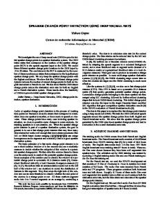
Schematic diagram of the theoretical system
E z Ž i , j, t q 1 .
Key words: free-space measurements; mine detection; FDTD; near-field measurements
y
Buried Objects
Ž1.
S. Biju Kumar ŽYoung Collaborator Programme . and C. K. Aanandan ŽAssociate Scheme . are thankful to the International Centre for Theoretical Physics ŽICTP ., Trieste, Italy, for financial assistance to visit ICTP and to carry out the theoretical work on FDTD.
⬁ ⬁ q 0 Ž i , j . q q y
E z Ž i , j, t . ty1
1
⬁ q 0 Ž i , j .
Ý
E z Ž i , j, t y m . ⌬ m Ž i , j .
ms 0
dt Ž ⬁ q 0 Ž i , j .. 0 dx dt Ž ⬁ q 0 Ž i , j .. 0 dy
Ž H y Ž i q 1, j, t . y H y Ž i , j, t .. Ž H x Ž i , j q 1, t . y H x Ž i , j, t .. Ž3.
where 0 Ž i, j . s Ž s y ⬁ .Ž1 y expŽydtrt 0 .. is the susceptibility function, ⌬ mŽ i, j . s Ž s y ⬁ . expŽymdtrt 0 .Ž1 y expŽydtrt 0 .. 2 , s is the static permittivity of the dielectric, ⬁ is the optical permittivity of the dielectric, t 0 is the relaxation time of the dielectric, and 0 is the permeability of free space. A Gaussian pulse with dt s 16.667 ps, T0 s 41.667 ps was executed at the source plane. A Yee cell was constructed from 140 grids in the X-direction and 80 grids in the Y-direction with a grid spacing dx s 0.5 cm and dy s 0.5 cm, respectively. Mur’s boundary conditions w5x were applied at the boundaries. A dielectric object Ž s s 4. of dimensions 3 cm = 3 cm was placed at a distance of 8 cm from the air᎐dielectric interface, as shown in figure 1. The response of the Gaussian pulse with time was noted. The same procedure was repeated with one more object placed at a distance of 18 cm away from the front surface, in line with the first object. P1, P 2, and P3 were three test points selected for study. The time-domain response from these points gives information on the buried object. This is explicit from Figure 2Ža., Žb.. Figure 2Ža. is the response obtained with a single object buried in the vessel, and Figure 2Žb. is that when two objects are in a line. The dotted line represents the response at point P1, and the solid line that at P 2 and P3. Peak R1 corresponds to the forward-moving Gaussian pulse, and R2 the
MICROWAVE AND OPTICAL TECHNOLOGY LETTERS / Vol. 31, No. 1, October 5 2001
45
3. EXPERIMENTAL SETUP AND RESULTS
1.2
Experiments were performed in the X- and Ku-bands. A cubical vessel of dimensions 40 cm = 40 cm = 35 cm was filled with dry sand Ž s s 2.5.. The pyramidal horn antenna which was connected to one port of the S-parameter test set transmitted 10 mW power, and the same antenna received the reflected power from the vessel. The X-band horn antenna has a half-power beamwidth ŽHPBW. of 18⬚ Ž E-plane. and 15.5⬚ Ž H-plane. and aperture dimensions 9.8 cm = 7.5 cm. The respective values for the Ku-band horn antenna are 20⬚, 17⬚, and 5.7 cm = 4.4 cm. Both of the antennas have a gain of ; 15 dB. A dielectric block Ž r s 4. of dimensions 7 cm = 3 cm = 3 cm was buried at a distance of 8 cm from the front surface of the vessel. Then the pyramidal horn antenna was set at each position P1, P 2, and P3 Žnear-field points., as shown in Figure 3. The time-domain response was plotted with an HP 8510 C vector network analyzer. The same procedure was repeated, with one more object buried at a distance of 10 cm behind the first object. The results obtained are shown in Figure 4. Figure 4Ža., Žb. represents the response obtained for single object in the X- and Ku-bands, respectively, and Figure 4Žc. gives the response of two objects in the Ku-band. In the figures, R1 is the reflection from the front surface of the vessel. R2 corresponds to the reflection from the first object, and R3 that from the second object. The dotted line represents the time-domain response of the Gaussian pulse corresponding to point P1, and the solid lines corresponding to P 2 and P3. The minor peaks appearing in front of R1 may be due to the discontinuities in the cables and connectors. A comparison of the theoretical and experimental results is shown in Table 1.
1.0 R1 0.8
Amplitude
0.6 0.4 0.2 R4 0 R2
R3
-0.2 0.5
1
1.5
2
2.5
3
3.5
4
Time, ns (a) 1.2 1.0 R1
Amplitude
0.8 0.6 0.4 0.2 R4
R6
0
0.5
1
1.5
R5
R3
R2
-0.2
2
2.5
3
3.5
4
4.5
4. CONCLUSION
Time, ns (b) Figure 2 Theoretical time-domain responses. Ža. With one buried object. Žb. With two buried objects in line. ------ response at test point P1, ᎏᎏ response at points P 2 and P3
reflection from the air᎐dielectric interface. R3 represents the reflection from the first buried object, and R5 that from the second object. R4 and R6 are the signals obtained due to the smaller dimensions of the objects. This can be avoided if the sample dimension is greater than the width of the Gaussian pulse. In Figure 2Žb., the response after peak R6 is the repetition of the reflections.
Figure 3
46
A simple and accurate method of detecting buried objects in the time domain has been presented. The results are compared with FDTD simulation results. An ordinary pyramidal horn with moderate aperture and nominal gain is used for the measurement. This technique finds wide applications in the detection of buried objects like land mines, pipes, voids, etc. The work can be extended to determine the dielectric parameters of hidden objects. ACKNOWLEDGMENT
The authors express their appreciation for the constructive suggestions and discussions rendered by Dr. P. Mohanan, Department of Electronics, Cochin University of Science and Technology, during the course of this work.
Experimental setup
MICROWAVE AND OPTICAL TECHNOLOGY LETTERS / Vol. 31, No. 1, October 5 2001
TABLE 1
Comparison of Results from Theory and Experiment Theoretical Results Žfrom Fig. 2.
Experimental Results Žfrom Fig. 3.
8 cm Žfirst object.
Ž R2᎐R3.r2 ª 0.3705 ns Ž7.125 cm. a
Ž R1᎐R2.r2 ª 0.4117 ns, 0.465 ns Ž8.42 cm.Žaverage. a
18 cm Žsecond object.
Ž R2᎐R5.r2 ª 0.92855 ns Ž17.86 cm. a
Ž R1᎐R3.r2 ª 0.9254 ns Ž17.79 cm. a
Actual Depth
a
The velocity factor in the dielectric is incorporated.
1.2 R1
Relative Amplitude
1 0.8 0.6 0.4 R2
0.2 0 -0.2 15
16
17
18
19
20
21
22
Time, ns
(a)
REFERENCES 1. T.P. Montoya and G.S. Smith, Land mine detection using a ground-penetrating radar based on resistively loaded vee dipoles, IEEE Trans Antennas Propagat 47 Ž1999., 1795᎐1806. 2. K. Demarest, R. Plumb, and Z. Huang, FDTD modeling of scatterers in stratified media, IEEE Trans Antennas Propagat 43 Ž1995., 1164᎐1168. 3. K.S. Yee, Numerical solution of initial boundary value problems involving Maxwell’s equations in isotropic media, IEEE Trans Antennas Propagat AP-14 Ž1966., 302᎐307. 4. R. Luebbers, F.P. Hunsberger, K.S. Kunz, R.B. Standler, and M. Schneider, A frequency-dependent finite-difference time-domain formulation for dispersive materials, IEEE Trans Electromag Compat 32 Ž1990., 222᎐227. 5. G. Mur, Absorbing boundary conditions for the finite-difference approximation of the time-domain electromagnetic-field equations, IEEE Trans Electromag Compat EMC-23 Ž1981., 377᎐382.
1.4 䊚 2001 John Wiley & Sons, Inc.
R1
1.2
Relative Amplitude
1.0
FAR-FIELD PATTERN CALCULATION IN BODY-OF-REVOLUTION FINITE-DIFFERENCE TIME-DOMAIN ( BOR – FDTD) METHOD
0.8 0.6 0.4
R2
0.2 0 -0.2 15
16
17
18 Time, ns
19
20
21
Recei¨ ed 23 April 2001
(b) 1.4
ABSTRACT: In this paper, we present a far-field pattern calculation technique in the body-of-re¨ olution finite-difference time-domain (BOR᎐FDTD) method. Because the BOR᎐FDTD sol¨ es two- and half-dimensional problems, it has different features from the threedimensional FDTD method in the far-field pattern calculation. A monopole antenna fed by a coax is used to ¨ alidate the technique described in this paper. 䊚 2001 John Wiley & Sons, Inc. Microwave Opt Technol Lett 31: 47᎐50, 2001.
R1
1.2
Relative Amplitude
Wenhua Yu,1 Nader Farahat,1 and Raj Mittra1 1 Electromagnetic Communication Laboratory The Pennsylvania State University University Park, Pennsylvania 16802
1 0.8 0.6 0.4 R2
0.2
Key words: BOR; FDTD; near-to-far field transformation; monopole antenna
R3
0 -0.2 17. 5
I. INTRODUCTION
18. 5
19. 5
20.5
21. 5
Time, ns
(c) Figure 4 Experimental time-domain responses. Ža. With one buried object Ž X-band response.. Žb. With one buried object Ž Ku-band response.. Žc. With two buried objects Ž Ku-band response.. ------ response at test point P 1, ᎏᎏ response at points P 2 and P3
The numerical techniques based on the finite-difference time-domain ŽFDTD. algorithm applicable to general electromagnetic problems have grown in importance w1᎐5x. The BOR᎐FDTD has a great advantage over the three-dimensional FDTD for a rotationally symmetric problem w6᎐11x. It is well known that the three-dimensional near- to far-field transformation technique has been widely used to compute the far-field pattern in the FDTD simulations w4, 5x. Because
MICROWAVE AND OPTICAL TECHNOLOGY LETTERS / Vol. 31, No. 1, October 5 2001
47