C. M. Herr, N. Gu, S. Roudavsky, M. A. Schnabel (eds.), Circuit Bending, Breaking and Mending: Proceedings of the 16th International Conference on Computer-Aided Architectural Design Research in Asia CAADRIA 2011, 000–000. © 2011, Association for Research in Computer-Aided Architectural Research in Asia (CAADRIA), Hong Kong
CAD SOFTWARE AS CUSTOMISATION TOOLS Using FBS protocol coding scheme to understand the behaviour of mass customisers M POURMOHAMADI,1 JS GERO,2 and R SAUNDERS3 1. The University of Sydney, Sydney, Australia,
[email protected] 2. Krasnow Institute for Advanced Study, Fairfax, USA,
[email protected] 3. The University of Sydney, Sydney, Australia,
[email protected]
Abstract. This paper explores the use of CAD software as tools in mass customisation systems and discusses using protocol study methods to analyse the interactions between customers and customisation tools. Current uses of CAD software as customisation tools will be presented. The use of the Function-Behaviour-Structure coding scheme to analyse protocols from customisation sessions is discussed. A protocol from Puma footwear customisation is analysed using the LINKOgrapher software and the results presented. The paper concludes with a discussion on the utility of computational support tools to study designers/customers utilizing CAD tools for mass customisation. Keywords. Mass customisation, CAD, customisation toolkits, design protocol study, FBS coding.
1. Introduction Mass customisation is an emerging business strategy that aims to provide customers with customised products with near mass production efficiency (Pine, 1993). In recent years, a number of successful companies have been built around this business model, e.g., Ponoko, Shapeways, Freitag, offering personalised products and services to their customers (Kumar et al, 2007). In addition, leading companies such as Nike and IKEA have adopted mass customisation in parallel with their traditional mass manufactured product lines.
2
M. POURMOHAMADI, J.S. GERO AND R. SAUNDERS
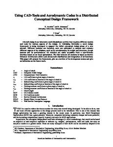
In construction and architecture industries, there have been efforts to adapt prefabricated buildings techniques to allow purchasers to customise a building by selecting and configuring components (Benros et al, 2007). From a technical perspective, companies have to adopt many advanced technologies such as CAD, rapid manufacturing and online sales to implement a mass customisation system (Helm et al, 2008). From a design point of view, they have to split the design decisions between a product’s designer and its end users. Companies make interfaces for customers to customise the product based on their preferences at points of purchase. In many cases these interfaces, known as customisation toolkits (Franke and Piller, 2003), are simplified CAD tools that guide users through typically huge solution space to the customers. Dimensions, functional features, colours and materials are some frequent decisions to be made by customers. For example, IKEA provides a simplified CAD tool (IKEA 2010) to assist its customers with planning their living spaces using a library of IKEA products, Figure 1.
Figure 1 – A screenshot from the IKEA Planner tool
The experience of involvement in the act of design is claimed to be enjoyable for the customers (Franke and Piller, 2004). However, some argue
CAD SOFTWARE AS CUSTOMISATION TOOLS
3
that performing the user-designer role leads to confusion of customers during customisation (Teresko, 1994). This phenomenon, called mass confusion, has been the focus of several customer-oriented researches in the field (Chen and Wang, 2010; Huffman and Kahn, 1998). Some have argued that CAD tools would not be as useful for customers as they are for designers since most customers don’t have the same knowledge and experience as designers do (Piller et al, 2005). As a result, overcoming mass confusion demands more than just providing users with sophisticated CAD toolkits. However, given the designerly nature of customisation (Pourmohamadi and Saunders, 2009), there is an opportunity to use methods and theories from design cognition studies to examine customers as designers with less, if any, design competency. In this paper, we discuss adaptation of protocol analysis methods from design studies to analyse the behaviour of customers in mass customisation. The results of a case study are presented and discussed to illustrate the usage and potential of this adaptation. 2. FBS Protocol Coding Scheme Protocol analysis is a well-established method for acquiring data on thinking from verbal reports (Ericsson and Simon, 1993). It has been used extensively in cognitive and behavioural studies of designers (Bilda et al, 2006; Ennis and Gyeszly, 1991). A typical protocol study consists of these tasks: 1. Coding development 2. Videoing designers 3. Transcription of video 4. Segmentation and coding 5. Analysis of coded protocol 6. Generation of linkograph 7. Analysis of linkograph
The FBS coding scheme (Kan and Gero, 2009) is driven by the FunctionBehaviour-Structure ontology of design (Gero, 1990). It categorises design activities using six variables (called design issues): Requirements, Function, Behaviour (expected and structural), Structure and Description. The final goal of designing is to transform a set of requirements (R) and functions (F) into a set of descriptions (D). The function (F) of an object is defined as its intended purpose or teleology. The behaviour of the design is either expected (Be) or derived from its structure (Bs). The structure (S) describes the components and their relations in the design. The requirements are variables that are not controlled by the designer but come from a client. There is no direct
4
M. POURMOHAMADI, J.S. GERO AND R. SAUNDERS
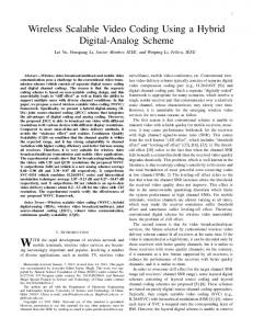
route from requirements and functions to descriptions and the designer has to go through cycles of transitional processes from one design issue to another. Figure 2 illustrates the eight transitional processes between design issues: Formulation which transforms functions into a set of expected behaviours (process 1); Synthesis, where a structure is proposed to fulfil the expected behaviours (process 2); an Analysis of the structure produces derived behaviour (process 3); an Evaluation process acts between the expected behaviour and the behaviour derived from structure (process 4); Documentation, which produces the design or partial design description (process 5). There are three types of reformulation: Reformulation 1 – reformulation of structure (process 6), Reformulation 2 – reformulation of expected behaviour (process 7), and Reformulation 3 – reformulation of function (process 8).
Figure 2: FBS issues and their transition processes (Kan and Gero, 2009)
The FBS based coding scheme converts a verbal design protocol into a series of segments where each segment addresses a single ontological design issue and is labelled by a single FBS code. After segmenting and coding the protocol, a linkograph is constructed by connecting segments based on their semantic relations (figure 3). The sequence of codes in a protocol along with its linkograph is the basis for a variety of analyses (Kan and Gero, 2008). The following section presents a case study of applying the FBS coding scheme to analyse the results of the use of the Puma footwear customisation system.
Figure 3: Part of a conceptual linkograph from a coded and linked design session.
CAD SOFTWARE AS CUSTOMISATION TOOLS
5
3. Case Study: Puma Footwear Customisation An exemplary case of customisation is presented here to discuss the method and potential of using the FBS coding scheme for analysing users’ behaviour during customisation of products. The task was to customise a pair of Puma shoes using their customisation tool (PUMA, 2010). The participant had no design related background or education. She was asked to verbalise her thoughts and decisions as she customised her shoes. The session lasted for 32 minutes until the participant described the final configuration as satisfactory. Following standard practice for producing data for protocol analysis, the recording of the customisation session was transcribed and coded using the FBS coding scheme twice by the same person with a ten day delay in between each coding session, to check the integrity of the coding. During customisation, the customer plays both client and designer roles. Consequently, one of the questions raised during the coding was how to define which segments are representing Requirement issues that come from client side. To resolve this conflict, we decided to consider any issues that are not the results of a process (e.g. Formulation) as Requirements. For example, if the participant verbalises the leather as preferred material without any prior analysis to decide on leather, the segment has been coded as Requirement. Both codes were then self-arbitrated with an 87% agreement using the Delphi method (Gero and Mc Neill, 1998). The final coded protocol consists of 372 segments including 300 FBS issues and 72 non-FBS segments. In other words, FBS coding was able to cover 81% of the protocol from the customisation session. This is a high degree of applicability, which could be due to similarities between the coded customisation case and general design activities. Table 1 shows an excerpt of the protocol and the code assigned to each segment. Table 1: An excerpt of the protocol and the code assigned to each segment. #
Utterance
Code
#
Utterance
Code
34
I don't want suede.
R
43
I want leather.
R
35
Because it's hard to look after
Bs
44
Because it’s nice and soft.
Bs
36
Black coffee grain leather.
S
45
And it can expand, too.
Bs
37
I don't want matte.
Be
46
OK. So, if I selected that.
S
3.1. BUILDING THE LINKOGRAPH Linkographs are built using semantic relations between design segments (Goldschmidt, 1990). From the ontological point of view, each link represents a transition process between two design issues (Gero et al, 2011). For example a link between a structure (S) and a description (D) segment de-
6
M. POURMOHAMADI, J.S. GERO AND R. SAUNDERS
notes the documentation process. The construction of the linkograph, like the coding, was done twice, ten days apart, to check the integrity of the relationships identified between segments. To build a linkograph, each segment is linked back to the prior segments that are semantically related to it. This linkograph is called the semantic linkograph to distinguish it from the syntactic linkograph that can be constructed by linking each segment only to its immediately preceding segment. The linkograph of the protocol is a rich dataset, which allows for a variety of statistical analyses. LINKOgrapher, an open-source analysis tool (LINKOgrapher, 2010), has been used to carry out the analyses in this paper. It performs common analyses measurements related to the FBS coding scheme on any formatted coded/linked protocol. The linking of the segments is carried out after removing non-FBS segments. There are a total of 755 semantic links in this protocol, i.e., an average of 2.52 links per segment. The following is an introduction of the common analysis methods and the results produced in this study. Since each link has a design issue at both ends it maps onto a design process. 3.2. FBS ISSUES AND PROCESSES DISTRIBUTION According to the FBS ontology, any design issue falls into one of the six codes and a non-FBS issue is not a design issue. Consequently, the density of design issues and processes in any given protocol is a measure of design activity in that case. One of the possible analyses on a coded protocol is to look at the distribution of the design issues and the design processes in that protocol. This is done by examining the overall distributions or dynamic distributions. In dynamic mode, a fraction of the protocol length is selected as a viewing and calculation window. The window is then moved forward along the length of the protocol one segment at a time and the distributions are calculated for each window position. Putting the results together produces a dynamic view of distribution of design issues and processes during the session. Table 2 shows the overall distribution of design issues as well as semantic and syntactic design processes in the protocol. In the case of Puma footwear customisation, the overall distribution of segments shows a high frequency of Structure (S) and Behaviour from Structure (Bs) issues in the protocol. This means the participant has tried and analysed many different configuration options during the session. The distribution of design processes also supports the same idea, with Analysis (19.3%) being the second most frequent process after Reformulation 1 (45.0%).
CAD SOFTWARE AS CUSTOMISATION TOOLS
7
Table 2: The distribution of design issues and processes in semantic and syntactic modes. Issue Requirement Function Exp. Behaviour Str. Behaviour Structure Description
Distribution (%) 2.7 1.3 12.0 24.3 48.7 11.0
Process Distribution Formulation Synthesis Analysis Evaluation Documentation Reformulation 1 Reformulation 2 Reformulation 3
Syntactic (%) 0.6 6.9 18.4 10.3 16.1 42.5 4.6 0.6
Semantic (%) 0.2 6.3 19.3 9.7 12.4 45.0 7.1 0.0
There is a high density of behavioural issues at the beginning (Figure 4), when the participant is listing her needs and preferences. After about 50 segments, the frequency of the structure issues begins to rise, i.e., the participant is trying many different possible options or basically clicking around. But after choosing the material for the quarters the frequency of behaviour issues increases. Dynamic process graphs also show a sharp increase in the frequency of reformulation-1 activities. In other words, the participant tries to match the behaviours of the selected configuration with her initial expected behaviours. Later we will show how information lack is observable at the same time, which is considered as one of the main sources of confusion.
Figure 4: Dynamic Design Issues Distribution in Puma Footwear Customisation Case
Figure 5: Distribution of Semantic Design Processes in Puma Footwear Customisation Case
8
M. POURMOHAMADI, J.S. GERO AND R. SAUNDERS
3.3. OVERALL AND DYNAMIC ENTROPIES In information theory, Shannon’s (1948) entropy is a measure of the information content of a message. Kan and Gero (2005) suggest entropy as a measure to analyse the potential of design sessions. Similar to design, here a non-linked linkograph means that the customer cannot make relations between the needs (expected behaviours) and the offered solutions (structures) (Piller et al, 2005). A fully linked linkograph happens when the customer knows everything about the offerings so there isn’t any new option (Huffman and Kahn, 1998). Though these conditions are not likely to happen in real world cases, they define the ground for our approach toward interpreting entropy of a mass customisation session. Qualitatively, there are two dramatic drops in the entropy graph of the customisation session shown in Figure 6. The first drop occurs around segments 70 to 90 when the customer is just clicking around and trying different options without any particular reasoning about or analysing those structures. This is close to the condition when there is no link between segments of a linkograph. The second drop occurs between segments 210 to 250. A look at the main events of the session will reveal that the participant is just reviewing the selected configuration, i.e., there are no new ideas being generated.
Figure 6: Dynamic horizonlinks entropy in Puma Footwear Customisation Case
There are a few local rises in the entropy graph as well. The sharpest increase happens around 120 to 150. This is when the participant is generating the main list of expectations for the future shoes and evaluating every configuration against those criteria. There is a high correlation (p = 0.01) between horizonlink entropy and the semantic distribution of design processes, Figures 5-6, i.e., the more the design activity, the greater the information lack the participant experiences. This suggests designerly issues in the customisation session as a potential cause of confusion. However, demonstrating a causal effect between design activity and knowledge insufficiency needs more in-depth analytical studies.
CAD SOFTWARE AS CUSTOMISATION TOOLS
9
4. Conclusion As companies shift from mass production to the mass customisation business strategy, they transfer the responsibility for making some design decisions to their customers. To facilitate this transformation, companies provide the users with customisation toolkits. In many cases, the customisation toolkit is a downgraded version of the CAD tool that designers use. Arguably, the customers do not have the design knowledge and experience to use such CAD tools the way designers do. Consequently, they end up being confused in making decisions about the product based on their personal needs and preferences. Appreciating the similarities between design and customisation, we suggested using methodologies from design studies to expand our understanding of the behaviour of customers in customization. In this regard, we chose the FBS coding scheme to analyse the protocols of the customer during customisation. The ontological foundation of this coding scheme allows for its application regardless of ground domain or number of participants. In this paper we presented a case study of Puma footwear customization using the FBS coding scheme. A non-designer participant was asked to customize a pair of shoes using the Puma configurator. The preliminary results of the analyses are promising as the coding scheme identified more than 80% of the total observed issues in the protocol. The models resulting from the analysis fit our qualitative observations and expectations. Applying the FBS coding scheme to the study of a single customization case generated promising results in its ability to provide insights into the behaviour of the customer while using CAD software to customise the product. Future studies will include coding and analyzing multiple cases of customization and aggregating the results to obtain statistically significant results. References Benros, D, Duarte, J.P. and Branco, F.: 2007, A system for providing customized housing: integrated design and construction using a computer tool, In Dong, A; Moere, A.V. and Gero, J.S. (eds), CAADFutures'7, Sydney, Springer, 153-166. Bilda, Z.; Gero, J.S. and Purcell, T.: 2006, To sketch or not to sketch? That is the question, in Design Studies, 27(5), 587-613. Chen, Z. and Wang, L.: 2010, Personalized product configuration rules with dual formulations: A method to proactively leverage mass confusion, in Expert Systems with Applications. Ennis, C. and Gyeszly, S.: 1991, Protocol analysis of engineering systems design process Research, in Engineering Design, 3(1), 15-22. Ericsson, K. and H. Simon: 1993, Protocol analysis: verbal reports as data, MIT Press. Franke, N. and Piller, F.: 2003, Key research issues in user interaction with configuration toolkits in a mass customization system: the foundation of the IDtown user design project, in International Journal of Technology Management, 26(5/6), 578-599. Franke, N. and Piller, F.: 2004, Value creation by toolkits for user innovation and design: the case of the watch market, in Journal of Product Innovation Management, 21(6), 401-415.
10
M. POURMOHAMADI, J.S. GERO AND R. SAUNDERS
Gero, J.S.: 1990, Design prototypes: a knowledge representation schema for design, in AI Magazine, 11(4), 26-36. Gero, J.S. and McNeill, T.: 1998, An approach to the analysis of design protocols, in Design Studies, 19(1), 21-61. Gero, J.S.; Kan, J.W.T. and Pourmohamadi, M.: 2011, Analysing design protocols: development of methods and tools, in ICoRD'11, India. Goldschmidt, G.: 1990, Linkography, in Cyberbetics and System '90, World Scientific. Helms, M.M.: 2008, Technologies in support of mass customization strategy: Exploring the linkages between e-commerce and knowledge management, in Computers in Industry, 59, 351–363. Huffman, C. and Kahn, B.E.: 1998, Variety for sale: mass customization or mass confusion?, in Journal of Retailing, 74(4), 491-513. IKEA: 2010, “IKEA kitchen planning tool”. Available from: http://www.ikea.com/ms/en_US/ rooms_ideas/kitchen/download1.html (accessed November 2010). Kan, J.W.T. and Gero, J.S.: 2005, Design behaviour measurement by quantifying linkography in protocol studies of designing, in Human Behaviour in Designing'05, Australia, Key Centre of Design Computing and Cognition, University of Sydney. Kan, J.W.T. and Gero, J.S.: 2008, Acquiring information from linkography in protocol studies of designing, in Design Studies, 29(4), 315-337. Kan, J.W.T. and Gero, J.S.: 2009, Using the FBS ontology to capture semantic design information in design protocol studies, in McDonnell, J. and Lloyd, P. (eds), About: Designing: Analysing Design Meetings, CRC Press, 213-229. Kumar, A., Gattoufi, S. & Reisman, A.: 2007, Mass customization research: trends, directions, diffusion intensity, and taxonomic frameworks, in International Journal of Flexible Manufacturing Systems, 19, 637–665. LINKOgrapher: 2010, “LINKOgrapher protocol analysis tool”. Available from: www.linkographer.com (accessed November 2010). Piller, F., Schubert, P., Koch, M. and Möslein, K., 2005. Overcoming mass confusion: collaborative customer co-design in online communities, in Journal of Computer-Mediated Communication, 10(4). Pine II, B.J., 1993. Mass customization: the new frontier in business competition, Harvard Business School Press, Boston. Pourmohamadi, M. and Saunders, R.: 2009, Designerly ways of customising, in Mass Customisation and product configuration (MCPC’9), Finland. PUMA: 2010, “PUMA Mongolian Shoe BBQ”.. Available from: mongolianshoebbq.puma.com (accessed September 2010). Shannon, C.: 1948, A mathematical theory of communication, The Bell System Technical Journal, 27, 397-423. Teresko, J.: 1994, Mass customization or mass confusion, in Industry Week, 243(12), 45-48.