1482
Schilling et al. / J Zhejiang Univ SCIENCE A 2006 7(9):1482-1491
Journal of Zhejiang University SCIENCE A ISSN 1009-3095 (Print); ISSN 1862-1775 (Online) www.zju.edu.cn/jzus; www.springerlink.com E-mail:
[email protected]
CAD-VR geometry and meta data synchronization for design review applications* SCHILLING Arne†1, KIM Seokryul2, WEISSMANN Daniel3, TANG Ziying1, CHOI Sangsu2 (1Fraunhofer Institute for Computer Graphics (IGD), Darmstadt 64283, Germany) (2Institute for Graphic Interfaces (IGI), Seoul 120-750, Korea) 3
( Computer Graphics Center (ZGDV), Rostock 18059, Germany) †
E-mail:
[email protected]
Received Feb. 28, 2006; revision accepted May 3, 2006
Abstract: In this paper we present the MEMPHIS middleware framework for the integration of CAD geometries and assemblies with derived Virtual Reality (VR) models and its specific meta data and attributes. The goal of this work is to connect real time VR applications, especially for the Design Review, with enterprise software storing and managing CAD models (Product Data Management—PDM). The preparation of VR models requires expert knowledge, is time consuming, and includes selection of required CAD data, tessellation, healing of unwanted gaps, applying materials and textures, and special surface and light effects. During the Design Review process, decisions are made concerning the choice of materials and surface forms. While materials can be switched directly on the VR model, the modification of part geometries must be made on the CAD model. Our system synchronizes modifications of the original CAD geometries and of attributes that are relevant for the realistic rendering using the PLM Services standard. Thus, repeated work for the VR preparation can be avoided. Key words: Virtual Reality (VR), CAD, Product Data Management (PDM), Geometry conversion doi:10.1631/jzus.2006.A1482 Document code: A CLC number: TP202
INTRODUCTION The first phases of the product life cycle are almost completely digitalized nowadays. Single parts or complete product models are modeled with 3D CAD solutions. Assembling single parts to digital mockups (DMUs) is important for checking the dependencies between the parts and detecting conflicts. Due to their complexity, such data is managed in specialized Product Data Management (PDM) systems. They gained an increasing importance in many industries during the last decade (Qiao and McLean, 2004). Currently they are extended to support more phases of the product lifecycle up to production and shop floor planning and are correspondingly called Product Lifecycle Management (PLM) systems *
Project supported by the Korean Ministry of Information and Communication (MIC)
(Nowacki and von Lukas, 2003). In industries concerning highly complex end consumer products, it is crucial not only to design the geometrical shape of the product parts using CAD workstations, but also to be able to review the interior and exterior before assembling the first prototype (Hur et al., 2006). Our aim is to support new 3D technologies for the Design Review process that are based on a high resolution real time 3D representation using realistic surface simulation (compare Fig.1). In comparison to desktop applications, such Virtual Reality (VR) systems using Head Mounted Displays and high resolution 3D displays can lead to a much better spatial understanding. Such displays are not able to process CAD data directly but need models composed of triangle sets (Graf et al., 2002). Usually PDM systems cannot manage meta data related to the VR files (e.g. light settings, materials, textures, and behaviors). They lack functionalities to
Schilling et al. / J Zhejiang Univ SCIENCE A 2006 7(9):1482-1491
maintain links between the meta data and the geometric models inside the VR files. Thus, the data exchange between PDM (or CAD) and VR systems concentrates on geometrical data. VR-specific information has to be added manually each time the CAD models are converted to VR data.
1483
one computer. The VR data, which is needed to present 3D models of future products in real time and high quality, can be produced directly from CAD and PDM systems. VR systems can be initiated using the original CAD sources that are used to plan and build the product.
PLM SERVICES
Fig.1 Material manipulation of a VR model, provided by MEMPHIS, in a VR system (in-house solution TiciView, image source: Hur et al., 2006)
Research activities concentrate so far on the exchange of geometry information between CAD and VR systems. The exchangeability of product meta data is still neglected. Thus, fundamental information such as material, structural information etc. from the original CAD data is not incorporated in the VR environment. A major obstacle, as pointed out by Corseuil et al. (2004) is the CAD data’s file size which can be too large and complex to be visualized in real time. Special care must be taken when assembling digital mockups from several files. Gomes de Sá and Zachmann (1999) presented several interaction paradigms and functionalities which a VR system must implement in order to be suitable for that application area. They aim on enabling inexperienced users to work with virtual prototypes in an immersive environment and help them experiment efficiently with CAD data. The MEMPHIS (Middleware for Exchanging Machinery and Product Data in Highly Immersive Systems) to be introduced in this paper synchronizes geometry as well as structure and meta data between the VR and the CAD/PDM system. It takes care of the communication and data management within the design workflow of a company. Relying on Web service technology and OMG PLM Services, VR data no longer has to be stored and processed only locally on
Although the integration of product management in the IT environment within a company can be complicated enough, large enterprises face an even more challenging task. They need to harmonize PDM systems installed at different branches, subcontractors and OEM providers. This is necessary in order to foster the digital co-operation and exchange of product data. The first step to achieve this goal was the introduction of a common data format, which is ISO 10303 STEP (Standard for the Exchange of Product Model Data). Various Application Protocols (APs) are specialized for describing e.g. mechanical parts, electronic parts and others. A promising approach is to establish online communication protocols for synchronous and asynchronous data exchange. Instead of proprietary connectors a common interface is introduced that covers as much functionality of PDM systems as possible. Even the federation of systems seems to be feasible as described by e.g. Krause et al. (2003) and Nowacki and von Lukas (2003). We use the international standard “PLM Services” for managing product related content and for the data exchange with existing PDM systems. The standard has been developed by the XPDI taskforce of the ProSTEP iViP association (von Lukas and Nowacki, 2005). In April 2004 it has been accepted by the Object Management Group (OMG). The standard is completely compliant with STEP AP214 and defines an abstract platform independent model (PIM). From this specification concrete implementations are derived (Feltes et al., 2004). We use the platform specific model (PSM) for XML Webservices. The PIM informational model consists of the following packages: Alias_identification, Authorization, Change_and_work_management, Classification, Configuration_management, Document_and_ file_management, Multi_language_support, Part_ identification, Part_structure, PLM_base, Process_
1484
Schilling et al. / J Zhejiang Univ SCIENCE A 2006 7(9):1482-1491
planning, Properties, Shape_definition_and_transformation. From these packages we selected the following as a basis for implementing the database and the communication protocol between the MEMPHIS components and PDM systems: PLM_base, Part_ identification, Part_structure, Document_and_file_ management, Properties, and Authorization.
with other systems or components e.g. PDM systems, VR systems, the database (DB), the CAD2VR Converter or the Security Component (Fig.3). The main components used in the MEMPHIS system are listed in Table 1 and will be described in more detail in the following chapters. CAD System 1
VR System 1
SYSTEM OVERVIEW
CAD System 2
VR System 2
MEMPHIS is data exchange middleware that allows centralized communication between multiple CAD and VR systems via a PDM system. It consists of a server implementation accessed by a client. Other systems (e.g. PDM and VR systems) will be attached by adaptors. Using this system, the communication and the exchange of data will be unified. In form of the adaptors, it will provide common interfaces that rely on international standards for PDM product structures and the transmission of data (PLM Services) and enable a centralized integration of multiple PDM systems (server) from any point (clients). A database represents the product structure introduced by PLM Services and is part of the system. This will allow tracking meta data and its connection to geometrical data by storing and maintaining this information. Even after changes were made to the 3D model, the VR-specific meta data will automatically be re-inserted to the VR file. Thus, the problem of repeated manual efforts for this integration will be solved. As a centralized middleware technology, MEMPHIS is specialized on the consistent management and the reusability of VR information related to the CAD data. Thus, it allows centralized conversions from CAD to VR formats, the management and manipulation of the semantic product structure and the extension of this structure with VR specific information (Fig.2). This information is reusable even after subsequent conversions, as the MEMPHIS system keeps track of changes and attachments in the data structure. Furthermore, the efforts for the users to create the virtual scenes are widely reduced, as most of the tasks can be automatically or semi-automatically accomplished by the MEMPHIS system. The MEMPHIS system consists of several sub-components. Each component has a relationship
CAD System 3
VR System 3
CAD System1
VR System1
CAD System2
VR System2
CAD System3
VR System3
(a) CADCAD System 1 System1
PDM system
VR VR System 1 System1
MEMPHIS system
CADCAD System 2 System2
VR VR System 2 System2
CADCAD System 3 System3
VR VR System 3 System3 System interface
(b) Fig.2 Data management in the Meta Data Server. (a) A common data exchange method; (b) The proposed data exchange method in MEMPHIS Engineering Data Resource PDM System 1 PDM System 2 PDM System 3 DB DB
PDM Adapter
CAD2VR Converter CAD2VR Converter
MEMPHIS Server MEMPHIS Server File Server Meta Data Server File Server Meta- Data Server
Security Component Security Component
SOAP Messages based on PLM Services
DB DB
Security Component Fire Wall
MEMPHIS Client MEMPHIS Client VR Adapter VR System 1 VR System 2 VR System 3 VR System1 VR System2 VR System3 VR Environment
Fig.3 Overall architecture of the MEMPHIS system Table 1 MEMPHIS consists of the following components Component
Task Management of stored product meta Meta Data Server data Management of file data such as File Server CAD and VR data Serialize and de-serialize communiMEMPHIS Client cation from and to the server Data exchange component between the MEMPHIS system and PDM PDM Adapter systems Data exchange component between the MEMPHIS system and VR VR Adapter systems Data conversion component from CAD2VR Converter CAD to VR data Security Component Access rights management
Schilling et al. / J Zhejiang Univ SCIENCE A 2006 7(9):1482-1491
Each relationship among components or to other systems is accomplished by adaptors or internal connectors. Adapters are used to make a connection to external systems such as PDM systems or VR systems. They make use of two kinds of methods. The first method is to include a sub-application using batch calls to start the related functionalities. The second method is the usage of public libraries which can be integrated into the system on the source level. Internal connectors are used to make a connection with internal components such as the DB, the CAD2VR Converter or the Security Component. These internal connectors are embodied as source based components, as their functionalities are integrated as class libraries. This paper will concentrate on the adapters, since the relevant processes are not related to the functionalities of the internal connectors. The adapters have a key role for the data exchange between PDM and VR systems. Meta data server The Meta Data Server manages the meta data of a product, e.g. the Bill of Materials (BOM), level of detail for the product model data (LOD) as well as other VR related property data. This server represents the major difference of the data management compared to other engineering data management servers like PDM systems or drawing management systems. It enables the parallel management for CAD and VR data. Generally, most of the management systems take care of CAD data as the most important information. Although they are able to store VR files, these systems cannot handle various VR specific information such as LOD, textures, shaders, etc. For this reason, they cannot be integrated sufficiently with VR environments. File formats usable for VR have to be converted manually. VR specific information has to be added after each conversion and cannot be reused. The Meta Data Server can manage CAD and VR data more equally than other engineering management systems. All data is stored and managed as Data Management Containers (DMC) based on the PLM Services specification (Fig.4). A DMC can be divided into six data management layers: Person, Organization, Project, Item, Document and Property. Internally all data layers are linked as a tree structure and each data layer has a 1:n relationship for the related data layer. With these containers the complete structure of a product and its relations can be represented. This includes arbitrary meta data, attached to the geometrical information as properties.
1485
Data Management Containers (DMC) …
…
…
…
…
… • Property Property • Document Document • Item Item • Project Project Organization • Organization Person • Person
(a) Person 1:n Organization 1:n Project 1:n Item 1:n Document 1:n Property
(b) Fig.4 Data management in the Meta Data Server. (a) Data management container; (b) Hierarchy of data management layers
Due to this shared data structure, requests for geometrical VR data can be connected with requests for the VR-specific meta data. Both sources can be integrated into one output file. The underlying database, which represents the structure, is also used to allow keeping track of changes. If a geometry item is modified or the product structure itself is changed, the affected properties and information stay connected to its logical location. Thus, by reading out the information from the database, requests for VR data will result in correctly formed files including all expected meta data. File server The File Server is responsible for storing and delivering the actual physical files. It has been separated from the Meta Data Server due to the possible high workload when providing large datasets in a multi user environment. Some additional information is also stored like file size, file type, file creation date, etc. Additionally, the File Server can also operate the integrated CAD2VR Converter. The CAD2VR Converter is used to convert CAD files to VR files such as VRML (Virtual Reality Modeling Language) and X3D (eXtensible 3D). Thus the MEMPHIS Client can perform remote file conversion by handling the File
1486
Schilling et al. / J Zhejiang Univ SCIENCE A 2006 7(9):1482-1491
Server from the client side (Fig.5). The benefit of this server lies in the centralized handling of the files (VR, CAD) even if no data structure is provided or needed. This allows the use of the MEMPHIS functionalities and its services for single files.
Physical VR Files
File Meta Data
File File DB DB
(VRML, X3D)
MEMPHIS Server
CAD2VR Converter CAD2VR Converter (InterOp) ( InterOp)
FileFile Server Server
Physical CAD Files
Fig.5 File Server in the MEMPHIS system
MEMPHIS Client and VR Adapter The purpose of the MEMPHIS Client is to provide a well defined interface to the system’s functionalities for the user. By restricting the access to the MEMPHIS data exclusively through the client implementation, a controlled data exchange can be guaranteed. This control includes authorization checks of the user and secure data wrapping of the exposed information. This also leads to a more convenient operation for the user who has not to take care of internal data type matching, connection protocols etc. The MEMPHIS Client’s main features are: (1) Secure exposure of data by wrapping of the internal data structure; (2) Simplified data structure management and manipulation using functions of the client, including: (a) Managed object structure; (b) Functions for loading data from and writing data to server; (c) Creating new and editing existing data; (d) Manipulation of the data’s tree structure; (3) Hiding the complex data structure of the MEMPHIS database; (4) Integrated authorization check including login, allowing requests to server only to authorized users. The implementation features a stand alone version of the client, providing a user-friendly graphical interface for managing and manipulating information from the server. Furthermore, a library version (VR Adapter) of the client can be used to integrate the MEMPHIS Client interface inside other applications (e.g. VR systems) giving direct access to its functionalities. Using the VR Adapter instead of the stand alone client offers extended flexibility especially for VR applications. The featured data structure allows the
integration of arbitrary properties into the semantic structure of the virtual models. This extends the scope of CAD properties and enables the addition of attributes such as 3D shaders, events, animation sequences or behaviors. As this information is stored on the server side and tracked in case of changes in the structure or geometrical information, the VR Adapter leads to a high degree of reusability of additional VR data. This data is not supported in CAD or PDM systems and commonly has to be added manually after each changes made in the original data. PDM Adapter CAD models made by many different commercial CAD systems are stored and managed within PDM systems and must be transferred to the MEMPHIS system. In order to do that, there is a strong need to develop an integrator between diverse PDM systems and the MEMPHIS system. For this purpose a PDM Adapter is being developed. Particularly, it is composed of the PDM Connector and the MEMPHIS Connector. These sub-components are developed to conform the PLM Services specification. The PDM Connector is directly connecting to the PDM system. Usually, most of the commercial PDM systems (e.g. TeamCenter, ENOVIA, WindChill, etc.) are providing their own API (Application Programming Interface) to customize their provided services from the PDM Server (TeamCenter Engineering, 2003). In order to connect to a commercial PDM system, the provided API is used. The objects and methods are mapped to the XML elements defined in the PLM Services specification to implement a common interface for the PDM data (Fig.6). In this context, common interface means a sharable neutral file between PDM and the MEMPHIS system. After creation of the common interface, the MEMPHIS Connector can be used for data parsing and data transmission to the MEMPHIS server via SOAP messages. For a newly integrated PDM system only the Connector to its API has to be implemented. The MEMPHIS Connector can be used for all connected systems. Up to this point, the description of the data flow covers only the direction from PDM to the MEMPHIS system. The PDM Adapter can further be used to transfer data in the opposite direction. To transmit data from MEMPHIS to the PDM system, the MEMPHIS Connector that provides the common interface in form of a neutral file can also be utilized
Schilling et al. / J Zhejiang Univ SCIENCE A 2006 7(9):1482-1491
while the PDM Connector is performing the data parsing and data transmission to the PDM server via the PDM API. PDMPDM Server Server PDM PDM 1 1
PDM PDM 2 2
PDM Adapter MEMPHIS MEMPHIS Server Server
PDM PDM 3 3
PDM APIs
PDM PDM Connector Connector MEMPHIS MEMPHIS Connector Connector
MEMPHIS MEMPHIS Server Server
Common Interfaces based on PLM Services
Fig.6 PDM Adapter in the MEMPHIS system
CAD2VR Converter For the conversion of CAD formats to VR compatible files, the CAD2VR Component is integrated. On request by the MEMPHIS Server the CAD2VR Converter processes the CAD data conversion and performs automated corrections of geometry and topology. These corrections are necessary in order to get visually correct results. As to geometry or topology changes, the current version of the component includes tessellation/triangulation functions for NURBS, LOD generation and the calculation of vertex normals. For the generation of VR data from CAD data, we use the InterOp of the ACIS CAD kernel from Spatial Corporation (ACIS R15, 2005). The ACIS CAD kernel is an object oriented three dimensional geometric modeling engine and it provides an open architecture framework for wireframe-, surface- and solid-modeling using a common, unified data structure. The CAD2VR Converter supports CATIA V4/V5, Unigraphics, and Pro/Engineer. As possible neutral file formats, STEP (AP203) and IGES (Initial Graphics Exchange Specification) are supported as well. That allows a broad base for the generation of VR files (VRML, X3D) from tessellated CAD geometry models. For the CAD2VR Converter we implemented the following process chain (Fig.7). CAD part files are loaded using the Spatial InterOp libraries. They translate various formats into the internal ACIS kernel model. On this model 3 different correction mechanisms can be applied. The necessity depends on the source file and the way it has been modeled. (1) Stitching refers to the reconstruction of topology information. The topology can be broken when loading some exchange formats (e.g. IGES), which causes problems during the tessellation phase.
1487
In this case it has to be reconstructed by analyzing the vicinity of the edges of surface elements. (2) Gap Healing refers to the geometrical correction of edges which are spatially apart but should actually lie exactly on each other. For detecting such gaps a spatial filter is applied to the model using a certain tolerance. Edges with a distance smaller than this value will be collapsed into one. The computation of the tolerance value is crucial since elements (also NURBS) smaller than this value will be removed completely. It also determines the size of the smallest detail. Thus, it will be later used as preprocessing step for the Generalization. (3) In the Normal Correction phase the surface orientation is corrected. Incorrect normals can occur when creating CAD surface models, e.g. for the outer hull of a product. While not being a problem for NC software, real time visualization toolkits may produce incorrect lighting simulations. Impor Import
Tessellation Tessellation
t
Input Input CAD CAD File File
ACIS ACIS Kernel Kernel
Encoding Encoding
OpenSG OpenSG Scenegraph Scenegraph
Output Output VR VR File File
Output Output CAD CAD File File
Fig.7 The process chain of the conversion from CAD to VR files contains steps for geometry correction and data translation
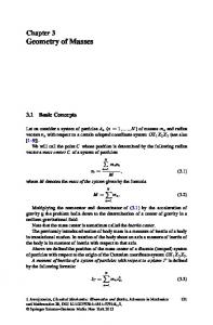
After these optional corrections based on the CAD model, a VR model will be generated by tessellating all NURBS and parametric surfaces. For the tessellation, we use the ACIS Faceter component. It provides several input parameters which control the final surface quality and the number of generated triangles. The most important parameters are: Normal tolerance: maximum angle between surface normals of two adjacent surfaces; Surface tolerance: maximum distance between the original and the tessellated surface; Maximum edge length of the generated facets; Maximum grid lines per NURBS; Grid aspect ratio of generated triangle. The resulting meshes are translated into a scenegraph representation which is based on OpenSG. Fig.8 shows the results of stitching and normal correction processes in our OpenSG viewer. The most important CAD entities are translated
1488
Schilling et al. / J Zhejiang Univ SCIENCE A 2006 7(9):1482-1491
CAD part file
Mesh as attachment
BOD BODY Y LUM LUMP P
CMPar CMPart t
SHEL SHELL L
CMBod CMBody y WIR WIRE E
FAC FACE E LOO LOOP P
(a)
(b)
COEDG COEDGE E EDG EDGE E VERTE VERTEX X
CMWir CMFac CMFace CMWire e e GeoPosition3 GeoPosition3f f GeoIndicesUI32 GeoIndicesUI
32 GeoPType GeoPTypes s GeoPLengrh GeoPLengrhs s
Fig.9 Translation of the entities from the ACIS CAD model (left) into the internal VR model based on OpenSG. The Faceter module attaches the generated mesh to the FACE. It is then translated into OpenSG typical vertex and index lists (c) Fig.8 Stitching and normal correction. (a) Uncorrected model at low quality level (normal tolerance 30°), artifacts between FACEs are visible; (b) Corrected model at the same quality level; (c) Corrected model at higher quality level suitable for VR (normal tolerance 10°)
into according to OpenSG objects, which can be combined to more complex digital mockups. The basic CAD entity describing a single surface (mostly NURBS) is the FACE. WIREs are used to represent 1-cell primitives. FACEs and WIREs are combined to SHELLs representing the outside of a solid or an internal void (hollow). The next aggregation levels are LUMP (a solid that is bounded by SHELLs) and BODY (consisting of one or several disjoint LUMPS). Normally a CAD file contains a list of many BODYs that are managed using IDs, names, layers, colors, annotations, and other tags. In the OpenSG model we concentrate on FACE, WIRE, BODY and PART (representing one CAD part file, e.g. CATIA V5 CATPart). SHELLs and LUMPs are neglected, since they have no relevance in the visualization model being the final output of the conversion process. LOOPs, COEDGEs, EDGEs, and VERTEXs are combined to meshes by the Faceter and are attached to the FACEs. Fig.9 shows the comparison of the original ACIS CAD topology model and the OpenSG scenegraph model. The OpenSG scenegraph will be also the basis for more complex computations like Generalization and Visibility Check (detecting global visibility and removing hidden elements in order to reduce the model complexity), which are not discussed within this paper, since they are in a preliminary stage.
During the third step in the process chain, the OpenSG scenegraph is encoded as X3D or VRML file, which is the final output of the CAD2VR Converter module. However, the property management of MEMPHIS is bound to physical files. Properties are attached to documents. For the intermediate OpenSG model we need to define a material for each geometry. On the other side, CAD assemblies contain usually many parts, each of them stored in individual files and having one material. Therefore, we accumulate all GeoPositions3f, GeoIndicesUI32, GeoPTypes, and GeoPLengths fields and generate one geometry per file. The appearance of the resulting X3D/VRML part file can be much easier modified using properties as meta data in MEMPHIS. WORK FLOW PDM systems can manage CAD data of various types. At that point, the user connects with a PDM system via MEMPHIS to obtain the CAD data instead of establishing a direct connection to the PDM system. Here we will give a description of work steps and the data flow in the MEMPHIS system. Fig.10 shows the described work flow. Step 1: CAD data acquisition from PDM system: the physical CAD file and CAD-specific meta data are acquired from the PDM system via the PDM Adapter utilizing the PDM Connector which is specialized to the specific PDM system. Step 2: Data storing: the acquired data is stored to the File Server’s DB which keeps the CAD files
Schilling et al. / J Zhejiang Univ SCIENCE A 2006 7(9):1482-1491
Engineering Data Resource PDM System 1 PDM System 2 PDM System 3 PDM System1 PDM System2 PDM System3 DB DB
1
3 2
MEMPHIS Server MEMPHIS Server File Server Meta Data Server File Server Meta- Data Server
CAD2VR Converter CAD2VR Converter 3 Security Component Security Component
2
4
2
DB DB
2
Security Component Security Component Fire Wall
MEMPHIS Client MEMPHIS Client 5 VR System 1 VR System 2 VR System 3 VR System1 VR System2 VR System3 VR Environment
Fig.10 Work flow in the MEMPHIS system
and the Meta Data Server’s DB which keeps the semantic product structure and integrates meta data such as the BOM information into this structure. Step 3: Data conversion from CAD to VR: stored physical CAD files are converted to physical VR file by the CAD2VR Converter. Optionally LOD settings can be made. The converted VR file is also stored in the File Server’s DB. Step 4: Communication between the MEMPHIS Server and the MEMPHIS Client: stored data on the sever side which was acquired through the above Steps 1~3, can be manipulated (data search, addition, elimination and renewal) by end user’s requirement on the client side. To do this manipulation, the MEMPHIS Server (the File Server and the Meta Data Server) and the MEMPHIS Client communicate in a distributed computing environment via SOAP messages. Step 5: Data manipulation in VR systems: in the MEMPHIS architecture, the VR system is introduced to create enriched VR data and to visualize this data. With the VR Adapter, the MEMPHIS Client has a connection with the system to get the VR file which was converted from CAD data in Step 3. Also the related meta data which include LOD information, BOM information for geometry model data can be loaded. Changes made on the client side can include attachment of new or changed properties to the product structure. By updating these changes to the server and into the meta data database, they are integrated in the product’s structure.
SAMPLE APPLICATION This chapter shows the practical use of MEM-
1489
PHIS as an integrated component of the design process. As a sample for a network using the MEMPHIS system, we used TeamCenter, the PDM solution of UGS. Further an in-house VR manipulation tool (TiciPrep) is connected on the VR side of the system. TiciPrep concentrates on applying and managing materials and hardware Shaders to virtual models. Shaders are used to generate realistic reflections, refraction, bump mapping, BRDF behavior, and other surface effects. As a VR viewer with 3D interaction possibilities, the OpenSG based engine AICI (Hur et al., 2006) is used, which is also an in-house solution. As shown in Fig.11, the CAD information can be processed for VR presentation in a sequential manner. Commonly, after the conversion of CAD files to VR files, additional settings would have to be added by a programmer. Depending on the VR format, material settings are included to the geometry nodes, scripts for behaviors are added as well as animation information, etc. If changes have been made to the original CAD models and this data is again converted to the VR format, all inclusions have to be made again. Even if the blocks of code are stored separately to be reused, the correct integration costs high efforts repeatedly. Using the middleware MEMPHIS, these efforts are not required anymore, as shown in the following example. The data in TeamCenter or on the MEMPHIS Server can be requested by the user of TiciPrep either internally with the VR Adapter or with the stand alone client (Fig.12). Through the MEMPHIS Client implementation, the required project and sub-items of interest can be selected. This includes already integrated VR properties. Settings for the conversion can be made. The request is processed by the MEMPHIS server. If the original data is in the PDM system and not stored in the MEMPHIS database, it will be accessed through the PDM Adapter. The specified conversions are performed by the CAD2VR component and the selected properties from the database are added to the resulting VR file. This file is then sent back to TiciPrep. In TiciPrep, VR specific properties such as high quality shaders can be added or changed. At the end of the process these changes can be written back to the MEMPHIS Server for future access for e.g. TiciView (Fig.1).
1490
Schilling et al. / J Zhejiang Univ SCIENCE A 2006 7(9):1482-1491
(a)
(b)
(c) Fig.11 Data conversion process in the MEMPHIS system. (a) CAD data stored in a PDM system (TeamCenter, abstract view); (b) Converted data (CAD to X3D) in the MEMPHIS system; (c) Enriched data in a VR system (TiciPrep)
interoperability between CAD/PDM and VR systems. It serves as a VR/CAD data hub that supports the early design phase in which the physical/mechanical design using CAD on the one hand and the visual design using realistic VR on the other hand are defined. We demonstrate how the international standard “PLM Services” can be used as an informational model for establishing this connection, together with X3D, OpenSG and the ACIS CAD kernel. MEMPHIS reduces redundant work steps since it maintains VR specific information that can be written back by VR tools. Otherwise, all conversion steps and application of VR data must be carried out again if the original CAD parts are modified. This saves time and efforts especially in the industries in which virtual prototypes are used for simulation, virtual manufacturing, and design review. It potentially further shortens the time-to-market periods for new products. Since most of the companies in the manufacturing industries are using PDM systems, it is crucial for this kind of middleware to be able to connect to them via adaptors. In the current development status, the system has been implemented for one PDM (TeamCenter) and one VR system (TiciPrep/TiciView) in order to show the proof of concept. Later it can be extended with less effort than implementing direct system-to-system interfaces. Adapters for arbitrary commercial or noncommercial PDM and VR systems can be introduced following the schema provided by the MEMPHIS system, making it a highly flexible tool within the production process.
ACKNOWLEDGEMENT The presented work is part of the joint research project “Intelligent Manufacturing Systems” (IMS). It is carried out by IGI, ETRI and INI-GraphicsNet members. References Fig.12 Graphical user interface of the MEMPHIS client
CONCLUSION In this paper we showed the feasibility of a data exchange middleware that significantly improves the
ACIS R15, 2005. Online Help. Spatial Corporation. Corseuil, E.T.L., Raposo, A.B., da Silva, R.J.M., Pinto, M.H. G., Wagner, G.N., Gattas, M., 2004. ENVIRON— Visualization of CAD Models in a Virtual Reality Environment. Proceedings Eurographics Symposium on Virtual Environments, p.79-82. Feltes, M., Habel, P., Lämmer, L., Nowacki, S., Staub, G., 2004. Product Lifecycle Management Service Revised Submission. OMG document number mantis/2004-04-01,
Schilling et al. / J Zhejiang Univ SCIENCE A 2006 7(9):1482-1491
http://www.prostep.org/file/13580.plm-serv10. Gomes de Sá, A., Zachmann, G., 1999. Virtual reality as a tool for verification of assembly and maintenance processes. Computers & Graphics, 23(3):389-403. [doi:10.1016/ S0097-8493(99)00047-3]
Graf, H., Brunetti, G., Stork, A., 2002. CAD2VR or How to Efficiently Integrate VR into the Product Development Process. CAD 2002 Proceedings. Corporate Engineering Research, Bonn, p.249-258. Hur, H., Fleisch, T., Kim, T, On, G., 2006. AICI—Advanced Immersive Collaborative Interaction Framework. Proceedings of Korean CAD/CAM Conference, Phoenix Park, Korea. Krause, F.L., Hayka, H., Pasewaldt, B., 2003. Supporting Coll-
1491
aborative Processes by the Federation of Product Data Management Systems. Science Days 2003, Dresden. Nowacki, S., von Lukas, U., 2003. Efficient and Collaborative Federation of Product Data. Science Days 2003, Dresden. Qiao, G., McLean, C., 2004. Manufacturing Information Integration in Product Lifecycle Management (PLM). Proceedings of DETC’04 ASME 2004 Design Engineering Technical Conferences and Computers and Information in Engineering Conference, Salt Lake City, Utah. TeamCenter Engineering, 2003. Online Help Collection. UGS Corporation. von Lukas, U., Nowacki, S., 2005. High Level Integration Based on the PLM Services Standard. ProSTEP iViP Science Days 2005: Cross-Domain Engineering, p.50-61.