CAPE-OPEN Integration for Advanced Process Engineering Co-Simulation Stephen E. Zitney National Energy Technology Laboratory Morgantown, WV 26507-0880
[email protected] http://www.netl.doe.gov Paper 535a, Session: TD001 Cape-Open Unit Operations: Development and Usage AIChE 2006 Annual Meeting, November 12-17, San Francisco, CA
ABSTRACT This paper highlights the use of the CAPE-OPEN (CO) standard interfaces in the Advanced Process Engineering Co-Simulator (APECS) developed at the National Energy Technology Laboratory (NETL). The APECS system uses the CO unit operation, thermodynamic, and reaction interfaces to provide its plug-and-play co-simulation capabilities, including the integration of process simulation with computational fluid dynamics (CFD) simulation. APECS also relies heavily on the use of a CO COM/CORBA bridge for running process/CFD co-simulations on multiple operating systems. For process optimization in the face of multiple and some time conflicting objectives, APECS offers stochastic modeling and multi-objective optimization capabilities developed to comply with the CO software standard. At NETL, system analysts are applying APECS to a wide variety of advanced power generation systems, ranging from small fuel cell systems to commercial-scale power plants including the coal-fired, gasification-based FutureGen power and hydrogen production plant. INTRODUCTION The Department of Energy’s (DOE’s) National Energy Technology Laboratory (NETL) is collaborating with its R&D technology partners to develop the Advanced Process Engineering Co-Simulator (APECS). APECS is as an integrated software suite that combines process simulation, high-fidelity computational fluid dynamics (CFD), immersive and interactive 3D plant walk-through virtual engineering, and advanced analysis capabilities for the improved design, operation, and optimization of process engineering systems (Zitney et al., 2006). For users in the process and energy industries, APECS offers process/CFD co-simulations that provide the necessary level of detail and accuracy required for engineers to analyze and optimize the coupled fluid flow, heat and mass transfer, and chemical reactions that drive overall plant performance and efficiency. At NETL, APECS facilitates for the first time the efficient and systematic integration of process simulation with CFD models of key power plant equipment items, such as combustors, gasifiers, syngas coolers, steam and gas turbines, heat recovery steam generators, and fuel cells. By coupling process/CFD co-simulations with advanced visualization and high-performance computing, APECS also offers opportunities for exploiting virtual plant simulation to reduce the time, cost, and technical risk of developing high-efficiency, zero-emission power plants such as the DOE’s FutureGen plant (Zitney, 2005a). In the APECS system, plug-and-play model interoperability is achieved by using the process industrystandard CAPE-OPEN (CO) interfaces (Osawe, 2005; Zitney, 2005b; Syamlal et al., 2004). The CO standard for process simulation was developed as an international collaborative among leading process industry companies, academic institutions, and software vendors (Braunschweig and Gani, 2002). The standard provides interfaces for process unit operations, physical properties, reaction kinetics, and numerical solvers. The interfaces are open, multi-platform, available free of charge, and supported by
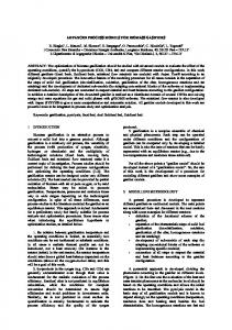
many of the leading commercial process simulators. Today the CAPE-OPEN Laboratories Network (CO-LaN, www.colan.org) is the internationally recognized, user-driven organization for the management, exploitation, and promotion of the CO standard. A recent review of industrial applications of the CO standard, including a brief discussion of the process/equipment co-simulation solution described here, can be found in Pons (2003). This paper describes the APECS integration framework for combining process simulation and CFD software using the CO interfaces. The application of APECS to process and fossil energy systems is also highlighted. APECS FEATURES AND CAPABILITIES The APECS integration framework uses the CAPE-OPEN (CO) software interfaces for unit operations, physical properties, and reaction kinetics. The methods of the CO unit operation interfaces enable the seamless use (e.g., Initialize, Edit, Calculate, Load, Save) of equipment models in the process flowsheet. The interfaces also facilitate the bi-directional exchange of stream information (flow rate, temperature, pressure, and compositions) between the process simulator and the equipment model. For CFD models, the multi-dimensional boundary conditions are mapped automatically to process streams and vice versa. The CO physical property interface is used to transfer constant or temperature-dependent physical properties (e.g., density, viscosity, heat capacity, thermal conductivity, molecular weight) from the process simulator to the equipment models. Similarly, the CO reaction kinetics interface facilitates the automatic transfer of reaction stoichiometry and power-law parameters from the process simulator to the equipment models. As shown in Figure 1, the hierarchy of unit operation/equipment models used by APECS ranges from high-fidelity CFD models to custom engineering models (CEMs) to fast reduced-order models (ROMs). The CFD models provide a detailed and accurate representation of a wide variety of process equipment items, while CEMs are typically engineering models that calculate mass and energy balances, phase and chemical equilibrium, and reaction kinetics. ROMs are a class of equipment models that are based on precomputed CFD solutions over a range of parameter values, but are much faster than CFD models. For example, the APECS system currently provides for automatically generating and using a ROM based on multiple linear regression to demonstrate the concept (Syamlal and Osawe, 2004). Future ROM solvers will include non-linear regression, neural networks (Osawe et al., 2006), and proper orthogonal decomposition. The APECS system drastically reduces the time and effort required to couple CFD-based equipment models into plant-wide simulations. Today, design engineers can use APECS to integrate CFD models into a process simulation in a matter of an hour or two using the CO software interfaces and easy-touse configuration wizards. The wizards are used
Aspen Plus Process Model
CFD Viewer
CO
Integration Controller (CAPE-OPEN Interface ) CO
CO
CO c
2-3D
≅
b r eP aR
FLUENT CFD
Custom Device Model
Nu Reduced Order Model
Configuration Wizard
Configuration Wizard
Configuration Wizard
Equipment Model Database
Figure 1. APECS Software Integration Framework
primarily to specify which equipment model parameters and stream ports to make available in the process simulator. Examples of common equipment parameters include the current and voltage for a fuel cell, or the impeller speed for a stirred tank reactor. Use of the CAPE-OPEN standard ensures that any equipment model can be linked to the COcompliant APECS framework. An easy-to-use template is provided for wrapping equipment models as CO-compliant models that can be executed in the APECS environment. The configured equipment models are stored in an equipment model database. After placing the detailed equipment model on the process flowsheet, a model selection GUI can be used to browse and select a suitable equipment model from the model database. Upon selection, the corresponding ports and parameters are automatically associated with the equipment model instantiated on the flowsheet. This then allows the process engineer to connect the appropriate number of input and output streams to the equipment model ports. The model edit GUI enables the process engineer to modify equipment parameters. The initial parameter values correspond to those set in the configuration wizard. The model edit GUI is also used to define a solution strategy consisting of a combination of one or more models/solvers ranging from fast ROMs to CEMs to rigorous CFD models. For example, one common solution strategy is to have the initial flowsheet iterations use a fast ROM and the final iterations use a high-fidelity CFD model. In this way, a process engineer can customize solution strategies from a hierarchy of models/solvers, thereby achieving the desired trade-off between speed and accuracy. If a parallel solver is available for a given equipment model, improved performance can be achieved by using multiple processors that may be executing on the same computer, or on different computers in a network. In the model edit GUI, an APECS user can specify the number of processors to be used, message passing protocol, and hosts file containing the list of computers on which to run the parallel job. The CAPE-OPEN COM/CORBA bridge implementation in APECS allows process simulations running under the Windows operating system to use equipment models running locally/remotely and serially/in parallel on Linux clusters and/or supercomputers (Zitney, 2004).
0 .6 8 240
SOFC current density (mA/cm2)
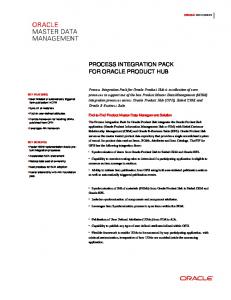
The APECS system also provides a wide variety of powerful analysis tools for optimizing overall plant performance (Zitney et al., 2006). Design specifications are used to calculate operating conditions or equipment parameters to meet specified performance targets. Case studies are used to run multiple simulations with varying input. Sensitivity analysis shows how process performance varies with changes to selected equipment specifications and operating conditions. Optimization is used for maximizing plant efficiency, energy production, and process economics. For process optimization in the face of uncertain variables — such as feed flow rates, or fluctuating prices of raw materials — and multiple and some time conflicting objectives, APECS offers stochastic modeling and multi-objective optimization capabilities (Figure 2) developed to comply with the CO software standard (Subramanyan and Diwekar, 2006).
0 .7 0
0 .7 0
220 0 .7 0
0 .6 8
0 .6 6
0 .7 0 0 .6 8
200
0 .7 0
0 .7 0 0 .7 0
180
0 .6 8 0 .7 0
0 .7 0 0 .7 0 160
0 .6 8 0 .6 6
0 .6 4
0 .6 8
0 .7 0
0 .6 2 0 .6 6 0 .6 2
0 .7 0 140
0 .6 0
0 .7 0 0 .7 0 0 .7 0
0 .6 4
120
0 .6 8 0 .6 6 0 .3 6 0 .6 0 0 .6 2 0 .6 4 0 .6 6 0 .6 8 0 .7 0
0 .3 8
0 .4 0
0 .4 2
0 .6 2 0 .4 4
C O 2 e m is s io n s (k g /k W h )
Figure 2. Multi-objective optimization tradeoff surface between CO2 emissions, fuel cell current density and efficiency for nextgeneration power plant
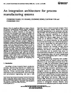
Advanced 2D and 3D visualization tools, including Paraview (www.paraview.org), available in APECS enable design engineers to display, within the process simulator, the results of a process/CFD cosimulation including contours of velocity, temperature, pressure, and species mass fractions for specified surfaces in the equipment models. Ongoing collaborative efforts aimed at integrating APECS with VE-Suite (www.vesuite.org), an open-source virtual engineering software toolkit, will enable users to explore co-simulation results in a context-based, user-centered interface including walking through a 3D representation of the power plant (Rubin, et al., 2006; Zitney, 2006, Bockelie et al., 2005). APECS POWER GENERATION APPLICATIONS At NETL, system analysts are applying APECS to a wide variety of advanced power generation systems, ranging from small fuel cell systems to commercial-scale power plants. Using APECS, the overall performance of solid oxide fuel cell (SOFC) auxiliary power units modeled using Aspen Plus® (Aspen Technology, 2004) are optimized with respect to the local fluid flow, heat and mass transfer, electrochemical reactions, current transport, and potential field in the SOFC simulated using detailed, three-dimensional, steady-state FLUENT® CFD models (Fluent Inc., 2004). The process/CFD cosimulations are performed over a range of fuel cell currents to generate a voltage-current curve and analyze the effect of current on fuel utilization, power density, and overall system efficiency (Zitney et al., 2004). In collaboration with cycle engineers at Alstom Power, APECS co-simulations have been developed for a conventional 30 MW pulverized coal-fired (PC) steam plant for municipal electricity generation and an advanced 250 MW, natural gas-fired, combined cycle (NGCC) power plant (Sloan et al., 2004, 2005). In the PC co-simulation, an Aspen Plus process design specification is used to adjust a FLUENT CFD model parameter for the boiler damper position (bypass resistance) to maintain a specified steam temperature over a range of loads, from the load at the maximum continuous rating to a control load, below which the boiler cannot sustain the required turbine inlet temperatures. For the NGCC cosimulation, an Aspen Plus process design specification is used to manipulate designated control parameters for the FLUENT CFD model of the heat recovery steam generator (HRSG) so that a specified superheat steam temperature is maintained for various load points over the range from 100% to 50% gas turbine load. Q
Volatile Feed Stream Coal Moisture Feed Stream Venturi Air Feed Stream SH Outlet Steam
P RO DUC TS
AI RIN W
W WP W AP
DCO UT
W
AIRP UM P
AIR -HX P -WA TER H2 OR ECY C
FC -A IR-A
FC -A IR FS PLIT
CAT-S EL
C-HTR
O 2 -S EP
CAT-D UP L
AIRS PL IT
PAI R
CO M B US T
CA T-O UTA
C-D EP L E T
CA T- O U T
F S P LI T
DU PL
H2 OP UM P CP3 CAT-I N-F
C HIL L O UT
CP 1
H2 OHX
E -O2
Throttle
Turbine Extractions
AN- O UT CA T-M UL T
CO L DPR OD
M ULT
C HIL L E R
CA T- R ED U W
Q
AN -S P L IT
CA T- I -F2
Boiler
M ULT
Tertiary Air Feed
AN- SE L W FP AN- RE DU H 2 OS P L IT
S ULF UR
W ATE R
Condenser Deaerator
AN- MUL T AN- IN -F 2
F C -HO L D M U LT
M ULT
Voltage (V)
F S P LI T
Fuel Utilization F UE L IN
Power D ensity (W/cm2)
AT R-A IR
AN- IN- F
F UE L P UMP
System Efficiency (LHV)
AN-ANH TR
P -FUE L IN
1.2
Secondary Air Feed
INTRE F
H 2 OD UM P AN- IN
R-FU E L
1
S TEA M
AN-IN-A
ANO DE IN 2
AN- O UT-A
DUP L
ATR
DE S ULF
AN1 - AN2 AN-DUP L
CFD Block
ANO D E
0.8
AN-RE CY C
Q ATR- CM B
0.6 0.4
Primary Air Feed
0.2
Air Preheater
Feedwater Heaters
0 0
5
10
15
20
C urrent (A)
Fuel Cell Auxiliary Power Unit (APU) with 3D CFD SOFC
GT GT Cooler Economizer HP Economizer OnceHP LP Through Evaporator Evaporator Separator FW
SH
Natural Gas
ALSTOM Conventional Steam Plant (250MWe) with 3D CFD Boiler
Economizers RH
Gas Turbine Air SH Outlet Steam
LP Pump
Condenser LP Turbine GT Exhaust Gas to HRSG IP Turbines
LP Drum HP Pump HP Turbine
ALSTOM NGCC (250MWe ) with 3D CFD HRSG
FutureGen Plant (250MWe) with 3D CFD Gasifier and 2D CFD Turbine Combustor
Figure 3. APECS Power Generation Applications
Research engineers at NETL are also developing APECS co-simulations to analyze potential FutureGen plant configurations (Zitney et al., 2006). In a recent demonstration case, the FutureGen co-simulation combined a plantwide Aspen Plus simulation with two FLUENT CFD-based equipment models, one for the entrained flow gasifier where fluid dynamics strongly affect synthesis gas quality and carbon conversion, and another for the gas turbine combustor where the blending of air and fuel is vital to gas turbine combustor performance and efficiency. Using APECS, Aspen Plus controls the cosimulation and automatically executes the gasifier and combustor CFD models as needed to converge the tail gas recycle loop and a design specification on the gas turbine inlet temperature. The design specification is met by manipulating the synthesis gas split between power production and hydrogen production. This co-simulation typically requires several hours of CPU time to converge on a singleCPU workstation. The turnaround time for the co-simulation is improved by running the computationally intensive CFD models in parallel on 2–8 CPUs of the Linux clusters at NETL and/or Pittsburgh Supercomputing Center. The co-simulation applications described above illustrate how APECS is helping NETL engineers optimize the coupled fluid flow, heat and mass transfer, and related phenomena that drive overall system performance. By combining process simulation and CFD software, together with advanced visualization and high-performance computing, APECS provides the high-fidelity solution and analysis capabilities required to achieve the aggressive integration, environmental, and performance goals for advanced power generation systems such as the DOE’s FutureGen plant. APECS R&D COLLABORATIONS NETL initiated APECS development in 2000 with a four-year cooperative R&D project with Fluent and its collaboration partners, AspenTech, Alstom Power, and West Virginia University. In March 2005, U.S. Secretary of Energy, Samuel Bodman, announced that Fluent and Reaction Engineering International were awarded $1.9M and $0.5M APECS projects, respectively, as part of a portfolio of $62.4 million for 32 clean coal research projects. The ongoing projects are focused on achieving the following APECS R&D objectives: • • • • •
Enhancement of APECS ease-of-use for configuring, managing, integrating, solving, and visualizing CFD-based equipment models within a CO-compliant process simulation environment. Demonstration of fast reduced-order models (ROMs) based on 2-3D CFD results. Integration of APECS power plant co-simulations to user-centered, interactive, hierarchical visualization environments at the immersive, 3D plant walkthrough level. Demonstration of a prototype dynamic APECS co-simulation capability for use in designing control strategies for advanced power plants. Development of a prototype parallel-modular solution approach in APECS for improving turnaround time for large-scale co-simulations involving the use of multiple high-fidelity, CFDbased equipment models.
Under the auspices of a U.S.-U.K. Memorandum of Understanding and Implementing Agreement (http://us-uk.fossil.energy.gov/) signed in November 2000, NETL is collaborating with the U.K.’s Virtual Plant Demonstration Model (VPDM) team, including Alstom Power U.K., Engineous Software, Fluent U.K., KS-Tech, ME Engineering, Mitsui Babcock, Process Systems Enterprise (PSE) Limited, RWE Innogy, and the University of Ulster. The main objective of the collaboration is to develop compatible, CAPE-OPEN standards-based software platforms for virtual power plant simulation for advanced fossil energy systems. The VPDM team is leveraging NETL’s APECS technology to integrate high-fidelity FLUENT CFD equipment models into overall power plant models developed with PSE’s gPROMS simulator (Williams, 2006). The APECS co-simulation tool will help the U.K. power generation and
associated industries to develop competitive power plant solutions and ultimately zero-emission technologies with significantly reduced development costs and technical risk. In the research community, NETL is working in close cooperation with Carnegie Mellon University on the development of CO-compliant reduced-order models based on CFD results; Iowa State University and Ames National Laboratory on coupling process/CFD co-simulation to immersive 3D virtual engineering software (Rubin, et al., 2006); Vishwamitra Research Institute on CO-compliant stochastic analysis and multi-objective optimization capabilities for process/CFD co-simulation (Subramanyan and Diwekar, 2006); and Reaction Engineering International on the development of CO-compliant power plant equipment models including a CAPE-OPEN interface to the GateCycle software, which is widely used in the power generation industry for process modeling (Swensen, 2006). SUMMARY This paper has highlighted NETL’s Advanced Process Engineering Co-Simulator (APECS) for coupling high-fidelity equipment models with process simulation for the design, analysis, and optimization of process engineering systems. The APECS integration framework and its capabilities have been described, including the use of the process-industry CAPE-OPEN (CO) software interfaces. Also highlighted was the application of the co-simulation technology to fossil-energy power generation systems including the coal-fired, gasification-based FutureGen power and hydrogen production plant. At NETL, the CO-compliant APECS process/CFD co-simulation technology is helping engineers to better understand and optimize the fluid dynamics and related phenomena that impact overall power plant performance. REFERENCES Aspen Technology, Aspen Plus 2004.1 User Guide, Cambridge, MA (2004). Bockelie, M.J., D.A. Swensen, C. Yang, M.K Denison, C.L. Senior, and A.F. Sarofim, “A Software Framework for Modeling Advanced Power Generation Systems,” In Proc. of the 30th International Technical Conference on Coal Utilization & Fuel Systems, April 16-21, Clearwater, Florida (2005). Braunschweig, B.L. and R. Gani, Software Architectures and Tools for Computer Aided Process Engineering, 1st ed., Elsevier Science, Amsterdam (2002). Fluent Incorporated, FLUENT User’s Guide, Lebanon, NH (2004). Osawe, M.O., “Fluent CAPE-OPEN COM/CORBA Bridge and CO-Compliant Unit Operation,” Proc. of the 2nd Annual U.S. CAPE-OPEN Meeting, May 25-26, Morgantown, WV (2005). Osawe, M.O., D.G. Sloan, W.A. Fiveland, and J. Madsen, “Fast Co-Simulation of Advanced Power Plants Using Neural Network Component Models,” In Proc. of the AIChE 2006 Annual Meeting, Paper 626b, Session: TD003 Cape-Open Numerical Components: Development and Usage, November 12-17, San Francisco, CA (2006). Pons, M., “Industrial implementations of the CAPE-OPEN standard,” Presented at the Sixth Italian Conference on Chemical and Process Engineering (IcheaP-6), June 8-11, Pisa, Italy (2003). Rubin, E.S., M. Berkenpas, K. Kietze, K.M. Bryden and D. McCorkle, “An Integrated Modeling Framework for Virtual Engineering of Advanced Power Systems with Near-Zero Emissions,” Proc. of the 31st International Technical Conference on Coal Utilization & Fuel Systems, May 21-25, Clearwater, FL (2006). Sloan, D.G., W.A. Fiveland, S.E. Zitney, and M. Syamlal, "Power Plant Simulations Using Process Analysis Software Linked to Advanced Modules," In Proc. of the 29th International Technical Conference on Coal Utilization & Fuel Systems, April 18-22, Clearwater, FL (2004). Sloan, D.G., W.A. Fiveland, M.O. Osawe, S.E. Zitney, and M. Syamlal, "Demonstrations of Coupled Cycle Analyses and CFD Simulations over a LAN," In Proc. of the 30th International Technical Conference on Coal Utilization & Fuel Systems, April 17-21, Clearwater, FL (2005).
Subramanyan K. and U. Diwekar, “Cape-Open Compliant Multi-Objective Optimization Capability for APECS Systems,” In Proc. of the AIChE 2006 Annual Meeting, Paper 626f, Session: TD003 CapeOpen Numerical Components: Development and Usage, November 12-17, San Francisco, CA (2006). Swensen, D.A., “Development of Cape-Open Unit Operations for Advanced Power Systems Modeling,” In Proc. of the AIChE 2006 Annual Meeting, Paper 535f, Session: TD001 Cape-Open Unit Operations: Development and Usage, November 12-17, San Francisco, CA (2006). Syamlal, M. and M.O. Osawe, “Reduced Order Models for CFD Models Integrated with Process Simulation,” Presented at the AIChE 2004 Annual Meeting, November 7-12, Austin, TX (2004). Syamlal, M., S.E. Zitney, and M.O. Osawe, “Using CAPE-OPEN Interfaces to Integrate Process Simulation and CFD,” CAPE-OPEN Update Newsletter, Volume 7, January (2004). Williams, T., “The gPROMS socket for local/remote CAPE-OPEN Unit and its application in the VPDM project,” CO-LaN 2006 Annual Meeting, March 9-10, Cannes, France (2006). Zitney, S.E., “High-Performance Process Simulation of Advanced Power Generation Systems,” Presented at SMART TechTrends 2004, August 3-6, Pittsburgh, PA (2004). Zitney, S.E., “Advanced Process Engineering Co-Simulation of the FutureGen Power and Hydrogen Production Plant,” Proc. of the AIChE 2005 Annual Meeting, October 30-November 4, Cincinnati, OH (2005a). Zitney, S.E., “CAPE-OPEN Integration for Advanced Process Engineering Co-Simulation,” Proc. of the 2nd Annual U.S. CAPE-OPEN Meeting, May 25-26, Morgantown, WV (2005b). Zitney, S.E., “Power Plant Virtual Engineering with Advanced Process Co-Simulation” Presented at Virtual Engineering 2006, May 2-3, Ames, IA (2006). Zitney, S.E., M.O. Osawe, L. Collins, E. Ferguson, D.G. Sloan, W.A. Fiveland, and J.M. Madsen, “Advanced Process Co-Simulation of the FutureGen Power Plant,” Proc. of the 31st International Technical Conference on Coal Utilization & Fuel Systems, May 21-25, Clearwater, FL (2006). Zitney, S.E., M.T. Prinkey, M. Shahnam, and W.A. Rogers, “Coupled CFD and Process Simulation of a Fuel Cell Auxiliary Power Unit,” Proc. of the ASME Second International Conference on Fuel Cell Science, Engineering, and Technology, Eds. R. Shah and S.G. Kandlikar, June 13-16, Rochester NY, Paper 2490, pp. 339-345 (2004).