Casting Process Planning Using Case Based Reasoning - CiteSeerX
Recommend Documents
Keywords: CAPP, generative methods, machining features, Geometrical Product .... Critical sequence generation based on datum references and manufacturing.
e-mail: [email protected]. 2Learning ... 3Intelligent Systems Program, University of Pittsburgh, Pittsburgh, PA 15260, USA; e-mail: ... these textual knowledge sources in an automated or semi-automated way for supporting problem-.
is used as a source of modi cation. In this paper, we present four systems that integrate generative and case-based planning: Prodigy/Analogy de- veloped at the ...
a player's current view of the field, as provided by the simula- tor league's ... We are currently integrating CBR into the Ohio Univer- sity RoboCats, a team that ...
School of Computer Science and IT, University of Nottingham, Nottingham, UK. .... Clinical Stage Gleason score PSA. Case 1. T2a. 7. 20.1. The second group of ...
from the numeric subroutines to web site generation. (Fernandez et ... ACAI selects a plan through simple matching of user's stated goal .... that ACAI contains only a few basic plans. ..... commence Website Builder for SMEs, in Proceedings of.
Therefore legal knowledge such as precedent cases and law rules must be accessible and relatively well structured, codified and indexed to enable AI research-.
knowledge-intensive case-based reasoning (CBR) method is adopted to ... components, and a conversational case-based reasoning (CCBR) technology is.
The case-based reasoning (CBR) approach could reuse this knowledge ... case-based reasoning for modeling infrastructure deterioration, was developed and ...
The computer integrated measurement .... For a very restricted class of tasks, the rule-based module is capable to suggest its own .... 2 (1998) 9-17. 2. Frakes ...
wich Campus, Old Royal Naval College, Park Row, Greenwich, London ... approach using case-based reasoning that indirectly measures an attacker's ... A typical cyber-attack involves a substantial number of steps, each one often being a cyber- ... hack
Abstractâ Case-based reasoning (CBR) is a methodology for solving problems. These problems may be of a variety of natures. In principle, no problem type is ...
2 Repair-based Optimization and Reinforcement Learning. 3. 2.1 Job-Shop Scheduling ... Practical optimization problems such as job-shop scheduling of- ten involve optimization ..... IEEE Computer Society Press, Los Alamos,. CA, 1990.
Case-based Reasoning for Diagnosis of Stress using. Enhanced Cosine and Fuzzy Similarity. Mobyen Uddin Ahmed, Shahina Begum, Peter Funk, Ning Xiong, ...
users in formulating queries for case retrieval. Existing ... a method for conducting conversation with automatically generated feature ... natural language text such as incident reports, legal briefs, and email ... potentially impractical for short-
oriented research on story understanding. Another root of current CBR ...... Case Retrieval Nets. Technical Report, Humboldt University. Berlin. 63. Burkhard, H.-D. (1998). ..... Lösung betrieblicher Entscheidungsprobleme. Doctoral Dissertation ...
Abstract. General Electric has created case-based reasoning systems for remote diagnostics, call center automation, and internal productivity projects.
Abstract. In case-based reasoning (CBR) a problem is solved by matching the problem description to a previously solved case, using the past solution in solving ...
(CBR) systems are identified and we use these goals to identify some limitations ... Throughout our lives, we experience explanations every day and they seem to ... Most people think of explanation as something identifying the cause for a par- .... t
Case-based reasoning (CBR) is a sub-field of Artificial Intelligence that deals with experience-based problem solving. CBR has its roots in .... case-base representations are a quite standard applications of AI .... tions in the petroleum industry.
modelling component, the Creator, for developing knowledge management .... based reuse of the workflow templates. ..... Email: [email protected]. Prof.
Whitney ~1989! suggest that, as part of the concurrent en- gineering process ..... ing are discussed in ~Dean & McDermott, 1987; Dean, 1989!. Most applications ...
the RoboCup simulation league in 1997, they noted that agent learning with CBR
... the next Robot Soccer World Cup in Padua, Italy, to be held in July, 2003.
Casting Process Planning Using Case Based Reasoning - CiteSeerX
has been implemented in a web-based virtual foundry environment using ... During past few decades companies have realized that in order to remain ... This led to development of computer aided design (CAD) and computer aided manufacturing ... process planning application in it. ..... Beyond 2000, Bangalore, (1999).
Transactions of the American Foundry Society, 111, 1321-1330, 2003
Casting Process Planning Using Case Based Reasoning R.G. Chougule Indian Institute of Technology, Bombay, India.
B. Ravi Indian Institute of Technology, Bombay, India. ABSTRACT We present an innovative approach to casting process planning based on case-based reasoning. Process planning involves deciding the methods, materials and machines for various steps in manufacturing. It is an important activity that affects product cost and quality, and requires experience. Such experience can be stored using a knowledge management system, then retrieved and modified for a new casting that is similar to a previous one (generative process planning). For entirely new castings, process plans are generated interactively by selecting the most appropriate options from a library, and become part of the case-base. A system has been developed to demonstrate both generative and variant process planning for castings, and has been implemented in a web-based virtual foundry environment using XML (eXtensible Markup Language). This will help in interaction between product designer, tooling engineer and foundry engineer at the early design stages enabling early prediction and prevention of manufacturing problems associated with the design. Key words: Casting, Case Based Reasoning, Knowledge Management, Process Planning, Virtual Foundry. INTRODUCTION During past few decades companies have realized that in order to remain competitive it has become necessary to introduce computer-aided systems. This led to development of computer aided design (CAD) and computer aided manufacturing (CAM). The introduction of these technologies greatly improved the quality of products and proved cost efficient. The link between these two technologies is a computer-aided process planning that has been a major research area in the last few years. The process planning translates design information into the process steps and instructions to efficiently and effectively manufacture products. Process planning encompasses the activities and functions to prepare a detailed set of plans and instructions to produce a part (Zhang et al, 1994). The process planning results into: • •
Routings that specify operations, operation sequences, work centers, tooling and fixtures. Detailed, step-by-step work instructions related to individual operations, operation parameters, and quality assurance checkpoints.
In the machining domain, the issue of computer aided process planning (CAPP) has been addressed by many researchers. Both generative and variant process planning approach have been widely employed using knowledge based systems, fuzzy logic, neural network, genetic algorithm, case based reasoning (Meziane et al, 2000). The generative approach involves automatic generation of process plan based on manufacturing information stored in the database, decision-making logic and algorithms. The variant process planning approach involves grouping the parts into family and storing standard process plan for each family, which is then retrieved depending on family of new part and then modified manually. Investigation in the machining sector shown that efficient CAPP systems could result in total reduction of manufacturing cost by up to 30%. The manufacturing cycle time and total engineering time could also be reduced by up to 50% (Younis 1997). However, in metal casting, process planning has been given a very little attention as compared to machining domain. Very little literature is available regarding the process planning of cast components. Out of the available literature most of the work is related to casting process selection that forms the first step for the process planning. In an earlier work, Sirilertworakul developed a knowledge base for alloy and process selection for casting (Sirilertworakul et al, 1993). Darwish developed an the preliminary casting process selection expert system (PCPSES) using Rule Master, a software package for developing expert systems (Darwish et al, 1996). Er developed a knowledge-based expert system for process selection for cast components (Er et al, 1996). Akarte used AHP for the casting process selection (Akarte et al, 1999), which was later extended to product-process-producer compatibility evaluation (Akarte, 2002a). In an earlier work related to process planning, Ajmel developed computer aided process planning and estimating system (Ajmel 1987). The system developed was interactive data base system in which data needs to be fed by the user.
Our work attempts to bridge the gap that exists in the metal casting domain. In this work, a computer-aided casting process planning system for cast components has been reported that helps design engineer in the process planning of the cast components at the design stage. Both generative and variant process-planning approaches have been demonstrated. PREVIOUS WORK The process planning system for the cast components has been implemented in a framework WebICE (Web-based Integrated Casing Engineering). This framework handles casing project information mainly related to product (Ravi, 2002). The current work deals with enriching the WebICE framework to handle foundry and process information and demonstrating the process planning application in it. As the work presented is extension of the WebICE, it is explained in brief in this section. The WebICE is a framework developed to capture casting information. It is developed in two tier client sever architecture. The server side components of the WebICE include project database template, library database, projects and functions. The project database template consists of default CDML tree and data blocks that can be automatically copied into a new folder while initiating a project. Each project is assigned a separate folder with a unique login and password. General functions have been developed for retrieving, displaying and updating data blocks; cloning and deleting a sibling block; displaying and copying library options; and linking, uploading and displaying images/models. To capture the information related to cast products, a Casting Data Markup Language (CDML) has been developed (Akarte, 2002b). It is based on XML (extensible Markup Language) – a meta-language to define domain-specific tags suitable for web-based databases. The CDML consists of two parts: CDML tree and data blocks. The CDML tree represents the hierarchical relationship between different types of information essential for collaboration between the product, tooling and foundry engineer, whereas the data blocks are used for storing the actual project data. The CDML tree has been created as a parent-child-grandchild structure for easy location of the desired information corresponding to each node and sub nodes therein. Each node in the tree has a specific name and an index number. CASTING PROCES PLANNING SYSTEM
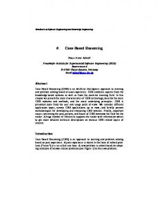
Fig. 1. Casting process planning
Product design is considered as an iterative process divided into preliminary design and the detailed design. At the preliminary stage, designers finalize different attributes like material, weight, overall size and a little bit tentative about surface finish, tolerances and dimensional parameters. While at the detailed design stage designer freezes all dimensional and quality parameters of the product. Similar to design, casting process planning can be divided into three levels viz: process selection, preliminary process planning and detailed process planning (also referred as methoding in foundry). The
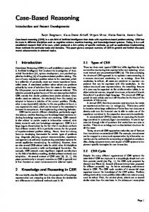
preliminary process planning is mainly concerned with decisions regarding the methods, steps and major process parameters (type of mold or core sand, pouring temperature, etc.). The detailed process planning involves determining all necessary process parameters, including detailed design of feeding and gating systems as shown in the fig 1. The work reported in this paper is focused on the preliminary process planning of the cast components. For preliminary casting process planning, both generative and variant process-planning approaches have been developed. The generative process planning approach involves automatically generating the process plan from the standard process plans stored in the libraries while variant process planning approach involves generating the process plan automatically. This overall methodology fro the casting process planning is shown in the fig. 2 and is explained in the next sections.
Fig. 2. Casting process planning methodology
For convenient handling of preliminary process planning information in the framework, it is divided hierarchically into activities, methods and steps. Different activities that are involved in the casting process are classified into: • • •
Pre-casting activities involving core sand preparation, core making, mold sand preparation and mold making Casting activities involving melting, holding and pouring Post-casting activities involving shakeout, cleaning and fettling
After fettling operation, casting is given to further processing viz. heat treatment and machining, if required and in-house facility is available. Otherwise, it is painted, packed and transported to the customer. These different activities are stored under PROCESS node of CDML tree. The casting process planning information is stored under the child nodes PRE_CASTING, CASTING and POST_CASTING, which in turn contain information regarding different activities in the sub-nodes; for example PRE_CASTING node stores the information about the pre-casting activities viz: CORE_SAND_PREP, CORE_MAKING, CORE_DRESSING, MOLDING_SAND_PREP and MOLD_MAKING. Each activity consists of different steps. These steps depend upon the method employed. For example, core making can be achieved by different methods like, oil sand method, hot-box
method, cold-box method and each method has different steps. This information is systematically stored in the library and can be easily browsed by clicking the corresponding node of the CDML tree and then library function associated with that node. Apart from different steps for performing each activity library provides a framework for handling data regarding the time and frequency for each step. VARIANT PROCESS PLANNING For the variant process planning, a virtual foundry environment has been created. The virtual foundry is mainly concerned with information modeling in which information related to manufacturing resources and manufacturing processes has been modeled. The manufacturing resources are machines and tools that are used to cast a product. The manufacturing resource model capture the static information i.e. machine specifications and operating parameters of the machine. The information regarding the manufacturing resources is captured under the node EQUIPMNET which in turn has different sub nodes viz: SAND_PREP, CORE_PREP, MOLDING, MELTING, POURING, TREATMENT, MACHINIG, TESTING and OTHERS to capture corresponding equipment information. A typical virtual foundry layout is shown in fig 3.
Fig. 3. Virtual foundry layout.
The variant process planning involves generating the process plans from the standard process-planning library corresponding to each activity in the PROCESS node of CDML tree. The user can browse through it by clicking the function View_Options and the data from the library can be copied to data block associated with corresponding node (activity) by function Copy_Options while performing the process planning interactively as shown in fig. 4. The variant process planning facility is used initially when enough cases are not available for generating the process plan automatically using generative process planning approach. GENERATIVE PROCESS PLANNING Generative process planning involves generating the process plan automatically. For this purpose, case based reasoning methodology, using nearest neighbor algorithm and analytical hierarchy process has been employed. CASE BASED REASONING A case based reasoning (CBR) methodology reuses the previous experience to generate new solutions. It involves retrieving the old solutions (cases) that match the new case from input design description. The best matching candidate is then chosen and adapted to fit new design description and verified for consistency to form new solution. Case based reasoning involve number of benefits like finding the solutions to complex problems more quickly, transferring experience from skilled specialist, discovering decision knowledge in hidden data. The case based reasoning cycle consists of four steps viz: determining features, case retrieval, case adaptation and retaining case •
Determine features: It involves finding features that can describe new problem completely and correctly.
• • •
Case retrieval: Retrieve one or several similar cases from case-base. Case retrieval requires a combination of search and matching. Case adaptation: Recognize the differences between the selected case (cases) and new problem, and adapt the selected case to solve the new problem. Retaining case: The adapted case is retained in the case base for further use.
One of the biggest issues in case based reasoning is the retrieval of appropriate case. In practice popular retrieval algorithm are nearest neighbor algorithm, inductive indexing and knowledge based indexing. In our work nearest neighbor algorithm has been used for the retrieval purpose as it gives good results if the cases in the case-base are few and matching conditions are well defined. It involves specifying values for the attributes for new castings along with the weight corresponding to attribute. For evaluating the weights of the attributes analytical hierarchical process has been employed.
(a)
(b)
Fig. 4. a) Partial CDML tress showing sub nodes under process node b) A typical library
ANALYTICAL HIERARCHY PROCESS Analytical hierarchy process (AHP) involves grouping the attributes depending upon their similarity and comparing them pair-wise. The AHP includes following steps: Develop hierarchical structure of decision problem in terms of overall objective, criteria, sub criteria and decision alternatives • Determine, on pair wise basis, the relative priorities of the criteria and sub criteria that express their importance in relation to element at higher level. • Calculate the weights based relative priorities of criteria and sub criteria. The details of AHP calculations are given in annexure 1 •
CASE RETRIEVAL Case retrieval can be split into two distinct phases viz: a) Screening the process database (process library) for material and process compatibility and b) Identifying the nearest neighbor from the screened cases. Screening Process Data Base and Case Base This involves screening the process library for identifying the feasible processes for the problem (new project) by comparing the attribute values with compatibility data of different processes stored in the library. The attributes considered for this purpose involve casting weight, casting size, minimum core hole diameter, minimum section thickness and delivery quantity. The casting process covered in this database involve green sand casting, high pressure sand casting, shell molding, no bake process, gravity die casting, low pressure die casting, high pressure die casting, wax investment process, foam investment process. The materials that are considered for building the process libraries involve gray iron, ductile iron, alloy iron, steel,
alloy steel, aluminum, copper, magnesium and zinc. For screening the feasible process, material specific database has been prepared for different casting processes. A sample library structure for grey iron with green sand molding process is shown in the annexure 2. Then only those cases (old projects) for which feasible processes have been matched are considered for retrieval. The attributes, which have been identified for the retrieval of case, include: casting material, maximum casting length, casting weight, minimum section thickness, maximum section thickness, core hole diameter, shape complexity, surface roughness, maximum void size, tolerance, order quantity, production rate, sample lead time and production lead time. Determining the Nearest Neighbor For specifying the weights using AHP the attributes (except material) are divided into geometry related attributes, quality related attributes and production related attributes as given below. • • •
Geometry related attributes such as maximum casting length, casting weight, minimum and maximum wall thickness, core hole diameter, shape complexity Quality related attributes such as surface roughness, tolerance and maximum void size Production related attributes such as order quantity, production rate , sample lead time, production lead time.
For subjective attribute, like shape complexity which is expressed in LOW, MEDIUM, HIGH, attribute value needs to be defined. Rating method has been used to quantify the shape complexity. Rating is the intensity of a qualitative criterion to differentiate the alternatives. The quantification of intensities belonging to each criterion has been done using the analytical hierarchy process (AHP) methodology. These quantitative rating values have been used as attribute values to calculate similarity coefficient. The ‘Calculate_Rating’ function has been linked to the respective node in CDML tree, which can be reached by expanding the node PROJECT.PRODUCT.RATINGS. Based on the attribute values and weights specified, a similarity coefficient for the problem (new project) is determined. Similarly, similarity coefficients have been determined for each casting project in the case base (previous cases) using weights specified and corresponding attribute value of the project. Based on these similarity coefficients, the nearest three cases have been identified. In addition, similarity indices have been determined to express similarity by normalizing similarity coefficients of previous cases to the similarity coefficient of new problem on the scale 0 to 1 in which 1 indicates the best match. n
SC = ∑ Ai × wi
(Equation 1)
SI = SC P SC N ………………………………………….. for SCP / SCN ≤ 1
(Equation 2)
i =1
(
)
SI = 1 − SC p − SC N SC N …………………………… for SCP / SCN > 1 Where, SC – Similarity coefficient SCP - Similarity coefficient of previous case A - Attributes n - Number of attributes
SI- Similarity index SCN - Similarity coefficient of new project (problem) w - Importance weighing of attribute i i - Individual attribute from 1 to n
In addition, to improve the accuracy for the nearest neighbor algorithm functions have been pre-defined for some attributes for retrieval purpose. For example for retrieval purpose size of casting (in hundreds) and quantity of manufacturing (may in thousand) may be the influencing parameter in determining the value of similarity index as compared to tolerance (having values in few microns) that have less effect on the value of similarity coefficient but plays very important role in process planning. To deal with such a problem the functions have been defined for the individual parameter. These functions eliminate non-matching cases based on individual attributes. A typical result of case based reasoning algorithm is shown in the fig 5.
Fig. 5. Result of CBR ( first three nearest neighbor)
Once the case or cases that are to be used for deriving the solutions are known, the next step is to adapt the solution from the selected case to the problem at hand. If the current problem is nearly same as that which has already been solved, then old solution can be used directly and no adaptation is needed. However, if it is not the case, then the solution can be adapted by some local adjustment. In the absence of suitable case in the case-base, process plans will be generated by variant process planning approach. A partial process plan is shown in fig 6.
Fig. 6. Partial process plan
After case adaptation and modification, the new case is retained which forms a part of case-base for future reference. APPLICATIONS The current manufacturing environment in the foundries is rapidly changing because of changing market conditions and international competition. For survival, it is imperative to produce products at low cost and still meeting the quality requirements. In addition, product design and development with shorter lead-time is becoming critical. The pressure from regulatory bodies in terms of energy conservation, environmental protection and operational safety still worsen the situation. Some of these challenges can be met by application of new technologies and approaches like concurrent engineering, integrated product process development, collaborative engineering etc. to the metal casting industries. It has been well
known that a large percentage of product cost is committed once its features, material, tolerance and surface quality characteristics have been selected at the design stage. Almost, 70-80 % of the product life cycle cost is determined during design phase, whereas designing itself accounts for only 6 % of the product cost. When design of product is in its preliminary stage cost involved in design change is less but it has maximum influence on the product cost. Unfortunately, metal casting domain often involves late design changes after casting is given to manufacturing resulting in the increased cost and time. This is because, it is unlikely that casting product designer will have all the knowledge needed to solve a whole range of casting design problems. On the other hand, casting experts often using knowledge obtained through extensive experience can assess a casting design and its suitability for casting process in a relatively short time. So in practice it is essential that casting product designers need to communicate with casting experts. As the complete process planning system is developed on the web it is possible to work product and process engineer simultaneously on the given casting project achieving the concurrent product process development of the cast component. This enables a two-way interaction between the process planning and product design. Secondly, it is becoming essential to feedback the information from process planning to assist designer at early stages in assessing various design features. However, the manufacturing knowledge is not readily available or captured within the design stage, which constrains designers to make critical decisions without exploring alternative strategies. If the designer realizes early enough that some of the features require expensive tooling or demands special tools or expensive process, it would be possible to try another alternative that is more cost effective. CONCLUSIONS AND FUTURE SCOPE Computer aided process planning has been a focal point of research in both scientific and industrial world. However, in the casing domain area of process planning is neglected. This paper presents work on preliminary process planning of the cast components at the design stages pointing towards the integrated product process development. Case based reasoning methodology has been used for process planning. This integrated product process design environment has been implemented on the Internet so that team members comprising of design engineer, foundry engineer and tooling engineer can participate in the product development and thus problems related to manufacturing and tooling can be assessed at the early design stages thus leading to considerable reduction in casting development cost and time. We hope that computer aided casting process planning system will be a promising technology for long-term research and the promotion of computer aided foundry engineering (CAF-X) like CA-X in machining domain. The present work can be extended for the detailed process planning involving gating and feeding design for the product. It is also possible to perform solidification simulation for the particular cast products thus different defects associated with the casting can be analyzed at the design stage giving valuable feedback to the designer to design a defect free casting. ACKNOWLEDGEMENT Authors wish to acknowledge Mr. M. M. Akarte, doctorate student of IIT Bombay, for assistance in developing the system. REFERENCES Ajmel, A., “The Development of a Computer-Aided Process Planning and Estimating System for Use in a Jobbing Foundry”, Recent Developments in Production Research. Collection of Refereed Papers Presented at the IXth International Conference on Production Research, pp.589-597, (1987). Akarte M., M.“A Framework for Web-Based Integrated Casting Engineering and Its Application to Product-ProcessProducer Compatibility Evaluation,” Ph.D.Thesis, IIT Bombay, (2002a). Akarte M.M., Ravi B., Casting Data Markup Language for web-based collaborative engineering, Transactions of the AFS, 2002, Vol.112 (2002b). Akarte M.M., Ravi B., Creese R, “Casting Process Selection Using AHP and Fuzzy Logic,” Int. Seminar on Mfg. Tech. Beyond 2000, Bangalore, (1999). Darwish S.M., El-Tamimi A.M., “The Selection of Casting Process Using an Expert System,” Computers in Industry, Vol. 30, pp.77-86, (1996). Er A., Sweeney E.T, Kondic, “A Knowledge Based System for Casting Process Selection,” AFS Casting Congress, Philadelphia, April 1996, pp. 20-23 (1996). Meziane F., Vadera S., Kobbacy K, Proudlove N, “Intelligent Systems in manufacturing: Current Developments and Future Prospects”, Integrated Manufacturing Systems, Vol. 11, n4, pp. 218-238, (2000) Ravi B, Akarte M. “Web-based Collaborative Engineering of Cast Products”, 30 th Computers and Industrial Engineering Conference, Greece June 29 – July 2, 2002. Saaty TL, “How to Make Decision: The Analytic Hierarchy Process,” Interfaces, Vol. 24, n6, pp. 19-43, (1994).
Sirilertworakul N., Webster P., Dean T., “ A Knowledge Base for Alloy and Process Selection for Casting,” International Journal of Machine Tools Manufacturing, Vol.33, No.3, pp.401-415 (1993). Younis M.A., Waheb M.A., “A CAPP System for the Rotational Component”, Computers and Industrial Engineering, Vol. 33, pp. 509-512, (1997). *Zhang H., Alting L., “ Computerized Manufacturing Process Planning Systems”, Chapman & Hall, (1994).
ANNEXURE 1 The various steps to find the vector of weights and check the consistency of judgment, as suggested by Satty are as follows: 1) Construct a pair-wise comparison matrix: Assuming n criteria, the pair-wise comparison of criterion i with criterion j yields a square matrix of criteria called A1nxn. Where, aij is the element in the pair-wise comparison matrix, giving comparative importance of criterion i with respect to criterion j. In matrix A1, aij = 1, when i = j and aji = 1/ aij .
A1n×n
⎡ a11 ⎢a = ⎢ 21 ⎢..... ⎢ ⎣a n1
........... a1n ⎤ a 22 ........... a 2 n ⎥⎥ ..... ........... ..... ⎥ ⎥ a n 2 ........... a nn ⎦ a12
2) Find weight of each criterion (Wj) by calculating geometric mean of ith row (GMi) and then obtain the relative weights of each criterion by normalizing geometric means of rows in the comparative matrix.
⎡ ⎤ GM = ∏ aij ⎢ ⎥ ⎣ j =1 ⎦ n
1
i
3)
n
and
Wi = GM i
n
∑ GM i =1
i
Calculate matrix A3 and A4, such that A3 = A1 × A2 and A4 = A3 A2 , Where, A2 =
[w1
w2 .......... wn ]
T
4) Find out the maximum eigen value (λmax), which is the average of matrix A4. 5) Calculate consistency index (CI ) = (λ max − 1) ( n − 1) 6)
Obtain the random index (RI) from, for the number of criteria used in decision-making from table 1. Table 1. Random Index for Matrix (Satty, 1994)
Order of Matrix Random Index (RI)
1
2
3
4
5
6
7
8
9
10
0.00
0.00
0.58
0.90
1.12
1.24
1.32
1.41
1.45
1.49
7) Finally, calculate the consistency ratio (CR ) = CI RI . Usually, a CR of 0.10 or less is considered acceptable. ANNEXURE 2 1.1.0 ADMIN.FOUNDRY.CAPABILITY CD110_LIB-142.XML CD142.XML 2001.07.07