Jun 26, 2006 - Pole-face-windings And Figure-of-eight Loop Powering. The working point of the CERN Proton Synchrotron, which is equipped with combined ...
EUROPEAN ORGANIZATION FOR NUCLEAR RESEARCH CERN - AB Department CERN-AB-2006-065
Cern Proton Synchrotron Working Point Control Using An Improved Version Of The Pole-face-windings And Figure-of-eight Loop Powering J.-P. Burnet, M. Giovannozzi, E. Métral, O. Michels, R. Steerenberg, B. Vandorpe CERN, Geneva, Switzerland
Abstract The working point of the CERN Proton Synchrotron, which is equipped with combined function magnets, is controlled using pole-face-windings. Each main magnet consists of one focusing and one de-focusing half-unit on which four pole-face-winding plates are mounted containing two separate coils each, called narrow and wide. At present they are connected in series, but can be powered independently. In addition, a winding called the figure-of-eight loop, contours the pole faces and crosses between the two half units, generating opposite fields in each half-unit. The four optical parameters, horizontal and vertical tune and chromaticity, are adjusted by acting on the pole-face-winding currents in both half units and in the figure-of-eight loop, leaving one physical quantity free. The power supply consolidation project opened the opportunity to use five independent power supplies, to adjust the four parameters plus an additional degree of freedom. This paper presents the results of the measurements that have been made in the five-current mode together with the influence of the magnetic nonlinearities, due to the unbalance in the narrow and wide winding currents, on the beam dynamics.
Presented at EPAC'06, Edinburgh, UK, June 26-30, 2006 Geneva, Switzerland June 2006
CERN PROTON SYNCHROTRON WORKING POINT CONTROL USING AN IMPROVED VERSION OF THE POLE-FACE-WINDINGS AND FIGURE-OF-EIGHT LOOP POWERING J.-P. Burnet, M. Giovannozzi, E. Métral, O. Michels, R. Steerenberg, B. Vandorpe, CERN, Geneva, Switzerland Abstract The working point of the CERN Proton Synchrotron, which is equipped with combined function magnets, is controlled using pole-face-windings. Each main magnet consists of one focusing and one de-focusing half-unit on which four pole-face-winding plates are mounted containing two separate coils each, called narrow and wide. At present they are connected in series, but can be powered independently. In addition, a winding called the figure-of-eight loop, contours the pole faces and crosses between the two half units, generating opposite fields in each half-unit. The four optical parameters, horizontal and vertical tune and chromaticity, are adjusted by acting on the pole-face-winding currents in both half units and in the figure-of-eight loop, leaving one physical quantity free. The power supply consolidation project opened the opportunity to use five independent power supplies, to adjust the four parameters plus an additional degree of freedom. This paper presents the results of the measurements that have been made in the five-current mode together with the influence of the magnetic nonlinearities, due to the unbalance in the narrow and wide winding currents, on the beam dynamics.
One power converter to power the narrow and wide focussing windings in one half of the main magnet, one to power the narrow and wide de-focussing windings in the other half of the main magnet and a third power converter to power the figure-of-eight loop that contours both poles of the main magnet. Each operational power converter has its dedicated spare, which means that there are in total six power converters available. This configuration precluded specific working point that was required for the novel Multi Turn Extraction studies [1], which was one of the reasons that led to study the improved powering scheme.
MAIN MAGNET AND POLE FACE WINDINGS The pole-face-windings (PFW’s) and the figure-ofeight loop are mounted inside the main magnets in order to control the working point during the acceleration cycle. At present they are powered by three power converters.
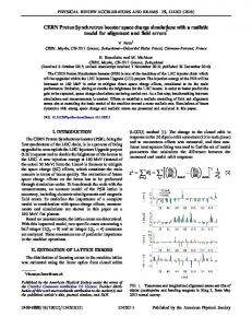
Figure 1: Reference main magnet unit with the PFW’s on the poles and the figure-of-eight loop contouring the poles.
Figure 2: 3-CM and 5-CM schematics for the focussing circuits. The cabling between the power converters, patch panel and the PFW’s is designed such that it is possible to switch semi-automatically between different configurations, by means of a locally controlled electromechanic patch panel. However, only one configuration, the 3-current mode (3-CM) [2], is used for beam operation until now. Figure 2 illustrates the connections for the PFW-F circuit in 3-CM at the left and 5-current mode (5-CM) [3] on the right, separating the narrow and wide circuits. The parallel branches in both schematics represent the PFW’s in the odd (FWI) and even (FWP) main magnet units. The PFW-D circuit is connected in exactly the same way as the PFW-F, while the figure-of-eight-loop powering remains unchanged. The control for the five power converters was also modified in order to be able to execute five independent reference functions.
14 GeV/c measurements
Regulation problems When the main magnetic field is ramped it induces a voltage in the PFW’s, which alters the final currents in the various circuits. In the 3-CM these currents partly cancelout as they have opposite polarity for the wide and narrow windings. However, in the 5-CM they are sufficiently important, especially for the wide circuit, that the present regulation cannot correct for it, as the induced currents on the injection plateau rises to -40A for the focussing wide circuit and +15A for the focussing narrow circuit (Fig. 3). Slightly lower currents were observed for the defocussing circuits.
100 80
0.25
0.2
0.2 2
4000
Under- and overshoot due to induced voltage (Bdot) Coupling matrices for the 5-CM are not identical to the 3-CM
Injection
2
R = 0.9975
3000
0 350
400
450
500
550
600
2000
650
0.15 -0.02
-0.015
-0.01
-0.005
0
0.005
0.01
0.015
0.15 0.02
dp/p
Figure 5: 3-CM and 5-CM working point comparison with figure-of-eight loop reduced by 30 A at 14 GeV/c.
-20 1000
-40 -60
0
Time [ms]
Figure 3: 3-CM and 5-CM currents for the focussing circuit using the present regulation. The regulation was temporarily modified, for the machine development sessions, in order to reject the induced voltage by adding the Bdot signal, which is the image of the induced voltage, to the regulation. Figure 4 shows the reduction of the induced currents for the PFWF circuit. A reduction to about ± 5A for the focussing and approximately ± 1A for the de-focussing circuit were realized. The remaining induced currents were acquired and subtracted from the current functions calculated by the working point application and were therefore not seen by the beam. 140
8000 FN power supply (5-CM) FW power supply (5-CM) PR.GSMDWFN F power supply (3-CM) PR.SCBFC
120 100 80 60
7000 6000 5000 4000
Injection
40
3000
Reduced under- and overshoot
20
2000
0
1000 100
150
200
250
300
350
400
450
-20
500
550
600
B [Gauss]
PFW-F power supply current [A]
0.3
y = 0.9267x + 5.3961x + 0.2449
20
300
0.35
2
6000
40
250
0.3
2
R = 0.9978
Qy 3-CM 2 y = -146.29x + 4.2123x + 0.3 Qy 5-CM R 2 = 0.9982 Poly. (Qy 5-CM) Poly. (Qx 5-CM) Poly. (Qy 3-CM) Poly. (Qx 3-CM)
R = 0.9971
7000
5000
200
0.35
2
y = -7.5042x + 4.3547x + 0.2891
y = 135.44x + 5.6081x + 0.239
B-field
150
0.4 Qx 5-CM Qx 3-CM
2
60
100
0.4
0.25
8000
FN power supply (5-CM) FW power supply (5-CM) PFW-FN ref. F power supply (3-CM)
120
B [Gauss]
PFW-F power supply current [A]
140
The obtained 14 GeV/c matrix was used to measure the influence of unbalancing the currents in the narrow and wide windings, by keeping the working point similar. Therefore a standard 3-CM working point was transformed to the same 5-CM working point, by programming the same currents in the wide and narrow windings of each focussing and defocusing circuit. In order to change the balance between the narrow and wide windings, the current of the figure-of-eight loop was then reduced by 30 A from 636 A to 606 A and the initial working point was re-calculated using the measured matrix, by varying only the four currents of the PFW-F and PFW-D narrow and wide windings.
Qy
The beam based measurements were started by verifying the regulation followed by measuring the 5-CM matrices at 14 GeV/c and 26 GeV/c which relate the five individual PFW and figure-of-eight loop currents: IFN, IFW, IDN, IDW, I8L with the 4 working point parameters: Qh, Qv, ξh, ξv.
Qx
3-CM AND 5-CM MEASUREMENTS
650 0
Time [ms]
Figure 4: 3-CM and 5-CM currents for the focussing circuit using the modified regulation
The results of the non-linear chromaticity measurements for the initial and final currents are plotted in Fig. 5, where the initial working point shows a very linear behaviour over a nearly 3% range of dp/p. After the reduction of the figure-of-eight loop current and the recalculation of the working point the non-linearities were enhanced slightly, but did not cause any beam blow up or losses. Table 1 shows the numerical values for the required and measured working point and the final currents that were applied to the different windings. The errors between the required and measured values confirm that the matrix is correct. Table 1: Numerical values for the 5-CM working point with figure-of-eight loop reduced by 30 A at 14 GeV/c. Comparison between initial and final measured working point Qh ξh Qv ξv 0.2361 0.880021 0.2995 0.65629 required 0.239 0.898878 0.3 0.668619 measured 0.0029 0.018857 0.0005 0.012329 error Measured PFW power supply currents [A] IFN IFW IDN IDW I8L 101.32 109.98 -123.35 -111.34 606.50
26 GeV/c measurements The same measurements were repeated on a 26 GeV/c cycle, where the main magnets are in saturation. Figure 6 compares the 3-CM working point with the 5-CM working point for which the figure-of-eight loop current was reduced by 300 A from 1535 A to 1235 A. Unfortunately there is not enough data available in the 3CM at this moment to make a full comparison between
0.31
4
3
0.29
2
y = -6E+06x - 10487x - 30.247x + 0.6313x + 0.2823 2 R = 0.9592
0.29
4
3
2
y = 489049x + 6624.5x - 105.43x - 0.1481x + 0.2798
0.31
0.29
2
R = 0.956
0.28
0.29
0.27
0.25 0.23
4
3
2
y = 611334x + 7676.8x - 235.99x - 0.3371x + 0.2827 2 R = 0.9847 4 3 2 y = -1E+06x - 13956x + 9.7995x + 2.035x + 0.2197 2
R = 0.9613
0.26 0.25
Qy
0.27
0.24
0.21
0.23
0.19
4
3
2
y = -1E+06x - 6906x - 131.92x + 1.9444x + 0.2212
0.22
2
R = 0.9734
0.17 0.15 -0.015
-0.01
-0.005
0
0.005
0.21 0.01
0.2 0.015
dp/p Qx (I8L -300A)
Qx (I8L -100A)
Qy (I8L -300A)
Qy (I8L -100A) Poly. (Qx (I8L -300A))
Poly. (Qy (I8L -300A)) Poly. (Qx (I8L -100A))
Poly. (Qy (I8L -100A))
Figure 7: 5-CM working point comparison with figure-ofeight loop reduced by 100 A and 300 A at 26 GeV/c.
0.28
0.27 0.27 4
3
2
y = 611334x + 7676.8x - 235.99x - 0.3371x + 0.2827 2 R = 0.9847
0.23
0.26
0.21 4
3
2
y = -1E+07x + 21177x - 117.27x + 1.4344x + 0.2179 2 R = 0.9618 4 3 2 y = -1E+06x - 13956x + 9.7995x + 2.035x + 0.2197 2 R = 0.9613
0.19 0.17 0.15 -0.015
-0.01
-0.005
0
0.005
0.01
Qy
0.25
Qx
0.3
0.33
Qx
the 3-CM and 5-CM. The green and purple data points clearly indicate the presence of non-linearities for the 5CM working point, but no beam blow-up or losses were observed. The numerical values are given in Table 2 where the errors between the required and measured values show that there is a considerable difference for the vertical chromaticity that after more detailed analysis turned out to be due to wrong matrix coefficients relating the currents in the PFW-F windings and the vertical chromaticity. Unfortunately no additional measurements could be made as the CERN PS was shut down in 2005 and has just restarted.
0.25 0.24 0.23 0.015
dp/p Qx 5-CM Poly. (Qy 5-CM)
Qx 3-CM Poly. (Qx 5-CM)
Qy 3-CM Poly. (Qy 3-CM)
Qy 5-CM Poly. (Qx 3-CM)
Figure 6: 3-CM and 5-CM working point comparison with figure-of-eight loop reduced by 300 A at 26GeV/c. Table 2: Numerical values for the 5-CM working point with figure-of-eight loop reduced by 300 A at 26 GeV/c. Comparison between initial and final measured working point Qh ξh Qv ξv 0.2179 0.230689 0.2823 0.100489 required 0.2197 0.327186 0.2827 -0.05366 measured -0.0018 -0.096497 0.0004 error 0.15414 Measured PFW power supply currents [A] IFN IFW IDN IDW I8L 405.54 380.89 179.73 208.19 1235.75
Figure 7 compares the two 5-CM working points for two different reductions on the figure-of-eight loop current: -100 A and -300 A. As the current in the figureof-eight loop is decreased from -100 A to -300 A the currents in the PFW-F and PFW-D circuits need to be increased by nearly a factor of 2, in order to maintain the same working point. The non-linearities, which depend mainly on the difference between the narrow and wide winding currents, are nevertheless enhanced slightly from one case to the other, but have no real effect on the beam. Table 3: Numerical values for the 5-CM working point with figure-of-eight loop reduced by 100 A at 26 GeV/c. Comparison between initial and final measured working point Qh ξh Qv ξv 0.2179 0.230689 0.2823 0.100489 required 0.2212 0.312544 0.2798 -0.02358 measured -0.0033 -0.08186 0.0025 error 0.124069 Measured PFW power supply currents [A] IFN IFW IDN IDW I8L 205.33 201.93 86.91 88.74 1435.20
CONCLUSION AND PLANNING From the beam based measurements it can be concluded that the 5-CM can be used, gives more freedom in working point adjustments and that the enhanced nonlinearities that were observed do not influence the beam performance negatively. The project to renovate the power converters [4] and to implement the 5-CM at the same time has been approved and will be executed over the next two years. The mile stones are as following: • 2004: beam based measurements were made in order to study the feasibility and the effect of unbalancing the wide and narrow windings on the magnetic nonlinearities. • 2005 and beginning 2006: development and construction of the new power converters. • End 2006 and 2007: installation and tests of the proto-type power converter. After final validation of the proto-type the remaining power converters will be installed. The 5-CM matrices for the different energies will be measured and a smooth transition to the 5-current mode can be made during the run, followed by beam based studies in the 5-CM in parallel with physics operation. • 2008: start-up in 5-current mode and continue studies to explore the behaviour of the non-linearities as a function of the PFW currents.
REFERENCES [1] M. Giovannozzi et al, these proceedings [2] P. Lefèvre and R. Gouiran, “Projet de Nouveaux enroulements Polaires Pour le CPS” MPS/DL/Note 74-11, June 1974. [3] R. Gouiran, “Projet d’un Nouveau Systeme d’Enroulements polaires a Cinq Courants”, MPS/SM/Note 75-21, 13 August 1975. [4] J.-P. Burnet and O. Michels, “Projet de Consolidation des Convertiseurs PFW” Note Technique AB-PO Nº10, EDMS: 585302, April 2005.