Purdue University
Purdue e-Pubs International Compressor Engineering Conference
School of Mechanical Engineering
1994
CFD Simulation of the Flow Through Reciprocating Compressor Self-Acting Valves P. Cyklis Cracow University of Technology
Follow this and additional works at: http://docs.lib.purdue.edu/icec Cyklis, P., "CFD Simulation of the Flow Through Reciprocating Compressor Self-Acting Valves" (1994). International Compressor Engineering Conference. Paper 1016. http://docs.lib.purdue.edu/icec/1016
This document has been made available through Purdue e-Pubs, a service of the Purdue University Libraries. Please contact
[email protected] for additional information. Complete proceedings may be acquired in print and on CD-ROM directly from the Ray W. Herrick Laboratories at https://engineering.purdue.edu/ Herrick/Events/orderlit.html
CFD SIMU LATIO N OF THE FLOW THRO UGH RECIP ROCA TING COMP RESSO R SELF-ACTI NG VALV ES Piotr Cyklis, Cracow University of Technology, Poland
ABST RACT In the paper the suitability of CFD method for the reciprocating compressor valve flow analysis has been investigated. The simulation has been worked up for the suction valve of the 4XD58 Polish compressor. It has been shown that the CFD simulation is fast and reliable tool for valve design. It has been shown that use of small workstation or PC computer gives results which are comparable with those of the experimental measurements. The basic valve geometry has been improved on the basis of the stream function contours. For the improved geometry the mass flow rate for the same pressure drop across the valve channel has been calcula ted.
1. INTRO DUCT ION In the new generations of air, refrigerating and gas reciprocating compressors there is a tendency towards smaller dimensions and considerable rotational speed. This makes it necessary to investigate more closely the phenomena that so far have most commonly been described as geometrically one-dimensional, by means of various types of factors. These phenomena include the heat exchange processes in the compre ssor, flow and pressure oscillations in the system and head, and first of all flow throttling in the valve channels. High rotational speed shortens the valve opening time, so a given volume of medium must flow through the valve in much shorter time than in case of slow-running compressors. There are two ways of achieving this: to intensifY the pressure difference on the valve or reduce the throttling. Intensification of pressure difference leads to the increase of compre ssor power demand. In tum, the valve throttling can be achieved by either enlarging the valve gap cross-s ection or increasing the valve flow coefficient a. The latter one is more favorable because it does not cause the growth of the working plates mass. The aim of this paper was to find out the suitability of CFD (Comp utational Fluid Dynamics) methods in the analysis of flow throttling in the reciprocating compressor self-ac ting valve. There are several leading programs of this type known at present, such as: PHOENICS, FLOW 3D, FLUEN T, RAMPANT, NEKTON, etc. In the presented paper FLUENT program ver. 3.03 was applied on the SUN SPARC IPX station. 2. SIMU LATIO N OBJE CT The object of flow simulation is a self-acting inlet valve of a recipro cating compressor. The stationary flow, in one-dimensional aspect, through the compressor suction valve is describ ed by a known dependence:
dm -ap A dt s
(1)
and:
Pc ( 2 )""/(.:+I)] -[ P,' K+l
r=m axwhere:
Ps- pressure in the suction chamber, Ts- temperature in the suction chamber, K- adiabatic exponent in the valve conditi ons, R- equivalent gas constant in the valve conditions, Pc- pressure in the cylinder, o.- valve flow coefficient, A- suction valve flow area, 427
(2)
dm dt
--mass rate of flow through the valve, The object of valve optimization, with cross-section area A maintained, is to minimize the flow ratio a. The simulation was performed for the suction valve of the 4XD58 compressor of Polish make. The gap in a fully opened suction valve is made by a series.of 34 ports 4 [mm] in diameter placed along a circle 65,4 [mm] in diameter. The function of the working plate is performed by a ring which covers all the ports, clamped down by eight springs. When the cylinder is being filled the medium flows in only through the inner part of the ring-plate. The valve plate together with'the seal is 6,5 [mm] thick. None of the ports is flared or phased, which unfavorable affects the flow rate. 3. CFD SIMULATION METHODOLOGY. All developed CFD programs make it possible to solve generalized equations of conservation in the form:
(3)
where: t- time, p- density cp- any conserved property (enthalpy, turbulence energy, mass, etc.), v- velocity vector, r cp· exchange coefficient ofthe entity cp, Scp- source of cp. These equations (3) are complemented with boundary and initial conditions, equations describing the medium properties, etc. The flow through a valve gap is a single-phase flow of a compressible medium in a complex geometry. For the flow through valve it is sufficient to adopt the idea of ideal gas to describe the medium:
pv=RT
(4)
R=o-R where: v- specific volume, R- gas constant, cr- coefficient of compressibility for average parameters of medium in valve. Such an assumption is sufficient because of relatively inconsiderable change of the pressure and temperature in the valve gap. To perform simulation on Workstation or PC it is necessary to introduce a limited number of the net nodes. It is possible in case of three-dimensional simulation only when the number of net nodes in a single plane section is small enough. The author suggests a different solution, i.e. two-dimensional simulation only but with the number of net nodes in the analogical plane section several times higher. This requires the introduction of simplifying assumptions but leads as will be shown to a correct solution of the problem. The shape of the valve described before makes it difficult to adopt common symmetrical conditions for the cylinder, head and valve gap. This is why the problem has been divided into two stages: - stage one - simulation covers the whole cylinder with the piston at cylinder half-depth; axial symmetry and cylindrical coordinate system has been adopted, - stage two - the results of stage one are boundary conditions for flow through gap in plane symmetry in Cartesian coordinates The flow through valve has been treated as steady since the valve flow coefficient is determined for steady flow, and what is more, the pressure pulsations on both sides of the valve strongly depend on the piping system which is usually designed regardless of the compressor, so it is not possible to generalize this conditions.
428
4. BOU NDA RY CON DITIO NS
As mentioned above, the pressure and velocity "fields for the whole cylinder against cylindrical coord inates are the boundary conditions for the valve gap itself.
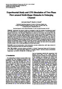
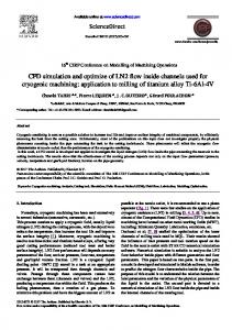
The problem of defining boundary conditions for the whole cylinder is not that simple. The known physical boundary conditions for the cylind er and valve chamber are as follows: I. Known piston velocity (calculated after rotational speed of -3 m/s). 2. Known mean pressure in the valve chamber. This makes it possible to pose the following numerical conditions: I. Conditions of inlet with negative velocity (-3 m/s) at piston head. 2. Conditions of outlet in inlet valve cham ber calcul ated according to mass balance. However, such approach to the problem is impossible because the medium should be treated as compressib le, and for a compressible medium FLUE NT v. 3.03 program allows only pressure boundary conditions. Therefore the calculation procedures were divided into two stages. First, non-c ompressible flow for the conditions mentioned above was considered, nex1 the pressure calculated on the area boundaries was given as boundary conditions for compressible flow through the whole cylinder. The averaging pressure difference at area boundaries for non-compressible case was 5 [kPa] or less dependent on piston position near the cylinder heigh t midpoint. Since this difference can be greater at the valve initial opening, it was decided to perform the calculations in the range of avera ging pressure differences 2 - 24 [kPa], while maintaining the calculated pressure distribution at the area boundary. This procedure made it possible to make a comparison with the results of static tests in which the boundary conditions are pressure values on both sides of the valve. 5. SIMU LATI ON RESULTS FOR INLE T VALV E Fig. I illustrates the distribution of the isobaric conto urs along the whole geometry of the cylinder togeth er with head element for which flow axial symmetry was adopt ed. The results of this simulation were used as bound ary conditions for "zoomed" valve geometry in Cartesian coordinate system. Fig. 2 shows the contours of stream functi on in the valve gap for completely opened valve. The flow separation points are clearly visible. In Fig. 3 there have been compared the characteristics of a valve obtained by means of integr ation in the valve cross-section of the simulated mediu m flow local velocities and experimental tests on inlet valve in the 0 - 25 [kPa] range.
com pres sor head
Pmax= l.e5[Pa]
gap
-=-·
'"0
geom etry
flow direction
C'.r.l
0
symmetry axis
Fig. I. Isobaric lines in the whole cylinder-head geom etry.
429
compressor bead
Fig 2. Stream function lines in the valve gap .
30 (") I
C1l 0
.....
25
•'iij' 20
l:b ~ C1l
....
15
~
10 3: 0
II= Ill Ill
5
co
E pressure difference [kPa]
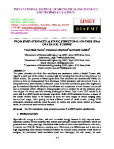
Fig. 3. The comparison of the suction valve characteristic lines. Despite the assumed simplifications, the results of measurements and simulation of the valve characteristic for pressure differences on valve up to 15 [kPa] are quite compatible both quantitatively and qualitatively. For greater pressure differences the results are worse because in case of greater pressure differences the differences between flat and cylindrical geometry are more pronounced. It should be remembered, however, that the simulation was run for a real case with the piston at a midpoint position, the pressure difference on valve being calculated at 5 [kPa], which has been confirmed by numerous tests of the compressor during suction phase. Fig. 4 shows additional simulated characteristics of a valve for air, R 12 and R l34a.
430
'Z
55 50 45
~
-~__......--
0
40 ~ 35 1:>0 30 =. 2 25 f'l 20
g
____...-~ ...-
......-:::.. v
f
15
r
': 10 ~
1/
5
#'
--~
~
..-!-+"'
,...-- ~
a o IV' 0
-
....
5
10 15 pressure difference [kPa]
air '+, rRl2 ""o.... f------' ~.~ Rl34a
20
25
Fig. 4 Suction valve characteristic lines for air, Rl2 and Rl34a. Following the simulation results a change of valve channel cross-se ction was suggested. The aim was to eliminate the flow separation as much as possible and thus to achieve a channel shape closest to the current pattern and feasible in design practice. We also wanted tofind out what theoreti cal effect can be obtained in such an ideal case. Therefore we have deliberately neglected the gap axial symmetry despite technological advantage of such a shape. Fig. 5 illustrates the contours of stream function for such geometry and in Fig. 6 there have been shown the simulated valve characteristics for basic geometry (fig. 2) and the one revised (fig. 5). It is clear that valve throttling was reduced, which means that a given pressure drop on the valve resulted in a much higher mass flow.
compressor head
Fig. 5. Contours of the stream function for improved geometry.
431
pressure difference [kPa] Fig. 6. Compariso n of the characteristic lines for the basic and improved geometry.
6. CONCLUSIONS flow through In the paper it has been shown that the application of CFD simulation in the analysis of It has been work. engineer's design in aid cheap and fast , reciprocati ng compresso r self-acting valves is a convenient the results makes and results correct produces ions, simplificat necessary proved that two-dimen sional simulation , despite medium. working obtained for air transferabl e to any other results by reducing The improveme nt of the valve gap shape according to the stream functions contours produces good valve throttling and thus increasing the valve flow coefficient a. ACKNOW LEDGMEN TS 1369/P4/92/02, the calculations were carried out at TU Delft, Holland, PB project research within The paper was prepared experimen ts performed at Cracow University of Technology. REFEREN CES March 1993. (1] Cyklis P.-"Some Remarks on Refrigeran t Compressors Investigat ion· Rapport no. K-119, TU Delft on of Interaction s Investigati the to Simulation r Compresso of [2] Luszczycki M., Cyklis P., Zelasko J. - "The Application Polish). (in 1993 Poland amics Thermodyn of Congress XV .· Between Valve Work and Pressure Pulsations" Flows" -4th Phoenics [3] Proumen N., Malin M. R., Mendonca F. - "Evaluation of Turbulence Models for In-Cylinde r 1991. Florida Miami, in Internation al User Conference Internal Combustio n [4] Theodorak akos A., Bergels G. - "Prediction of the In-Cylinde r Fluid Motion of a Motored Engine"- Entropie, Nol74/175 , 1993 Through a Channel [5] Price G. R, Botros K.K. - Numerical and Experimen tal Analysis of the Flow Characteris tics Purdue. at Valve"- 1992 Internation al Compressor Engineerin g Conference
432