Change Management Patterns for Software Systems Hannu Jaakkola1? , Kai Jannaschk2?? ,and Bernhard Thalheim2
???
1
2
Tampere University of Technology, P.O.Box 300, FI-28101 Pori, Finland Christian-Albrechts-University Kiel, Computer Science Institute, 24098 Kiel, Germany Abstract. Change management is often considered in software systems development to be an organisational, strategic and administrative issue during software systems development. It does not support the processes beyond requirements engineering. We develop a conceptual model for change management of software systems that covers the entire lifecyle and allows to focus change management within a software development process to individual steps. This model is based on a categorisation of change request, causes for changes, problems observed, and solutions to these problems.
1 Introduction 1.1 Characteristics of Software System Development Software systems are change-sensitive. This feature is built-in to the basic characteristics of them. Information systems typically are built for long time use and in variety of environments by the different users. Changes in software systems are most commonly related to the front-end engineering processes (requirements elicitation and analysis, design). Requirements are tended to change, because the customers do not exactly understand and know their needs. The needs are also changing in time, as well as the importance of them. In addition, new requirements appear as well as the importance of earlier detected ones is lost. Boehm [5] separates two different approaches to software engineering (SE): Plan driven refers to the traditional way of software development. Engineering phases are following each other in sequence and the baseline of every phase is frozen to avoid changes to it. In this sequential development following the water-fall model the requirements baseline acts as a basis for design, design baseline for construction, construction baseline for testing. Even the incremental and iterative modifications of this process implement the same principle - frozen specifications related to every iteration / increment. Plan driven software development can also be called ”contract based” - all is agreed in written contracts and assessed against the project documentation. Agile software development has become popular because reactivity in continuing changes (in requirements) is built-in into the development processes itself. It is based on small increments, short (time) iteration cycles, immediate integration of modules and proximity (active role) of the client during the whole development process. Attitude to documentation also differs from plan-driven culture - only such documentation is produced that is really important for the development work itself. ? ?? ???
[email protected] http://www.pori.tut.fi/∼ hj Corresponding Author:
[email protected] [email protected]
http://www.is.informatik.uni-kiel.de/∼ jannaschk
http://www.is.informatik.uni-kiel.de/∼ thalheim
Boehm’s article [5] does not provide Plan driven and Agile culture as alternatives to each other. In his article [4] Boehm points out five factors indicating suitability of development cultures in development situations: criticality of software, skill level of the personnel, dynamism of the application (requirement changes per time unit), organisation culture and size of development team. To simplify his characterisation, critical software having static requirements is developed by large teams having non-experienced members and the organisation itself has used to work according to predefined rules indicates plan driven culture; the opposite values (non-critical, highly skilled and experienced personnel, dynamics in requirements, work organized in small teams used to chaos) on behalf indicate the suitability of Agile culture. One important factor does not include in the analysis of Boehm - the expected lifespan of information systems. Long lifespan makes software systems susceptible to changes having their origin in the environment (original requirements, platforms, external connections, new interest groups, etc.). The long lifespan also indicates large size and complex architecture of software, which is implemented in layers. Every layer represents its own time. This was seen in year 2000, when the very complex large legacy information systems were updated to fill the needs of the new millennium. Some of them had kernel built already in 1960-1970’ies based on the technology of that time. These components were connected to the more modern parts of the whole by using adaptors. The final result - “a modernised software system” - is a layered structure, in which each layer represents its own time and implementation technology providing a functionality that implements the changes in the system. 1.2 Change Management - Specifications and Discussion In spite of the commonly accepted truth that software systems are in the pressure of continuing changes, Software Engineering literature and standards have not handled the topic in a systematic way. Change management is, however, an essential part of every development step and it relates both in the product itself and the process (Fig. 1).
Fig. 1. The role of change management in software development
Figure 1 illustrates a development path of software pointing out some of the development steps in a process oriented way. The process structure related to software engineering is specified by ISO [1] in its “Software Life Cycle Standard”. This standard introduces seven process groups and altogether 43 processes related to software life cycle. Figure 1 simplifies and completes this structure in two ways to fill better the needs of this paper: we have pointed out the main processes of software development itself (engineering processes), separated the related change management tasks (not included in the standard, as discussed later) and dispelled the other processes of the process standard (not relevant to this paper) on the background (see Figure 1). To find the answer in question “What is change management” we have analysed the above mentioned standard ISO 12207 [1] and the standard ISO 15504-5 [7] that is used to assess the capability level of software processes of an organisation. In addition we used SWEBOK - Software Engineering Body of Knowledge [2] document to find, how change management should be taken into account in SE education. The analysis can be extended to CMM, ITIL, etc. CMM focuses on process change management. ITIL focuses on deployment management. The process standard [1] includes only two minor notifications related to change management. The first one refers to contract change control mechanism. – p. 21: “The contract change control mechanism should address the change management roles and responsibilities, level of formality of the proposed change requests and contract renegotiation, and communication to the affected stakeholders.” – p 111: “The purpose of the Contract Change Management Process is to develop the new contract contents as agreed by both the acquirer and the supplier when a change request affecting the agreed contract contents is proposed. This process begins with a proposal of the change request by either the acquirer or the supplier and ends with the conclusion acceptable for both parties: withdrawal or overall/partial approval of the change request.” The process assessment standard ISO 15504-5 ([7], p. 57) recognises the need of change request as an artifact to manage. A process (SUP.10) is included in the Supporting Processes Group and its purpose is specified: “The purpose of the Change Request Management Process is to ensure that change requests are managed, tracked and controlled.” As a result of successful implementation of it the standard lists1 the following outcomes: (1) a change management strategy is developed; (2) requests for changes are recorded and identified; (3) dependencies and relationships to other change requests are identified; (4) criteria for confirming implementation of change requests are defined; (5) requests for change are prioritized, and resource requirements estimated; (6) changes are approved on the basis of priority and availability of resources; (7) approved changes are implemented and tracked to closure; and (8) the status of all change requests is known. These outcomes are implemented by nine base practices (BP). In addition, the standard defines the need for Problem and Change Management System as a generic resource for the Process Deployment Attribute PA3.2 (p. 91). The standard also gives guidelines for the contents of Change Management Plan (p. 143). To conclude, the detailed guidelines related to change management are in the hands of the organisation and individual developers. 1
This is very similar to those mentioned in ITIL.
The SWEBOK report [2] is developed to give common guidelines on SE education. It points out the importance of requirements’ changes as a part of Software Requirements Subarea (Chapter 2 in the document), which is seen to span the whole software life cycle. It includes change management and maintaining the requirements in a state that accurately mirrors the software to be, or that has been built. The document also notices the importance or recognition the inevitability of change and adopting measures to mitigate the effects of change. Change has to be managed by applying careful requirement tracing, impact analysis and version management. In addition to the Software Requirements Subarea, change management is included as an essential part of Software Configuration Control (Chapter 7). It is concerned with managing changes during the software life cycle. It covers the process for determining what changes to make, the authority for approving certain changes, support for the implementation of those changes, and the concept of formal deviations from project requirements, as well as waivers of them. Information derived from these activities is useful in measuring change traffic and breakage, and aspects of rework. The change control process is defined in detail (p. 7-7). It has the incoming Software Change Request (SCR) as a starting point of the flow, which is controlled by the Configuration Control Board (CCB). Version management is mentioned also in this context with reference to the implementation of the change. A main conclusion of the review above is that the role of change management is tightly bounded to requirements management along the life cycle of software and focused especially in configuration management. Version management - which is a key technology in development phase of software (instead of configuration management)is not handled separately. All changes are seen to have their origin in requirements changes. However, there would be need to change the architecture of software without having special request related to requirements (functional or non-functional), as well as to make changes in the coding practices having its origin in organizing the work. ISO 15504-5 [7] also points out management of process changes in several contexts related to software process capability improvement as well as CMMI. This is left outside the scope of this paper. To conclude, detailed and focused discussion covering change management as a part of individual processes (Figure 1) is missing. The aim of our paper is to provide a systematic conceptual approach to this important topic. 1.3 Results Developed in This Paper This paper starts with a conceptualisation of change management. We develop a model that is cause-driven depending on the category of change requested. It allows a systematic development of solutions for problems that are observed for software systems. This approach uses a pattern structure. A pattern [6] describes a commonly-recurring structure of elements that solve a general problem in a particular context. We derive then templates for handling problems based on separation of concern. The model seems to be very general. In order to show how it can be used for systems we choose database systems. We demonstrate the power of this approach by discussing specific solutions for structural changes. We start with change policies for these templates and use change patterns. For illustration we use database systems.
2 Towards Conceptualisation for Change Management 2.1 The Category-Problem-Cause Model We can classify and manage changes based on the distinction of their causes. The simplest and obvious cause requiring a change is an error, which may relate to design, operation, or organisation. Errors must be corrected. They can occur during application domain description, requirements prescription, software specification as well as during coding. There cannot be any systematic treatment for such. So, we neglect this cause for further consideration. Five main kinds of changes can be distinguished: – The first cause requiring a change is incompleteness (A). A software system operates in an environment (or context), which, following McCarthy [11], we denote by (w, t), where w is a slice of the world at time t. Unfortunately it is rarely possible to determine in advance all the components of w that are relevant, and how the relevant components are expected to evolve over time. It is impossible to determine in advance the effect of these components on a computation, which means that changes due to incompleteness require human intervention. – The second cause requiring a change is based on insufficiency (B) to represent the current knowledge about the application, about technology on hand or other issues such as organisational, social and strategic background. Insufficiency typically leads to so-called workarounds that partially patch or repair a situation. This approach causes another stream of changes. – The third and fourth type corresponds to deviation from normality. Users, system developers, and implementers are biased by the ‘normal’ case and do not keep in mind that states different from the normal ones may occur. The system thus operates well in 80% of operating time and suddenly stops normal operating or suddenly behaves in a way that has not been anticipated. • Changes are caused when lifespan changes (C) are not foreseen. • Another kind of change is caused by overestimation of the normal case. Hidden cases (D) are overlooked but important. – The fifth cause requiring a change is context dependence (E). Systems are not operating on their own. They share resources with other systems, are used in a combined fashion by users, have different maintenance regimes, have different deployment conditions and thus must be considered to be context dependent. This kind of dependence on the system is observed for all engineering disciplines but not properly handled for software systems. Architectures of modern computer systems, solutions to application domain tasks, and code developed under these assumptions and environments are interdependent. Change problems are typically observed at the runtime but must be directly tracked back to the systems development and deployment decisions. For instance, the change category ‘space’ with the problem ‘out of space conditions (storage structures)’ can be tracked back to change causes in the DBMS Oracle ‘poorly forecasted data volumes in physical design’, ‘tablespace fragmentation’, ‘invalid settings for either object space sizes or tablespace object settings’, or ‘not using locally-managed tablespaces’. This Category-Problem-Cause Model is the basis for our solution to develop change-aware systems. It is combined with the characterisation by content, motivation, examples, fit criterion, measurements, and considerations.
2.2 The Category-Problem-Cause-Solution Template for Change Handling Based on these observations made above we may now develop a framework to change handling in a similar form based on the five categories that have been observed so far: (A) Incompleteness of specifications as “modelling gap” [14]: Problem-Cause Solution template incomplete knowledge add neglected specification incomplete coverage develop robust specifications macrodata modelling redesign to microdata library integration complete knowledge on libraries, minimise libraries inability to represent apply explicit replacement specifications missing background data link explicitly to background We may apply procedures for measuring incompleteness of specification, implementation etc. Typical ones are: #represented concepts completeness of schema #application world concepts ,
ree types among application world concepts , capability #conf lict−f #types among application world concepts changes of various types (e.g. correctness), incorrectness of the type system, incorrectness of constructor system, incorrectness of structuring, and incorrectness of static semantics. One of the most difficult incompleteness problems is the current intensive use of libraries. If a library changes then the corresponding code behaviour might change. This has already been a nightmare at PL/1 programming age [8]. It is more severe for current deployment of unknown, partially known or intentionally hidden libraries. (B) Insufficiency to represent the current knowledge in the application domain: Problem-Cause Solution template implementation restrictions extend by theories and languages conceptual language restrictions apply novel theories, advanced logics restricted attention of developers extend scope of reference models non-axiomatisability change logics locality of reasoning use interference reasoning partial change of objects separate stable and transient parts
Insufficiency is treated through concurrent actions and overcoming locality, e.g., mapping to atomic constraint cases. Specific default values can be deployed for problematic cases in domains (e.g., dates misspelled, wrong, not according rules, or doubtful data). Often database types integrate stabile - almost not changing properties and transient - often changing - properties. Objects are however taken as a whole. An approach that might be used in future research is the introduction of robust schema parts based on tolerance and distance to error measures, e.g. metrics: types correctness of schema #correct . #types
(C) Lifespan changes over time due to evolution of system context: Problem-Cause change-sensitive normalisation time overload and mingling non-temporal types too restrictive models instability of schema temporary runtime error
Solution template change of normal form separate kinds of time use temporal types gain flexibility develop dynamic schemata solve similar to 9 kinds of nulls [12]
Database applications as a part of software systems are often assuming certain normal forms. We can however weaken such requirements. For instance, the schema can be separated into a robust sub-schema and an evolving sub-schema. Separation of strong and soft constraints and introduction of “almost valid” constraints supports flexible constraint maintenance. Other facilitation solutions are explicit introduction of time domains and separation of time into its kinds (e.g., transaction, user, validity time). We may introduce temporal types, i.e., explicit volatile types (temporary tables) and explicit virtual types. Flexibility can be achieved through robust schemata. Dynamic schemata can use the explicit introduction of explicit semantics states. In this case, we use state management similar to classical transaction management. (D) Hidden cases due to limiting the consideration to the “normal case” and neglecting the complexity of the application world: Problem-Cause pragmatic assumptions hidden assumptions self-restrictions during development restricted scope of users overlooked cases
Solution template apply explicit modelling use iterative testing detect reasons extend education, sharpening use analysis, verification
Assumptions must be made explicit. They can also be based on the development and programming culture within a community (e.g., dialects of the ER model (Chen, Merise, SERM, HERM styles)). It is necessary to make restrictions explicit. Developers have their own preferences and styles. Iterative modelling can increase robustness. Explicit change and version management allows to track hidden or folklore assumptions. We need to detect reasons for self-restrictions often made by programmers. Another good practice is to broaden the scope of developers with techniques of abstract programming. Techniques that need further research are: control and correction of completeness problems; development of completeness criteria; analysis and verification tools; and predictability of correctness and changes. (E) Context dependence is rather difficult to handle since it depends on the environment. Context-aware programming is rather novel. For instance, compilers optimise expressions in their way without taking into account the order a programmer had in mind while writing the expression.
Problem-Cause Solution template hidden environment use context-aware programming automatic optimisation develop directives for the optimiser operational freedom apply dynamic hints for execution change from test to operational mode analyse defects from test environment consolidation and integration start re-engineering and redesign For instance, database systems rely on automatic optimisation of queries, requests and of maintenance. This optimisation is poly-dimensional and can be directed by directives. Dynamic hints are used for restricting the optimisers’ freedom to choose any query plan. Software is often tested in the testing environment. Later – e.g. for performance reasons – the testing environment is switched off; the system is newly compiled and runs now differently after compilation. The list of category-problem-cause-solution templates is never complete. We show however how a number of solutions can be developed for each singleton case. The list also shows that the cure of each cause problem is thus different. Therefore, self-curation of systems is not feasible for the general case.. The solution templates can not be developed in a general way. We may however specify these templates in dependence on the kind of knowledge. Let us consider database systems as one case. For instance, incomplete knowledge is not only caused by incomplete models but also by non-separation of three parts of the the application: (1) the part of the application that is currently covered by the specification and the model, (2) the part of the application that might be of interest in the future but is not yet covered, and (3) the part of the application that is never be of interest. It is often assumed that only the first and the third part must be considered. But then the second part strikes through and enforces changes that cannot be easily handled. Migration and evolution projects into which we have been incorporated is showed however that a systematic treatment of the second case would have given a chance to avoid evolution problems.
3 Applying the Category-Problem-Cause Template to Database Change Management 3.1 The Change Policy and Change Patterns A change policy is based on a problem description and a chosen change solution. Problems are specified by describing a database state in which a problem occurs, by describing properties of better states, by describing potential actions to change states of a system in general, by goal tests that allow to ascertain whether the problem has disappeared and a problem solution controller that traces future states of the database. The change solution is based on a definition of the solution, an illustration of the solution, examples that illustrate the successful solution and patterns that have been used for the solution. Basic solution patterns specify the required behaviour that should be satisfied under certain conditions, the commanded behaviour that is to be controlled in accordance with commands issued by an operator, the information display for control of the success of the solution states and behaviour information, the simple workpiece used during
solution, and the transformation that must be applied to the system for resolving the problem. There are few examples for general solution patterns so far. We defer the development of solution patterns to future research. We may use a number of change patterns. In this paper we provide details for three basic patterns. The first and third pattern correspond to strategies that have been applied for database migration (chicken little and butterfly). A fourth pattern which could be called big bang pattern [9] seems not to be applicable in change management. Liquefaction of problem area: The problem area is completely gathered with all structures, constraints and functions. The problematic elements are collected in a specific notice board. Then the elements are categorised and composed to database types together with the corresponding integrity constraints. The result is a new database schema. This new database schema allows us to derive an extract-transformload program for transforming a part of the current database to a new one. In parallel rewrite rules for functions are derived. They allow to transform existing functions to new functions. The same kind of rules can also be derived for views. This rule set may be incomplete and for this reason we might have to remain the old part for certain applications. Backward gateways and wrappers [15] provide a basis for a solution to this problem. Change after satisfying observation: The pattern is generalising those used in Ambler [3] and can be considered to a lazy change. It uses two change steps. The intermediate change step transforms the initial model to an intermediate model that is tested in application situations and has a validity deadline. If the validity deadline is reached without a transformation success then the initial model and the initial database are enabled and the intermediate model and databases are disabled. The intermediate model is enhanced by controllers that monitor and control the success of the changes. The finalisation change step transforms the intermediate model to the finalised model and applies this transformation to the application system as well in the case the validity deadline has successfully been reached. Transfer after parallel run: First the current database application is frozen. A solution to the problems is developed and a new solution is going to be developed in the initial step. A set of cluster types [13] is developed for data retrieval. These types allow to retrieve old and new data. The intermediate step uses now both systems in parallel. Any new data or any modified data within the change scope is stored in the new system. In the case of change the old data are removed from the old database. In parallel rewrite rules and extract-transform-load programs are tested within a test environment. In the finalisation step the database and the application functions are taken over to the new system. There are far more patterns known in practice but not yet systematically founded by theory. Pattern are extended by test portfolio which are used for check whether the problem has been solved. The list in Subsection 2.2 results in a set of change patterns. For instance, the last problem and cause in category (B) is often observed as invalid data entry whenever users have to type in data through some interfaces.
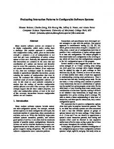
3.2 Elementary Structural Change Templates Elementary structural change steps evolve an existing application model and the corresponding database in small steps at a time to improve the quality of the model and the application without changing static and dynamic semantics, functionality and interaction. For instance, the following structural change templates are used within schemata specified in the extended entity-relationship model: apply operation CUD2 to a type or a constraint. An element under change has a scope that leads typically beyond the element. For instance, a modification of an attribute has also an impact on functions, on other attributes, on views, etc. Structural change templates use the following structure: Problem-Cause-Solution: explicit and refined statement together with the scope; Controller: monitor deviations from expected behaviour and evaluate; Tradeoff: evaluation of the solution after change; Change pattern: applied pattern with database transformation; Function/view/support change mechanics: changes to the entire interface system. Example 1. Let us illustrate elementary change steps for the last problem and cause in category (B). We consider the type Insurance in the application sketched in Figure 3. Insurance
Insurance
Insurance
Attributes:...
All attributes: ... Stable constraints, .... Transient constraints, ... Stable functions, views, ... Transient functions, views
Stable attributes: ...
Constraints, .... Functions, views, ...
6
[event = on CRUD ...] monitor each CRUD to transient [drop date = 30-8-2012]
Stable constraints, .... Stable functions, views, ...
6
Maintain data coherence [policy = materialise] [style = master/slave]
initial model
©©HH © HH Contracting © HH Specifics ©© H H©©
©©HH © HH Contracting © HH Specifics ©© H H©©
Redundant data [event = CUD ...] [finalise date = 30-8-2012]
Transient attributes: ... Transient constraints ... Transient functions, views, ...
intermediate model
final model
Fig. 2. Shifting attributes to subtype in a specialisation hierarchy using unary relationship types
Problem-Cause-Solution: (P) repeated input of data for the type Insurance; difficult to maintain coherence in the insurance contracts; maintenance of integrity constraints; code lookup; specific attribute constraints; repeated low-level descriptions; (C) transient data (insurance company details, agent) are combined with general data (insurance company); 2
create (add), update (modify), drop (delete); CRUD = CUD + retrieve
(S) introduction of a type representing the background data for insurance companies and linking specifics of insurance contracts to the general type; keeping redundant data at new data in a master-slave pattern; Controller: record violations in access to insurance data instead of access to new data; in case of violation send notice and trigger additional changes; Tradeoff: initialisation, changes in performance; Change pattern: change after observation with a change observation period; separate transient and stable data; unary relationship type for IsA relationship; Function/view/support change mechanics: views for combined insurance data; linking facilities for insurance contracts; Figure 2 displays corresponding sub-schemata in the HERM [13] notion. 2EoExample 3.3 Change of a Singleton Model Similar to the elementary case we may develop a number of category-problem-causesolution templates for each of the problem-cause cases in (A), ..., (E). These templates are refined to special templates for each case. For instance, the incompleteness with an incomplete coverage might also be caused by incomplete separation of concern. Schemata with such incompleteness suffer from overloaded types. A change in a schema is seldom applied to a singleton type. It rather uses a subschema which has a border to the rest-schema that remains unchanged and an internal part that is changed. Therefore we start with separating an inner subschema from its border and a rest-schema in a schema. Example 2. Let us consider a simplified application that might be used for managing transportation data which is depicted in Figure 3. We assume that cars which are owned Trading Company
Good
© * ©© © ©H ©© H Retail ¾ © © H H - Car Transport H © H Store H©© ¡ µ @ I ¡ @ ? ¡ @ © H ©H Transport © H © Bill H © H ¡ @© H Insurance H © H © H © H Company H© H©© H Y HH
HH
Insurance ¾ Company
Depository Store
6
- Billing
Company
Fig. 3. Decomposable independent concepts
by owners are used to transport goods from one depository (store) belonging to a supplier to another store (retail store) belonging to a market. The first choice could be a complex relationship type on entity types Car (incorporating ownership data), Transport Company, Marketing Company, Retail Store, Insurance Company, Good (incorporating supplier data), Depository Store and Billing Company. We abstract from all attributes, e.g., from Time for Transport. 2EoExample
Schemata can be analysed based on the quality criteria in the HERM book [13]. Quality optimisation is multi-criteria optimisation and should take into account critical sub-schemata. For instance, a spider subschema has a clique structure in the graph and uses at the same time general cardinality constraints that cannot be expressed by simple lookup and participation cardinality constraints. There is no systematic study on criticality yet. Currently we use heuristical rules for it. Example 3. The schema in Figure 3 has a number of critical points: - Insurances are issued for cars and companies. The transport application is restricted to this kind of insurance. - Billing is typically applied to the entire transportation event. - Cars and owners from the first side, markets and their retail stores from the second side and goods and their depository location are relatively independent from each other. This relative independence is not complete. 2EoExample The change template for structural changes is similar to the one we used in 3.2: Problem-Cause-Solution: (P) spider types in a schema with complex semantics; (C) overloaded combined type that simultaneously represent different facet in combined form; (S) decompose the spider type with redevelopment of subschema; detect layering along cardinality constraints; apply pivoting graph grammar rules and use decomposition graph grammar rule [13]; Controller: monitor exceptions for irregular semantical cases; Tradeoff: loosing flexibility for irregular cases; concentration on stereotyped treatment; Change pattern: decomposition of a complex type using the schema algebra for HERM [10] including introduction of new types; Function/view/support change mechanics: derive views representing spider type; split CUD for spider type into transactions; Example 4. The schema in Example 2 and in Figure 3 is now going to be restructured based on the spider type restructuring template. – We may separate by pivoting rules cars with their owners and insurance from the transport request and transport events. – Marketing companies have their retail stores (RLocation). Goods are stored at a depository store (DLocation). We thus separate these direct associations by pivoting. – A transport request relates goods with their current location to markets with their retail stores. We thus reduce transports to transport requests. – A transport event relates a transport request with a car used for transport. We thus pivot transport events from transport requests. – Billing applies to the transport event and thus relates to the transporting car and the transport request. It inherits thus the transport request. The transformation to a relational schema that does not use identifier attributes for separate types results in a relation schema with markets, their retail stores, goods and their depository stores, cars and additional attributes such as time of the transport event. Billing is issued to the market that requested a transport. We do not assume other kinds of billing.
Retail Store
Good
6
6
Marketing ¾ Company
©HH © © H RLocation H ©¾ HH©©
Billing ¾ Company
HH ©© © H Bill © H © HH ©
Transport ¾ Company
©HH © © H Ownership H © HH©©
©HH © © H TRequest H © HH©© 6
©HH © -© H DLocation H © HH©©
©HH ©TEvent H -© H © HH©© ? -
Car
¾
- Depository Store
Insurance Company
6 ©HH Insurance © © H H © H Contract H©©
©HH Contract © H -© H © H Specifics H©©
Fig. 4. Representation of independent concepts by relationship types
The resulting schema is displayed in Figure 4. This schema is the result of a sequence of operations which also use results from Subsection 3.2: (1) Projection: Cars and transport companies are associated to each other. We may introduce a new type ownership. (2) Shifting: Transports are carried by cars. The ownership for cars is independent. (3) Pivoting: Transports are completed events based on an issuing event such as requests. (4) Multiple shifting: Insurances are issued for cars and are independent from transport events and transport requests. They are assumed to be independent from ownership. (5) Decomposition: Transport requests are considered to relate markets with their retail stores to goods with the location. Therefore, we introduce new types RLocation and DLocation. These new types form the basis for storing data about transport requests. EoExample 2
4 Summary Change handling is often neglected in software projects and currently not considered in a systematic way. Most software engineering approaches do not take into account change handling. Neglecting in his way is correct whenever the specification is complete, whenever the system is correct, whenever the language for specification and coding covers all potential specifics, whenever no changes occur, whenever there are no hidden cases, and whenever the computational environment is entirely in the hands of the programmer team. It seems however that in almost no application this is true. We developed a systematic approach to change handling. This approach is based on a categorisation of changes. Categories can be associated to causes and resulting
problems. We showed that this category-problem-cause model can be extended by corresponding solutions. To become more systematic a change facilitation model must be developed. We may however use the approach given by Tropmann [16] that has been used for sophisticated performance tuning. We show however that by separation into levels the facilitation model is feasible. Beside the detailed formalisation of the facilitation model there are still a good number of open research issues. Open issues are hierarchically structured change sets, general monitors for change sets, tracers and detectors for changes of various categories and changes of changes.
References 1. ISO/IEC/IEEE Standard for Systems and Software Engineering - Software Life Cycle Processes. IEEE STD 12207-2008, pages 1 –138, 2008. 2. A. Abran, J. W. Moore, P. Bourque, R. Dupuis, and L. L. Tripp. Guide to the Software Engineering Body of Knowledge (SWEBOK). IEEE, 2004. 3. S.W. Ambler and P.J. Sadalage. Refactoring databases - Evolutionary database design. Addison-Wesley, 2006. 4. B. Boehm. Some future trends and implications for systems and software engineering processes. Systems Engineering, 9(1):1–19, 2006. 5. B. Boehm. A view of 20th and 21st century software engineering. Software Engineering, International Conference on, 0:12–29, 2006. 6. F. Buschmann, R. Meunier, H. Rohnert, P. Sommerlad, and M. Stal. Pattern-oriented software architecture - A system of patterns, volume 1. Wiley, Chichester, 1996. 7. ISO IEC. ISO/IEC 15504-5, information technology – process assessment – Part 5: An exemplar process assessment model. Assessment, pages 1–206, 2006. 8. Cliff B. Jones, editor. Programming Languages and Their Definition - Hans Bekic (19361982), volume 177 of Lecture Notes in Computer Science. Springer, 1984. 9. M. Klettke and B. Thalheim. Evolution and migration of information systems. In The Handbook of Conceptual Modeling: Its Usage and Its Challenges, chapter 12, pages 381– 420. Springer, Berlin, 2011. 10. Hui Ma, K.-D. Schewe, and B. Thalheim. Modelling and maintenance of very large database schemata using meta-structures. In UNISCON, volume 20 of Lecture Notes in Business Information Processing, pages 17–28. Springer, 2009. 11. J. McCarthy. Notes on formalizing context. In 13th Internat. Joint Conf. Artificial Intelligence, pages 555–560, 1993. 12. K.-D. Schewe and B. Thalheim. NULL value algebras and logics. In Information Modelling and Knowledge Bases, volume XXII, pages 354–367. IOS Press, 2011. 13. B. Thalheim. Entity-Relationship Modeling: Foundations of Database Technology. Springer, Berlin, 2000. 14. B. Thalheim. Towards a theory of conceptual modelling. Journal of Universal Computer Science, 16(20):3102–3137, 2010. http://www.jucs.org/jucs_16_20/towards_a_theory_of. 15. P. Thiran, J.-L. Hainaut, G.-J. Houben, and D. Benslimane. Wrapper-based evolution of legacy information systems. ACM Trans. Softw. Eng. Methodol., 15(4):329–359, 2006. 16. M. Tropmann and B. Thalheim. Performance forecasting for perfomance critical huge databases. In Information Modelling and Knowledge Bases, volume XXII, pages 206–225. IOS Press, 2011.
Acknowledgment. We would like to thank the Academy of Finland and the German Academic Exchange Service (DAAD) for the support of this research.