Channel Impulse Response-based Distributed Physical Layer Authentication Ammar Mahmood∗ , Waqas Aman∗ , M. Ozair Iqbal∗ , M. Mahboob Ur Rahman∗ , Qammer H. Abbasi† ∗ Electrical
arXiv:1703.08559v1 [cs.IT] 24 Mar 2017
engineering department, Information Technology University (ITU), Lahore, Pakistan {ammar.mahmood,waqas.aman,ozair.iqbal,mahboob.rahman}@itu.edu.pk † Department of Electrical and Computer Engineering, Texas A&M University at Qatar
[email protected]
Abstract—In this preliminary work, we study the problem of distributed authentication in wireless networks. Specifically, we consider a system where multiple Bob (sensor) nodes listen to a channel and report their correlated measurements to a Fusion Center (FC) which makes the ultimate authentication decision. For the feature-based authentication at the FC, channel impulse response has been utilized as the device fingerprint. Additionally, the correlated measurements by the Bob nodes allow us to invoke Compressed sensing to significantly reduce the reporting overhead to the FC. Numerical results show that: i) the detection performance of the FC is superior to that of a single Bob-node, ii) compressed sensing leads to at least 20% overhead reduction on the reporting channel at the expense of a small (< 1 dB) SNR margin to achieve the same detection performance.
I. I NTRODUCTION Physical layer authentication addresses the problem of intrusion (impersonation) attack where a legitimate node Alice transmits its data to its intended recipient Bob, while Eve is an intruder node who unlawfully transmits on the channel allocated to Alice, in order to impersonate Alice before Bob. More precisely, for intrusion detection, Bob needs to authenticate each and every data packet it receives from the channel occupant (Alice or Eve). To carry out the (featurebased) authentication, Bob performs binary hypothesis testing while utilizing some device fingerprint (some physical layer attribute) as the decision metric. The (authentication) problem at hand is in principle very similar to the classical problems of detection, classification, clustering etc. Nevertheless, the only important distinction is that in case of authentication problem, the device fingerprint of Eve is unknown. This limitation renders the classical likelihood ratio test (LRT) not computable (and hence Bayesian methods are not directly applicable). Therefore, NeymanPearson based binary hypothesis testing is typically implemented to carry out the authentication task at Bob. As for the decision metric for binary hypothesis testing, Researchers have considered many different physicallayer attributes so far. Broadly speaking, these attributes can be classified into two categories: i) medium-based attributes, ii) hardware-based attributes. Medium-based attributes/fingerprints include different menifestations of the wireless channel such as channel frequency response [1],[2], channel impulse response [3],[4], received signal strength [5],
angle-of-arrival [6] etc. On the other hand, hardware-based attributes/fingerprints include carrier frequency offsets [7],[8], IQ-imbalance [9], mismatch parameters of non-reciprocal hardware [10] etc. In this preliminary work, motivated by the classical distributed detection problem [11], we study the distributed authentication problem. Specifically, we consider a situation where instead of a single Bob (sensor) node, there are N Bob (sensor) nodes which all report their raw measurements or local decisions to a Fusion Center (FC) which makes the ultimate authentication decision. The need for Distributed Authentication arises whenever a single sensor (Bob) node alone can’t be relied upon (e.g., it could come under deep fade/shadowing, it might have excessive AWGN/noise figure due to cheap receive circuitry etc.). Another potential application scenario is that of a Wireless Sensor Network [12] where the sensor (Bob) nodes are primitive in nature (i.e., they can’t do sophisticated signal processing by themselves due to processor, storage and battery constraints); therefore, the sensor nodes simply relay the critical/sensitive data to the FC which carries out the ultimate authentication. Contributions. The main contributions of this paper are the following: i) a preliminary study on distributed authentication, ii) exploitation of compressed sensing at the Bob nodes for significant reduction of the reporting overhead to the FC. Outline. The rest of this paper is organized as follows. Section-II introduces the system model. Section-III provides the necessary background for the channel impulse response which has been utilized as as device fingerprint in this work. Section-IV outlines the details of two strategies Bob (sensor) nodes could adopt to facilitate the cause of distributed detection. Section-V proposes to exploit compressed sensing at the Bob (sensor) nodes to reduce the overhead on the reporting channel. Section-VI provides some numerical results. Section VII concludes. Notations. Bold-face letters (e.g., x) represent vectors; Capitalized bold-face letters (e.g., X) represent matrices; tr(.) denotes the trace operator; (.)T denotes the transpose operator; (.)H denotes the conjugate transpose operator; E(.) denotes the expectation operator; i.i.d implies independent and identically distributed; 0 represents a vector (of appropriate length) of all zero’s; blkdiag(X1 ⋯ XN ) represents a block diagonal
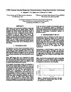
matrix; X ∼ CN (.) signifies that X is a random variable with (circularly-symmetric) complex normal distribution; ∣∣x∣∣lp represents the lp -norm of vector x. II. S YSTEM M ODEL Following the spirits and motivation of distributed detection problem [11], this paper studies the distributed authentication problem whereby N number of Bob nodes simultaneously receive the packet sent by the channel occupant (either Alice or Eve) on the sensing channel (see Fig. 1). The N Bob nodes are either co-located (in the form of an antenna array), or, follow a random geometry (where each Bob node represents a different sensing device). In both scenarios, each Bob node reports some quantity (either its raw measurement, or, its local authentication decision) via a reporting channel to a Fusion Center (FC) which makes the ultimate authentication decision. Inline with previous literature [11], this work assumes that the reporting channel is error-free, delay-free and time-slotted (the performance curves obtained under these assumptions simply become upper-bounds on the performance curves obtained under realistic settings where these assumptions don’t hold).
(i.i.d)
Typically, each of the columns of HAB is modelled as a Complex Gaussian vector; moreover, all the columns (channel vectors) are considered to be i.i.d. However, in this study, we consider a more general/realistic setting; i.e., we assume that the channels measured by all the N Bob nodes are correlated (i.e., either all the Bob nodes are co-located, or, all the nodes in system model of Fig. 1 are located outdoors). Therefore, to (i.i.d) make the columns of the matrix HAB correlated with each other (to exploit the phenomena of compressed sensing later), we leverage the classical Kronecker-product based correlation model [13]. For the system model in Fig. 1, the Kroneckerproduct model reduces to the following: HAB = √
1 tr(RB )
HAB RB 1/2 (i.i.d)
(1)
where RB ∈ RN ×N represents the correlation matrix at the receive side (i.e., the correlation among Bob nodes). Specifically, we employ the exponential correlation model: [RB ]i,j = ρ∣i−j∣ where 0 ≤ ρ ≤ 1 is the correlation amount and i, j represent row and column indices of RB (or, Bob i and Bob j) respec∆ tively. Then, one can write: HAB = [hA,B1 hA,B2 ⋯ hA,BN ]. Similarly, when Eve transmits on the shared sensing channel, then one can define: (i.i.d) ∆
HEB
= [hE,B1 hE,B2 ⋯ hE,BN ] ∈ C(L×N ) (i.i.d)
(i.i.d)
(i.i.d)
∆
The channel matrix HEB = [hE,B1 hE,B2 ⋯ hE,BN ] with correlated columns is then constructed via Eq. (1) as well1 . IV. D ISTRIBUTED AUTHENTICATION
Fig. 1.
The Distributed Authentication problem.
III. BACKGROUND : C HANNEL I MPULSE R ESPONSE AS D EVICE F INGERPRINT An intrusion (impersonation) attack occurs when an intruder node Eve unlawfully transmits on the (sensing) channel allocated to legitimate node Alice so as to impersonate Alice before Bob. To counter the challenge of intrusion attack, Bob needs to do authentication of each and every data packet it receives. Motivated by [4], this work utilizes the channel impulse response (CIR) as the device fingerprint for the purpose of authentication (at Bob nodes, or, Fusion center). More precisely, this work considers a single-carrier, wideband system with a time-slotted sensing channel (with τ seconds long timeslots). To introduce the notations, let’s assume that Alice transmits on the shared sensing channel; then Bob n sees the (i.i.d) (i.i.d) channel hA,Bn . More precisely, hA,Bn is the channel impulse (i.i.d) response, i.e., hA,Bn = [hA,Bn (1) hA,Bn (2) ⋯ hA,Bn (L)]T where n = 1, ..., N and L represents the total number of channel taps for the considered multipath (i.e., frequencyselective), time-invariant channel. Define: (i.i.d) ∆
HAB
= [hA,B1 hA,B2 ⋯ hA,BN ] ∈ C(L×N ) (i.i.d)
(i.i.d)
(i.i.d)
This section outlines the proposed distributed authentication framework which in turn utilizes the channel impulse response as the transmit device fingerprint. During m-th timeslot, either Alice, or, Eve will transmit on the sensing channel (assuming that Eve avoids collisions so as to stay undetected). Therefore, when Bob n receives a packet from the channel occupant (CO) (where CO ∈ {A, E}), it independently generates a measurement zn (m) of its local CIR hCO,Bn as follows [4]: zn (m) = hCO,Bn + vn (m)
(2)
where vn (m) is the measurement noise. Specifically, vn (m) ∼ CN (0, Σn ) where Σn = σn2 (SH S)−1 ∈ RL×L ; σn2 denotes the variance/power of the AWGN at Bob n. Furthermore, we assume that vn (m) (n = 1, ..., N ) are i.i.d2 . With the raw measurements of local CIR available at each Bob node, two distinct strategies are possible: i) each Bob node sends its raw measurement as is (along with the ground truth) to the FC, ii) each Bob node does the authentication locally and sends its binary decision to the FC. Both strategies are discussed below. 1 At this point, it is worth mentioning that we haven’t incorporated the transmit side correlation (between Alice’s antenna and Eve’s antenna) into the Kronecker product model. The reason for this is that, inline with the previous work [1], we assume that Alice and Eve are spaced far apart (more than one wavelength) so that their mutual correlation is negligible. 2 S is the matrix formed by the training symbols. See [4] for more details.
A. Each Bob node sends its raw measurement as-is to the Fusion Center Under this scenario, each Bob node sends its raw measurement zn as-is (along with the ground truth) to the FC3 . Since an error-free, time-slotted reporting channel is assumed, FC receives all the (perfect) measurements after N time-slots (of the reporting channel). Fusion center then constructs a global ∆ measurement vector z∗ = [zT1 zT2 ⋯ zTN ]T . Then, we can write: z∗ = hCO,B∗ + v∗ (3) ∆
∆
where hCO,B∗ = [hTCO,B1 hTCO,B2 ⋯ hTCO,BN ]T and v∗ = T T [v1T v2T ⋯ vN ] . v∗ represents the global estimation error; v∗ ∼ CN (0, Σ∗ ) where Σ∗ = blkdiag(Σ1 Σ2 ⋯ ΣN ) ∈ R(L×N )×(L×N ) . With z∗ available, the FC casts the sender-node authentication problem as a binary hypothesis testing problem: ⎧ ⎪ ⎪H0 ∶ ⎨ ⎪ H ∶ ⎪ ⎩ 1
z∗ = hAB∗ + v∗ z∗ = hEB∗ + v∗
(4)
where hAB∗ = [hTA,B1 , hTA,B2 , ..., hTA,BN ]T and hEB∗ = [hTE,B1 , hTE,B2 , ..., hTE,BN ]T . Then, z∗ ∣H0 ∼ CN (hAB∗ , Σ∗ ) and z∗ ∣H1 ∼ CN (hEB∗ , Σ∗ ). If H0 = 1, received data (on the sensing channel) is accepted by the FC; if H1 = 1, received data is discarded by the FC. Next, assuming that hAB∗ is known to the FC (via the prior training of the Bob nodes, on a secure channel) with sufficient accuracy, the FC applies the following test [4]: H1
(z∗ − hAB∗ )H Σ∗ −1 (z∗ − hAB∗ ) ≷ δ
(5)
H0
where δ is the comparison threshold whose value is to be determined by the FC. This work follows Neyman-Pearson procedure to systematically compute the threshold δ. Specifically, δ is computed from a pre-specified, maximum Type-1 error (i.e., probability of false alarm, Pf a ) that the FC can tolerate. Then, for a given Type-1 error, Neyman-Pearson method guarantees to minimize the Type-2 error (i.e., probability of missed detection, Pmd ). Denote by T the test statistic in Eq. (5); i.e., T = (z∗ − hAB∗ )H Σ∗ −1 (z∗ − hAB∗ ). Then, the test statistic T ∣H0 ∼ χ2 (2N L); i.e., T has central Chi-squared distribution with 2N L degrees of freedom, under H0 . Then, the probability of false alarm Pf a (i.e., incorrectly identifying Alice’s packet as if it is from Eve) is given as:
probability of missed detection: Pmd = P r(T < δ∣H1 ). Since computing the distribution of T ∣H1 is quite involved, we numerically compute the value of Pmd in simulation section. B. Each Bob node sends its local decision to the Fusion Center Under this scenario, Bob node n (independently) utilizes its measurement zn of its local CIR hCO,Bn (see Eq. (2)) to construct the following binary hypothesis testing problem: ⎧ ⎪ ⎪H0 ∶ zn = hA,Bn + vn ⎨ (7) ⎪ H ∶ zn = hE,Bn + vn ⎪ ⎩ 1 Once again, assuming that hA,Bn is perfectly known to Bob n, it applies the following test [4]: H1
(zn − hA,Bn )H Σ−1 n (zn − hA,Bn ) ≷ δn
(8)
H0
where δn is the comparison threshold whose value is to be determined by Bob n. Once again, we follow the NeymanPearson procedure to systematically compute the threshold δn . Denote by Tn the test statistic in Eq. (8); i.e., Tn = (zn − hA,Bn )H Σ−1 n (zn − hA,Bn ). Then, the test statistic Tn ∣H0 ∼ χ2 (2L); i.e., Tn has central Chi-squared distribution with 2L degrees of freedom, under H0 . Then, the probability of false alarm Pf a,n is given as: Pf a,n = P r(Tn > δn ∣H0 ) = ∫
∞ δn
pTn ∣H0 (x)dx
(9)
where pTn ∣H0 (x) ∼ χ2 (2L) is the probability density function of Tn ∣H0 . Thus, one can set Pf a,n to some value αn in Eq. (9) and solve for the threshold δn . With Pf a,n = αn , the performance of the hypothesis test in Eq. (8) is solely characterized by the Type-2 error a.k.a the probability of missed detection: Pmd,n = P r(Tn < δn ∣H1 ). Since it is difficult to compute the distribution of Tn ∣H1 , we numerically compute the value of Pmd,n in simulation section. Then, the Fusion Center, having received the vector of local (binary-valued, hard) decisions u∗ by all the Bob nodes, applies the following (heuristic) fusion rules to generate the ultimate (binary-valued, hard) decision: i) OR (optimistic) rule, ii) AND (pessimistic) rule, iii) majority voting, iv) weighted averaging. V. OVERHEAD R EDUCTION ON R EPORTING C HANNEL VIA C OMPRESSED S ENSING
where pT ∣H0 (x) ∼ χ2 (2N L) is the probability density function of T ∣H0 . Thus, one can set Pf a to some value α in Eq. (6) and solve for the threshold δ. With Pf a = α, the performance of the hypothesis test in Eq. (5) is solely characterized by the Type-2 error a.k.a the
This section attempts to invoke Compressed Sensing4 at the Bob nodes owing to the fact that the CIR measurements made by the Bob nodes are correlated (see Eq. 1). To this end, this section focuses on a specialized system model (more than the one given in Fig. 1 earlier) whereby the N (N is large) Bob nodes are all co-located as a linear antenna-array on a single receive device, now-called the relay node. Such system model could represent, for example, a situation where a
3 For clarity of exposition, we drop the time-slot index m in the rest of this paper.
4 The interested reader is referred to [14] for a comprehensive overview of compressed sensing.
Pf a = P r(T > δ∣H0 ) = ∫
δ
∞
pT ∣H0 (x)dx
(6)
y = Φz∗
(10)
where Φ ∈ R(M ×N L) is a random matrix, the so-called sensing/measurement matrix, whose entries are typically the realizations of i.i.d Gaussian or Bernoulli variables. After the compression, the relay node transmits the vector y to the FC in M time-slots. Due to the error-free reporting channel, the FC receives y as-is; therefore, its task becomes to ˆ∗ of z∗ from y. To this end, we invoke recover an estimate z the classical Orthogonal Matching Pursuit (OMP) algorithm at the FC [16]. Specifically, the OMP solves the following l1 -norm minimization problem:
where
min ∣∣z0 ∣∣l1 s.t. y = ΦΨT z0
(11)
z0 = Ψz∗
(12)
is the actual K-sparse representation of z∗ in a transform domain. The matrix Ψ is called the sparsifying basis. The most 5 For
example, [15] presents a scheme where during each of the M timeslots, each of the N sensor nodes transmits its local measurement to the FC with some probability p, thus making the sensing/measurement matrix Φ non-Gaussian.
B. The relay node compresses the vector of local decisions and sends it to the Fusion Center Under this strategy, the relay node compresses the vector of local decisions u∗ ∈ {0, 1}(N L×1) into a vector y ∈ {0, 1}(M ×1) (M