Thus, the syllable is a universal primary minimal undivided basic phonetic unit ...
Various theories of syllable formation and syllable division exist. One of the.
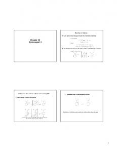
Amines-part 2. ◇ Lone pair on the nitrogen directs the chemistry of amines ...
Nitrous acid (HONO) is prepared in situ by reaction of sodium nitrite with a strong
...
TERMINOLOGY: The term “degrees of certainty” is used with those modals that ...
grammars, terms such as “logical possibility” or “degree of probability” are ...
(ASTM D 854-92) ... d. Use the thermometer to determine the water temperature
to the .... the test method specific to wet preparation of soil samples (ASTM D.
because he fought with a security guard. In another ... PNR in Malong vs Philippine National Railways although ... Displ
In Peril on the Sea – Episode Five. Chapter 2Part 1. LONG, SLOW YEARS: THE
ROYAL CANADIAN NAVY. BETWEEN THE WARS, 1919 - 1939. New Arrivals ...
At first, Miko had recorded 'sentences' as atomic (indivisible) units: (1) a. megfedkim b. kimizâsliip. SENTENCE SENTE
spite the popularity of tools that allow chat, a recent declara- ... There are several studies that look at tech- .... with research, homework, technical support, etc.
Fundamental Data Structure in Computer Science. • Many examples to follow ...
Graph Theory History: The K¨onigsberg bridge problem. • Solved by Euler ...
5. For copy of the video, please contact the speaker: Eliot Siegel, M. D., Director,
Baltimore. Veterans Affairs Medical Center Radiology ...
Jan 6, 2011 ... Digital Logic Design using Verilog and FPGA ... Verilog allows us to design
circuits, FPGAs .... Design Using Digilent FPGA Boards ─ Block.
Alfandari/Nardone, Associations et fondations en Europe (1994) ....................................... 48. 2. Communication of the Commission on Promoting the Role of Voluntary Organizations ...... 47 IMF, World Economic Outlook Database, data for 20
Department of Electromechanical Engineering, Shijiazhuang Institute of Railway Technology, Shijiazhuang 050041, P.R. China. (Manuscript Received April 6, ...
15 And He made a scourge of cords, and drove them all out of the temple, with the ... 14 âAs Moses lifted up the serpe
Oct 1, 2002 ... Part 2 provides background information in support of Part 1 and will assist in ...
The Horizontal odour guidance - Parts 1 and 2 – provide an ...
equipment and innovation, production, innovation and marketing activities have ..... Innovation manager in South Africa affiliate ...... 8 http://www.facebook.com/#!
Hm»T .fallos en las post-ao, aŕgmee eelroaîeroe todavía ..... importmites, que se
hog-roi simulacros c ensayos de galones de emergencia, tg mor medidos con ...
AX 8005] as galll- Language 3, Dramatic 1, Art 1,. Anti-Superstition 1, Student
Council 1,. Band 3. Annual Staff (Editor), Girls'. Statu, Attendant to Homecoming ,.
Chopra (UWC Public Health Programme), Tania Vergnani (UWC, Facuity of
Education), Benito Mayosi. (KTT), John Fincham (MRC), Lori Lake (ESST), Edgar
...
Based on excerpts from Zen and the Art of Motorcycle Maintenance: An Inquiry
into Values [R. Pirsig]. Part 2 – Challenges to Quality. Getting Stuck. "I want to ...
you type LINK -S. You can also have the linker create your .... used by each
machine language instruction. ...... read the instructions in the corre sponding
article.
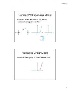
Feb 5, 2013 ... Design a circuit to provide output voltage of 2.4V. (0.7 V at 1 mA). Small Signal
Model. Microelectronic Circuits,. Sixth Edition. Sedra/Smith.
Feb 23, 2015 ... Advanced, Fifth Edition by Wayne Tomasi – Chapter 2. (https://www.goodreads.
com/book/show/209442.Electronic_Communications_System)
Chapter 2 – Part 2 Liner System Review, DFT & FFT Updated:2/23/15
Outline • Review of linear systems • Sampling theorem • Fast Fourier Transform
Linear Time Invariant System (LTIS) - 1 L is a Linear Operation
Example: y(t) = t – 3 Is a linear time invariant system
Linear Time Invariant System (LTIS) - 2
h(t)
δ(t)
δ(t-7t) Δt
tà n=1 2 3 4 5 6 7 8 .... N
Linear Time Invariant System (LTIS) - 3
This is called the convolution integral!
Linear Time Invariant System (LTIS) - 4
Example: Linear Time Invariant System (LTIS) - 5
power transfer function (or power gain) of the system
Example: RC Low-Pass Filter Characterization
See Fourier Pair Table (Exponential one-sided)
10log(|H(f)|^2)=0dBßà 1.0
10log(|H(f)|^2)=10log (0.5)=-3dBßà 0.5
When f=foà G(fo)=0.5à-3dB attenuation
Distortionless Transmission -1 • An LTI system is termed distortionless if it introduces the same attenuation to all spectral components and offers linear phase response over the frequency band of interest:
Ho is the gain (or attenuation!) If Ho is unity then there is no lossà Lossless system We refer to to as the Td or time delay
Distortionless Transmission -2
Note that the phase response is a linear function of frequency in LTI! Group delay: refers to time delay that difference spectral components experience!
Distortionless Transmission -3 • The phase delay of an LTI system is defined as
• For a LTI system
(from before)
Is the Output of an RC Filter Distortionless? Remember, for RC filter:
-
Introducing both amplitude and phase distortion! …see next
Is the Output of an RC Filter Distortionless? Amplitude distortion if the amplitude response is not flat
Range of frequencies ( 2B • Δf is frequency resolution = 1/T • f represents the frequency points = n/T ; n = [0,1,2, N-1]
Sampled Windowed waveform and its magnitude spectrum – fs=1/dt
Periodic Sampled Windowed waveform and its magnitude spectrum – fs=1/dt=N/T & dt=T/N (or Period T = N.dt) & fo=1/To
X(n) is the DFT
Using FFT to find the DFT - MATLAB Example M = 7; N = 2^M; % Using zero padding n = 0:1:N-1; T = 10; % period dt = T/N; t = n*dt;
% sampling period % simulation time
Tend = 1
T=10
Zoomed to f = [0, 4]
% Creating time waveform % w=Your waveform! % Calculating FFT W = dt*fft(w); f = n/T; plot(t,w); plot(f,abs(W); plot(f,180/pi*angle(W));
Pos. Freq.
Neg. Freq.
Using DFT to Compute the Fourier Series w
w
Example (MATLAB Implementation)
We use the DFT (FFT) to approximate the spectrum continuous W(f) & evaluate the complex Fourier series coefficients cn
Example (MATLAB Implementation) fo=10
Magnitude Spectrum: |Cn|
10Hz
70Deg. @ 10Hz
Note f=n*fo=10
References • Leon W. Couch II, Digital and Analog Communication Systems, 8th edition, Pearson / Prentice, Chapter 1 • Electronic Communications System: Fundamentals Through Advanced, Fifth Edition by Wayne Tomasi – Chapter 2 (https://www.goodreads.com/book/show/209442.Electronic_Communications_System)