features helps to understand how hierarchical, modular simulation models are
speci ed in DEVS-. Scheme. 1 Discrete Event Dynamic. Systems. Discrete event
...
33
Chapter 3: DEVS FORMALISM and DEVS-SCHEME
This chapter reviews the DEVS formalism and its implementation in DEVS-Scheme. Although we don't dwell on the mathematical properties of the DEVS formalism, understanding its basic features helps to understand how hierarchical, modular simulation models are speci ed in DEVSScheme
1 Discrete Event Dynamic Systems Discrete event modeling is nding ever more application to analysis and design of complex manufacturing, communication, and computer systems among others. Long overdue recognition of the importance of the eld emerged with the publication of a special issue on DEDS (Discrete Event Dynamic Systems) edited by Yu-chi Ho (1989). Powerful languages and workstations been developed for describing such models for computer simulation (see Garzia et. al. 1986 for a general review). Yet general understanding of the nature of discrete event systems per se (as distinct from their computer representations) is still in relative infancy compared to that of continuous systems.
1.0.1 A bit of history
Di�erential equations employed to describe continuous systems have a long history of development whose mathematical formalization came well before the advent of the computer. In contrast, discrete event simulations were made possible by, and evolved with, the growing computational power of computers. The prime requirement for conducting such simulation was to be able to program a computer appropriately. Not of immediate utility, computer-independent model description formalisms for discrete event systems, paralleling the di�erential equations for continuous systems, were late in coming. Yet, it is now being recognized that our understanding of complex systems may be greatly enhanced with such mathematically based formalisms. Since the early 70's work has been proceeding on a mathematical formalism for modeling discrete event systems. One approach, inspired by the systems theory concepts of Zadeh and Dosoer (1963), Wymore (1967), Mesarovic and Takahara (1975), and Arbib and Padulo (1974), attempted to cast both continuous and discrete event models within a common systems modeling framework. This approach was elaborated in a number of publications primarily summarized in the books (Zeigler, 1976) and (Zeigler, 1984), and is reviewed in (Zeigler, 1985). Systems modeling concepts were an important facet in a movement to develop a methodology under which simulation could be performed in a more principled and secure manner (see for example O ren et:al, 1984). The recent advent of high performance arti cial intelligence software and hardware has facilitated the transfer of this simulation methodology from research to practice (Elzas et:al: 1986).
Models, Knowledge and Endomorphy
34
1.0.2 The DEVS approach
The Discrete Event System Speci cation (DEVS) formalism introduced by Zeigler (1976) provides a means of specifying a mathematical object called a system. Basically, a system has a time base, inputs, states, and outputs, and functions for determining next states and outputs given current states and inputs (Zeigler, 1984b). Discrete event systems represent certain constellations of such parameters just as continuous systems do. For example, the inputs in discrete event systems occur at arbitrarily spaced moments, the inputs in discrete event systems occur at arbitrarily spaced moments, while those in continuous systems are piecewise continuous functions of time. The insight provided by the DEVS formalism is in the simple way that it characterizes how discrete event simulation languages specify discrete event system parameters. Having this abstraction, it is possible to design new simulation languages with sound semantics that easier to understand. Indeed, the DEVS-Scheme environment to be described later is an implementation of the DEVS formalism in Scheme (a Lisp dialect) which enables the modeler to specify models directly in its terms. DEVS-Scheme supports building models in a hierarchical, modular manner described above. This is a systems oriented approach not possible in popular commercial simulation languages such as Simscript, Simula, GASP, SLAM and Siman (all of which are discrete event based) or CSMP and ACSL (which are for continuous models). 1 The DEVS formalism is more than just a means of constructing simulation models. It provides a formal representation of discrete event systems capable of mathematical manipulation just as di�erential equations serve this role for continuous systems. Such manipulation includes behavioral analysis whereby properties of the behavior of a system are deduced by examining its structure. Although this is an area of intense investigation, such analysis is di�cult { we return to this thought in a moment. Therefore, direct computer simulation will remain a primary means of generating, and studying, model behavior. However, other kinds of processing, are equally important: mathematical representations may be compared, transformed into other forms, simpli ed, decomposed and reconstituted in a great variety of ways (O ren, 1987c; Pichler, 1986). Much of this type of processing can be automated within a symbol manipulation such as Scheme, as we shall see.
1.0.3 DEVS in relation to other approaches
A number of other approaches to modeling DEDS are brought together in the above-mentioned special issue (Ho, 1989). Many are algebraic or graphical in character and do not include the time element that DEVS inherits from its system theoretic origins. The most closely related formalisms are those emerging under the framework of Generalized Semi-Markov Processes (GSMP), in which we can include the stochastic generalizations of Petri Nets (Sanders, 1988; Meyer et:al:, 1985). GSMP , as formulated by Glynn (1989) and Cassandras and Strickland (1989), attempt to formalize discrete event simulation models as Markov processes with countable state sets that are amenable to mathematical analysis. The relationship between DEVS and GSMPs needs to be 1 DEVS-Scheme can be used to map into such languages however; see Appendix A.1.
Models, Knowledge and Endomorphy
35
Real or Proposed System
Simulator
modeling
simulation
Model
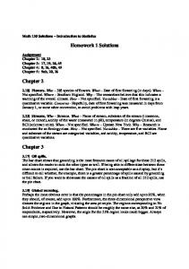
Figure 1: Entities and relations in simulation explored. However, in Appendix B, we show that DEVS appears to the more powerful formalism, trading mathematical tractability for expressive power. Chapter 14 provides an in-depth comparison of DEVS-Scheme with other knowledge-based simulation environments.
2 Brief Review of the DEVS Formalism Figure 3.1 depicts the conceptual framework underlying the DEVS formalism (Zeigler, 1976). The modeling and simulation enterprise concerns three basic objects:
� the real system, in existence or proposed, which is regarded as fundamentally a source of data � the model, which is a set of instructions for generating data comparable to that observable in the real system. The structure of the model is its set of instructions. The behavior of the
Models, Knowledge and Endomorphy
36
model is the set of all possible data that can be generated by faithfully executing the model instructions. � the simulator which exercises the model's instructions to actually generate its behavior. The basic objects are related by two relations:
� the modeling relation, linking real system and model, de nes how well the model represents
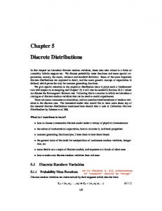
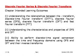
the system or entity being modeled. In general terms a model can be considered valid if the data generated by the model agrees with the data produced by the real system in an experimental frame of interest. � The simulation relation, linking model and simulator, represents how faithfully the simulator is able to carry out the instructions of the model. There is a crucial element which must be brought into this picture { the experimental frame.2 This captures how the modeler's objectives impact on model construction, experimentation and validation. As we shall see later, in DEVS-Scheme, experimental frames are formulated as model objects in the same manner as the models of primary interest. In this way, model/experimental frame pairs form coupled model objects with the same properties as other objects of this kind. It will become evident later, that this uniform treatment yields immediate bene ts in terms of modu (1989b). larity and system entity structure representation. For an alternate formulation, see Oren The basic items of data produced by a system or model are time segments. These time segments are mappings from intervals de ned over a speci ed time base to values in the ranges of one or more variables. The variables can either be observed or measured. An example of a data segment is shown in Figure 3.2. The structure of a model may be expressed in a mathematical language called a formalism. The discrete event formalism focuses on the changes of variable values and generates time segments that are piecewise constant. Thus an event3 is a change in a variable value which occurs instantaneously as shown in Figure 3.3. 2 The interpretation of the experimental frame concept in simulation languages is still evolving. GEST (O ren,
1984) was the rst conceptual language to sharp distinguish model and experiment speci cations. SIMAN (Pedgen, 1983) was the rst commercial, language to incorporate a modicum of separation between model and experimental frame along the lines suggested by Zeigler (1976) and O ren and Zeigler (1979).
The uniform treatment of experimental frame objects and models objects in DEVS-Scheme implements a more recent formalization (Zeigler, 1984). The situation is somewhat complicated in continuous simulation where execution control parameters, such as step size and communication interval, can be considered to be part of the experimen (1989b), execution control tation speci cation. In contrast to perhaps a more widely held view expressed by Oren speci cation should be not be included in the experimental frame. The implementation of continuous simulation within DEVS-Scheme by Wang (1989) shows how this can be done (see Appendix A.1). 3 We distinguish events, which are changes in value, from event generating mechanisms. The latter are simulation constructs (e.g., event routines) that at certain (scheduled) times determine whether an event actually occurs and what new values for variables are established.
Models, Knowledge and Endomorphy
Figure 2: Generalized data segment produced by a system or model.
37
Models, Knowledge and Endomorphy
Figure 3: Discrete event time segment.
38
Models, Knowledge and Endomorphy
39
In essence the formalism de nes how to generate new values for variables and the times the new values should be take e�ect. An important aspect of the formalism is that the time intervals between event occurrences are variable(in contrast to discrete time where the time step is a xed number).
3 Basic Models In the DEVS formalism, one must specify 1) basic models from which larger ones are built, and 2) how these models are connected together in hierarchical fashion. In this formalism basic models are de ned by the structure M = hX; S; Y ,� ,� , �,tai where X is the set of external input event types, S is the sequential state set, Y is the set of external event types generated as output, � (� ) is the internal (external) transition function dictating state transitions due to internal (external input) events, � is the output function generating external events at the output, and t is the time-advance function. Rather than reproduce the full mathematical de nition here (Zeigler, 1984), we proceed to describe how it is realized in DEVS-Scheme. int
int
ext
ext
a
To specify modular discrete event models requires that we adopt a di�erent view than that fostered by traditional simulation languages. As with modular speci cation in general, we must view a model as possessing input and output ports through which all interaction with the environment is mediated. In the discrete event case, events determine values appearing on such ports. More speci cally, when external events, arising outside the model, are received on its input ports, the model description must determine how it responds to them. Also, internal events arising with in the model,change its state, as well as manifesting themselves as events on the output ports to be transmitted to other model components. A basic model contains the following information:
� the set of input ports through which external events are received � the set of output ports through which external events are sent � the set of state variables and parameters: two state variables are usually present{ phase and sigma (in the absence of external events the system stays in the current phase for the time given by sigma) � the time advance function which controls the timing of internal transitions{ when the sigma state variable is present, this function just returns the value of sigma. � the internal transition function which speci es to which next state the system will transit
after the time given by the time advance function has elapsed � the external transition function with speci es how the system changes state when an input is received- the e�ect is to place the system in a new phase and sigma thus scheduling it for
Models, Knowledge and Endomorphy
40
Figure 4: Simple bu�ering model. a next internal transition; the next state is computed on the basis of the present state, the input port and value of the external event, and the time that has elapsed in the current state. � the output function which generates an external output just before an internal transition takes place.
3.1 Pseudo-code description of basic models
A pseudo-code facilitates such model speci cation and its expression within DEVS-Scheme. Each input port requires speci cation of an external transition, in the form of a when receive x on input port p . . . phrase. The internal transition function can be speci ed in the form of a process-like description with phases and their transitions. The output function uses phrases of the form send y to output port p. As an example, consider a simple bu�ering model in Figure 3.4a. There are three input ports: in, for receiving items to be bu�ered, done, for receiving the acknowledgment of the down stream process, and stop send for ow control from the up stream process. The output port out, is for sending items down stream. The pseudo-code description is in Figure 3.4b. The pseudo-code makes use of the variables e (elapsed time in current phase) and � (time left in current phase) which are essential to achieving modularity in discrete event models. These variables are assumed to be managed by the simulation executive. Although, such management takes the
Models, Knowledge and Endomorphy
41
form of a global event list in the case of conventional simulation languages, other implementations, such as that in DEVS-Scheme, may be more advantageous in conventional as well as multiprocessor simulation architectures. Note that the external transition speci cation has three when receive phrases, one for each input port. The rst says that when an input value x is received on the in port, it should be inserted in a queue; if it is the only member of the queue, control should be sent to the phase SEND, otherwise the model should continue(no new internal event will be scheduled). The internal transition speci cation has only one phase, SEND, in which the model stays for a period, preparation-time| this causes the scheduling of an internal transition to occur at time = current time + preparationtime. Upon occurrence of the event, the model sends the rst value in its queue to the output port out, removes it from the queue, and then passivates. The PASSIVE phase (in which the model passivates) represents a \ground" phase of the model in which it waits for external events while engaging in internal activity of its own. The phrase \continue" indicates that the time remaining in the phase in which the model nds itself is not to be changed as result of the external event processing. To express an interruption requiring a change in scheduling we replace continue statements by those manipulating � , as the speci cation for the input port stop send shows. This external event, if indicating stop, causes the model to leave phase SEND, where it is holding, and abort the current transmission; if indicating start, transmission is re-initiated. Change in scheduling is brought about as � is changed from a nite value to in nity in the rst case. Supposing that the time already spent in preparing the output need not be repeated when transmission is resumed, we store the remaining time (� - e) in processing-time-left for restoration to � upon re-entry to the SEND phase. Were there several jobs that could be in suspended states of this kind at once, we would save a processing-time-left with each one.
3.2 DEVS-Scheme Implementation of DEVS basic models
In the DEVS-Scheme realization, the DEVS formalism is re ned so that both the input and output sets X,Y consist of pairs of the form (port,value). Thus, an external input event of the form x = (p,v) signals the fact that a value v has been received at an input port p. Similarly, y = (p,v) represents the sending of a value v to output port p. Port-value pairs are speci ed using the structure de nition: (de ne-structure content port value). This de nition creates a template for a structure type named content so that an instance may be created using the make-content function. The slots port and value are accessed using the contentport and content-value procedures created by Scheme.
C++:
Models, Knowledge and Endomorphy
42
Models, Knowledge and Endomorphy
43
class content:public entity{ public: port * p; entity * devs; addrclass * address; entity * val; }
The set-theoretic components of the DEVS formalism take the form of Figure 3.5. Due to the absence of typed variables, the abstract input, state and output sets of the formalism cannot be completely characterized in Scheme. Indeed, this fact makes it possible for DEVS-Scheme to be completely general. However, the four basic functions are expected to receive and return arguments consistent with the DEVS formalism as indicated in Figure 3.5. To illustrate consider a simple model (itself of no signi cance beyond illustration). The model state is numerical, each internal transition causes a doubling in value; internal transitions occur every 1 unit. Formally, S = Reals � (s) = 2 * s t()=1 int
a s
In DEVS-Scheme, this model is represented by the de nitions: (de ne (int s) (* 2 s)) (de ne (ta s) 1) Note that (int s) will yield a numerical value so long as s is initially set to a number. This meets the requirement that the internal transition function map values from the state set back into itself. Similarly, (ta s) always returns a non-negative number (namely, 1) as required by the formal de nition. Let us add an external transition function which causes the input value to be added to the current state:
�
ext
(s e x) = s + x.
Note that the external transition function has three arguments: s (the current state), e (the elapsed time in this state), and x (the external input causing this event). 4 The DEVS-Scheme representation is: (de ne (ext s e x) (+ s (content-value x))) Note that the input x is expected to be in the form of a content structure as indicated above. Moreover, the value eld in this content structure must be a number for the addition to the current 4 The fact that the arguments spell a popular three-letter word is purely co-incidental!
Models, Knowledge and Endomorphy
44
Figure 5: How the set theoretic components of the basic DEVS formalism are realized in DEVSScheme.
Models, Knowledge and Endomorphy
45
state to make sense. For example, we might generate such a content structure by: (de ne x1 (make-content 'port 'in 'value 3)) Here (content-value x1) = 3, so that 3 will be added to the current state when x1 is received. So long as content structures with numerical values are applied as input to the model, the external transition function returns a numerical value. Thus, it also meets the requirement of mapping to the state set expected by the internal transition. As it stands, our external transition function does not check for the port on which the input event is occurring. This can be remedied with the de nition: (de ne (ext s e x) (if (equal? (content-port x) 'in) (+ s (content-value x)) (bkpt "input not on port 'in "(content-port x)))) The content-structure x1, de ned above, meets the requirement that (ext 7 0 x1) evaluates to 10. However, the input (make-content 'port 'enter 'value 2) will be cause a breakpoint to occur in processing when given as an argument to ext. Adding an output function follows the same principles:
� (s) = s
causes the output generated just before a state transition to be the current value of the state. In DEVS-Scheme, this is: (de ne (out s)(make-content 'port 'out 'value s)) Although the sequential state can be an arbitrary data object, usually we use a so-called normal form representation. In this representation, the state is speci ed as a structure with a de nition of the form: (de ne-structure state phase sigma . . .) where the \. . ." indicates additional state variables may be added. In this case, the s argument in Figure 3.5, is an instance of the state structure and both internal and external transition functions must return state structures of the same form. We shall discuss further details using the examples in the next chapter.
4 Coupled Models Basic models may be coupled in the DEVS formalism to form a multi-component model which is de ned by the structure:
Models, Knowledge and Endomorphy
46
DN = hD, fM g, fI g, fZ g, selecti. where D: is a set of component names; for each i in D, M : is a component basic model I : is a set, the in uencees of i and for each j in I , Z : is a function, the i-to-j output translation and select: is a function, the tie-breaking selector. i
i
i;j
i
i
i
i;j
Multi-component models are implemented in DEVS-Scheme as coupled models. A coupled model, tells how to couple (connect) several component models together to form a new model. This latter model can itself be employed as a component in a larger coupled model, thus giving rise to hierarchical construction. A coupled model contains the following information:
� � � � �
the set of components for each component, its in uencees the set of input ports through which external events are received the set of output ports through which external events are sent as discussed earlier in Chapter 2, the coupling speci cation consisting of:
{ the external input coupling which connects the input ports of the coupled to model to { {
one or more of the input ports of the components-this directs inputs received by the coupled model to designated component models the external output coupling which connects output ports of components to output ports of the coupled model- thus when an output is generated by a component it may be sent to a designated output port of the coupled model and thus be transmitted externally the internal coupling which connects output ports of components to input ports of other components- when an input is generated by a component it may be sent to the input ports of designated components (in addition to being sent to an output port of the coupled model)
� the select function which embodies the rules employed to choose which of the imminent
components (those having the minimum time of next event) is allowed to carry out its next event.
A multi-component model DN can be expressed as an equivalent basic model in the DEVS formalism (Zeigler, 1984). Such an basic model can itself be employed in a larger multi-component model. This shows that the formalism is closed under coupling as required for hierarchical model construction. Expressing a multi-component model DN as an equivalent basic model captures the
Models, Knowledge and Endomorphy
47
means by which the components interact to yield the overall behavior. We shall brie y discuss this interaction (the reader is free to skip this section and to return to it for reference later when the simulation process in DEVS-Scheme is described).
4.0.1 Expressing a multi-component model as a basic model
At any event time t, each component, i is in a state s and has been there for an elapsed time e . The time advance in state s is ta (s ) so that component i is scheduled for an internal event at time t + (ta (s ) - e ). The next event in the system will occur at a time which is the minimum of these scheduled times, namely, at time t + � , where � is the minimum of the residual times, (ta (s ) e ), over the components i in D. Of those components whose remaining times (ta (s ) - e ) are equal to the minimum, we choose one using the tie breaking select function. Let i* be this selected, or imminent, component. At time t + � , just before i* changes state, it computes its output y* = � *(s *). i
i
i
i
i
i
i
i
i
i
i
i
i
i
i
i
This output, y* = � *(s *), is sent to each of the in uencees of i* in the form of a translated input: for in uencee j, the in uencees of i* in the form of a translated input: for in uencee j, the input, x � is Z � (y*). The elapsed time at any component i at time t + � is just e ' = e + � . An in uencee, j responds to the external event generated by i* by applying its external transition function, to obtain the next state s ' = � (s , e ', x � and to reset its elapsed time to 0. Other components not in the in uencee set are una�ected by the activation of i* except that their elapsed time clock is incremented by � as just described. Finally, the imminent component i* executes its internal transition by going to state s � ' = � (s �) and resetting its elapsed time to 0. i
i j
i
i j
i
j
ext
i
j
int
j
i
i j
i
Let the state of the basic DEVS model M , representing the overall system, be the vector of states s = (s ,e ) of the components. The the above describes how M 's time advance and internal transition functions work. Namely, the time advance in state s, ta(s) = � , the smallest of the residual times of each of the components. At the next event, M 's internal transition function transforms the given state to a new vector (s ', e ') computed according to the above recipe. We can similarly follow the e�ect of an external input event arriving to some of the components and thereby derive the external transition function of the basic model. i
i
i
i
5 Parallel DEVS The DEVS formalism was revised to remove all vestiges of sequential processing to enable full exploitation of parallel execution. It is this formalism that is implemented in DEVS-C++. The essential di�erences are:
� inputs arriving at the same time are packaged in a bag � likewise, a bag of outputs is generated � in a multi-component model, there is no select function to serialize the imminent components
Models, Knowledge and Endomorphy
48
� all imminent components generate their outputs simultaneously and these are packaged as bags of inputs determined by the coupling speci cation
A DEVS is a structure:
M =< X; S; Y; � ; � ; � ; �; t ; > int
ext
con
a
X : a set of input events. S : a set of sequential states. Y : a set of output events. � : S ! S : internal transition function. � : Q � X ! S : external transition function, int
b
ext
X is a set of bags over elements in X , � (s; e; �) = (s; e). � : S ! Y : output function. ta : S ! R0+!1 : time advance function, where Q = f(s; e)js 2 S; 0 < e < ta(s)g, e is the elapsed time since last state transition. b
ext
b
A multicomponent model lacks a select function:
DN =< X; Y; D; fM g; fI g; fZ g > i
i
i;j
X : a set of input events. Y : a set of output events. D: a set of components for each i in D. M is a component. for each i in D [ fself g, I is the in uencees of i. for each j in I , Z is a function, the i-to-j output ng i
i
i
i;j
M =< X ; S ; Y ; � ; � ; � i
i
i
i
inti
exti
coni
; ta > is a R-DEVS structure, i
I is a subset of D [ fself g, i is not in I , Z :X !X , Z :Y !Y , Z :Y !X . i
i
self ;j
self
i;self i;j
j
i
i
self
j
Models, Knowledge and Endomorphy
49
Here self refers to the multi-component model itself and is a device for allowing speci cation of external input and external output couplings. In DEVS-C++ bags of inputs (content instances) are implemented using the class message:
C++: class message:public bag{ public: content * read(int i); boolean on_port(char * portName, int i); entity * get_val_on_port(char * portName, int i); void show_message(); };
6 DEVS-Scheme Simulation Environment The DEVS formalism underlies DEVS-Scheme, a general purpose environment for constructing hierarchical discrete event models. DEVS-Scheme is written in the PC-Scheme language(Texas Instruments,1986) which runs on DOS compatible microcomputers and under a Scheme interpreter for the Texas Instruments Explorer. DEVS-Scheme is implemented as a shell that sits upon PCScheme in such a way that all of the underlying Lisp-based and objected oriented programming language features are available to the user. The result is a powerful basis for combining AI and simulation techniques. The architecture of the DEVS-Scheme simulation system is derived from the abstract simulator concepts (Concepcion and Zeigler, 1987) associated with the hierarchical, modular DEVS formalism. Since such a scheme is naturally implemented by multiprocessor architectures, models developed in DEVS-Scheme are readily transportable to distributed simulation systems designed according to such principles. Finally, since structure descriptions in DEVS-Scheme are accessible to run-time modi cation, the environment provides a convenient basis for development of learning or evolutionary models which adapt or change their own internal structure. This section provides a brief overview of DEVS-Scheme.
6.1 Classes
DEVS-Scheme is principally coded in SCOOPS, the object-oriented superset of PC-Scheme (Texas Instruments, 1986). The class specialization hierarchy is illustrated in Figure 3.6.
Models, Knowledge and Endomorphy
50
All classes in DEVS-Scheme are subclasses of the universal class entities which provides tools for manipulating objects in these classes. The inheritance mechanism ensures that such general facilities need only be de ned once and for all. Entities of a desired class may be constructed using mk-ent and destroyed using destroy. More speci cally, mk-ent makes the entity and places it in the list of members of the given class, lst; destroy removes the entity from this list. Every entity has a name, assigned to it up on creation,
C++: class entity { public: entity(); entity( char *NAME ); virtual char *get_name(); // name of the object virtual void print(); // print out the name of entity virtual boolean equal(entity *ent); // pointers comparison };
Models and processors, the main subclasses of entities, provide the basic constructs needed for modeling and simulation. Models is further specialized into the major classes atomic-models and coupled-models, which in turn are specialized into more speci c cases, a process which may be continues inde nitely as the user builds up a speci c model base. Class processors, on the other hand, has three specializations: simulators, co-ordinators, and root-co-ordinators, which serve to handle all the simulation needs.
6.2 Modeling: the Class Models
Models and processors are intermediary classes which serve to provide basic slots needed by their specializations. For example, models has instance variables processor (which records the processor responsible for handling it), parent (its parent coupled-model, if it is a component in one.
C++: class devs:public entity{ protected: set * inports,* outports; //used for checking existence of input and output ports
Models, Knowledge and Endomorphy
Figure 6: Class hierarchy of DEVS-Scheme.
51
Models, Knowledge and Endomorphy
52
public: devs(char * name):entity(name); //a devs model must be given a name virtual void deltint(); virtual void deltext(timetype e,message * x); virtual message * out(); virtual timetype ta(); virtual void initialize(); void inject(char * port, entity * val); void inject(char * port, entity * val,timetype e); virtual void show_state(); virtual void initial_state();
Class atomic-models realizes the atomic level of the underlying model formalism. It has variables corresponding to each of the parts of this formalism. For example, in the DEVS formalism, atomic-models has instance variables int-transfn, ext-transfn, outputfn, and time-advancefn which specify a model's internal transition function, external transition function, output function, and time-advance function, respectively. These functions are applied to the state of the model by the methods int-transition, ext-transition, output? and time-advance?.
C++: class atomic:public devs{ protected: set * phases; public: atomic(char * name):devs(name){ phases->add("passive"); passivate(); } void deltint(); void deltext(timetype e,message * x); //timetype is numerical message * out(); timetype ta(); \\ initialize is inherited from class devs \\ inject is inherited from class devs
Models, Knowledge and Endomorphy void void
53
show_state(); initial_state();
};
Coupled-models is the major class which embodies the hierarchical model composition constructs of the DEVS formalism; digraph-models and kernel-models are specializations which enable speci cation of coupled models in speci c ways. A coupled model is de ned by specifying its component models, called its children, and the coupling relations which establish the desired communication links. Accordingly, any specialization of coupled-models is expected to supply the methods:
� get-children, which returns the list of components � get-in uencees, which determines those siblings to which the output of the imminent compo-
nent will be sent � get-receivers, which determines which subcomponents will receive an external event input to the parent coupled model � translate which provides port-to-port translation. class coupled:public devs{ public: coupled(char *name, int ncomp); devs * get_component(int i); virtual void add_component(devs * comp,const int i); };
Instances of the class kernel-models are coupled models which link together all existing instances of a speci c model class or models generated from the same entity structure. The children, in uencees, and receivers are uniquely determined by the particular specialization of kernelmodels, of which there are currently four: broadcast-models, hypercube-models, cellular-models and controlled-models. The idea of broadcasting is that all subcomponents of a coupled model communicate directly with each other and with the outside world. Controlled-models provides a means for representing centrally controlled systems and perhaps surprisingly, spatial relationships for mobile objects as will be illustrated later. Hypercube-models and cellular-models provide for coupling of components via a geometrically based neighborhood relations. The only additional information required is how to translate output ports to input ports. Method add-port-pair of kernel-models enables the modeler to provide this speci cation. In contrast to kernel-models, digraph-models provides a means of specifying coupled models which are composed of a nite set of explicitly given components with explicitly speci ed coupling.
Models, Knowledge and Endomorphy
54
Methods are available to build the composition-tree and in uence-digraph structures which encode the external and internal coupling relationships, respectively. External input coupling couples the input ports of a coupled model to the input ports of its components. Likewise, external output coupling couples the output ports of the components to output ports of the coupled model. Internal coupling couples output ports of components to input ports of other components. Digraph models provides the required methods get-in uencees, get-receivers and translate by inspecting the information provided in the composition-tree and in uence-digraph.
6.3 Simulation: the Class Processors
The simulators, co-ordinators, and root-co-ordinators specialization classes of processors carry out the simulation of DEVS models by implementing the abstract simulator principles developed as part of the DEVS theory (Zeigler, 1984; Concepcion and Zeigler, 1988). In essence, an abstract simulator is an algorithmic description of how to carry out the instructions implicit in DEVS models to generate their behavior. The implementation in DEVS-Scheme has the characteristics of a \virtual multiprocessor" in that each of the processor objects could in principle be assigned to a di�erent physical computer. This renders modeling in DEVS-Scheme a natural basis for implementing discrete event models on multi-computer architectures. An overall view of the simulation process is given here. Later, we return to provide further detail. Simulators and co-ordinators are assigned to handle atomic models and coupled models in a one-to-one manner, respectively (Figure 3.7). The model-processor pairing is recorded in the variables processor and devs-component of the model and processor, respectively. A root-co-ordinator manages the overall simulation and is linked to the co-ordinator of the outermost coupled model. Simulation proceeds by means of messages passed among the processors which carry information concerning internal and external events, as well as data need for synchronization. As in Figure 3.8a, messages have elds for source of origination, time (carrying local or global time stamps, depending on the use), and content consisting of a port designation and a value, both determined by atomic model output functions. There are four types of messages: *, x, y, and done. As shown in Figure 3.8b, a processor receives and sends several types of messages. An x-message represents the arrival of an external event to a processor's devs-component; it bears the global model time and comes from its parent. A co-ordinator transmits this message to the processors of its devscomponent's receivers, using its get-receivers and translate methods. When a simulator receives an x-message it calls the external transition function of its devs-component (using the ext-transition method) and then responds with a done-message. The latter indicates to the parent that the state transition has been carried out and carries with it the model time at which the next internal event of its component is scheduled (obtained by calling the time-advance? method). A *-message arriving at a processor indicates that the next internal event is to be carried out within its scope. Thus a co-ordinator responds to a *-message by transmitting it to its imminent child, the child with minimum time-of-next-event (or selected by tie-breaking rules embodied in the selectfn, if more than one has the minimum time-of-next-event).
Models, Knowledge and Endomorphy
55
Figure 7: A hierarchical model composed of a generator (G) and a bu�er complex (BUF) which is a serial composition of two queueing bu�ers: BUF1 and BUF2.
Figure 8: The abstract simulator structure formed by assigning processors to the model components.
Models, Knowledge and Endomorphy
56
Figure 9: Illustrating the structure of messages exchanged among processors which manage simulation according to the abstract simulator scheme.
Models, Knowledge and Endomorphy
57
A simulator processes the *-message by computing the internal transition function of its devscomponent (which is the imminent atomic-model) and responding with a y-message followed by a done-message. The former message carries as content, the port and value obtained by computing the output function of its atomic model. The latter done-message indicates that the state transition has been carried out and provides the new time-of-next-event. When a co-ordinator receives a y-message from its imminent child, it consults the external output coupling scheme to see whether it should be transmitted to its parent, and its internal coupling scheme to obtain the children and their respective input ports to which the message should be sent. This processing uses the get-in uencees and translate methods of its coupled model. When a co-ordinator has received the done-messages from all the in encees (in the ascending y-message case) or receivers (in the descending x-message case) it computes the minimum of its tN-children (maintained list of times of next event) and determines its new imminent child for use upon receiving the next *-message. Also it sends this new minimum as the time of its own next internal event in a done-message to its parent.
6.4 DEVS-Scheme Simulation Modes
Simulation is initiated by initializing the states of the atomic models, thereby also determining each one's time-of-next-event. These times are propagated upwards by done-messages and thus set up a path of imminent subcomponents from the outermost coupled model to an innermost atomic model. When the root-co-ordinator receives a done-message from its child (the co-ordinator of the outermost coupled-model), it returns a *-message to it bearing its time-of-next-event. This starts the simulation, since the *-message will be transmitted down the imminent path to the imminent simulator. There will result an upward wave of y-messages, a downward wave of x-messages, and an upward wave of done-messages, the last of which, transmitted to the root co-ordinator initiates the next round of simulation (processing of the next internal event). Make-pair creates both a model M as well as the appropriate processor P:M assigned to it, obviating the need to separately create (using mk-ent), and assign (using a function called attach), models and processors. If the desired class is a specialization of atomic-models, make-pair takes the required processor to be simulator, otherwise a co-ordinator. Initialize links a root-co-ordinator r (created with mk-ent) to the processor P:M. Since both types of processor present the same interface to a root-co-ordinator, its behavior does not depend on the nature, atomic or coupled, of the underlying model. Initialize proceeds to establish all the structural conditions necessary to start a simulation run. Descent through the model structure is provided by access paths recursively calling get-children until the atomic models are reached. The attached processors are linked in a hierarchical con guration via these access paths. Once initialization has been performed restart (re)establishes the state of the simulator con guration. The user is queried for any changes desired in the states of the atomic models. From these state settings, the time-of-next-event and time-of-last-event variables of all the processors in
Models, Knowledge and Endomorphy
58
the hierarchy are determined by upwards propagation. Having the time-of-next-event of its child, the root-co-ordinators generates a *-message bearing this time to start the simulation. DEVS-Scheme runs interactively in two modes: run and pause. In the pause mode, the simulation pauses with each message receipt and the contents of the received message are displayed in the window of the a�ected component. In the run mode, the simulation advances without interruption and only the states of the atomic models are displayed in their respective windows. In pause mode, a simulation run can be terminated anywhere during the root-co-ordinator's cycle. This leaves the model in a partial state, which may well manifest the source of an error. In run mode however, a request for termination can be issued at any time, but the simulation will stop only when the current cycle is complete. This leaves the model in a completed state from which the simulation can be validly continued. The run can be restarted from the resulting state after any desired modi cation, whether to the model or to the state.
C++: A typical run takes the form: int main(int argc,char ** argv) { proc * p = new proc("p",10); p ->initialize(); p ->inject("in",new entity("job1")); p->start_sim(argc,argv); return 0; } After compilation, the executable, a.out (or renamed file), can be run with arguments: a.out a.out a.out a.out
3 3 3 =
= run for 3 iterations (or until passive) n = run for 3 iterations and call state and output display methods n > log = place output in log run in pause mode for as long as desired
Replacing p->start_sim(argc,argv); by p->simulate(3);
will run for indicated number of iterations (without user input) and can be followed by any des p->simulate(3); p->inject("in",new entity("job2")); p->simulate(3);
With this a brief overview, we proceed to illustrate the development of a simple family of models
Models, Knowledge and Endomorphy in DEVS-Scheme.
59


![Thesis Chapter 3[1]](https://m.moam.info/img/260x300/thesis-chapter-31_59b692801723dddbc635a089.jpg)