tifying captured data, and it is a useful modeling operation for applications .... To recover the original shape, we identify corresponding ... [HDDâ92]) could be used. For each ni, we ..... alone, we removed the broken region near the chin of the.
Eurographics Symposium on Geometry Processing 2010 Olga Sorkine and Bruno Lévy (Guest Editors)
Volume 29 (2010), Number 5
Closed-form Blending of Local Symmetries Deboshmita Ghosh1 , Nina Amenta1 , Michael Kazhdan2 1 University 2 Johns
of California, Davis, California, USA Hopkins University, Maryland, USA
Abstract We present a closed-form solution for the symmetrization problem, solving for the optimal deformation that reconciles a set of local bilateral symmetries. Given as input a set of point-pairs which should be symmetric, we first compute for each local neighborhood a transformation which would produce an approximate bilateral symmetry. We then solve for a single global symmetry which includes all of these local symmetries, while minimizing the deformation within each local neighborhood. Our main motivation is the symmetrization of digitized fossils, which are often deformed by a combination of compression and bending. In addition, we use the technique to symmetrize articulated models. Categories and Subject Descriptors (according to ACM CCS): http://www.acm.org/class/1998/ I.3.5 [Computer Graphics]: Computational geometry and object modeling—I.3.8 Applications
1. Introduction Symmetrization is an important way of correcting and beautifying captured data, and it is a useful modeling operation for applications such as remeshing, deformation, hole filling, and texturing. It is particularly appropriate for paleontology, where it has long been used as a way to estimate the original shape of fossils, and to restore their missing parts. Detecting local symmetries in 2D images or 3D shapes is a difficult problem, with a large literature, eg. [Ata85, ZPA95, SS97]. Recent work on the symmetrization problem in computer graphics [MGP07, GPF09] builds on many recent advances in symmetry detection for threedimensional models including [MGP06, PSG∗ 06, KCD∗ 03, SKS06, MSHS06, XZT∗ 09, RBBR10, BBW∗ 09, PMW∗ 08]. We define symmetrization, as opposed to symmetry detection, as the problem of blending together a given set of local symmetries to produce a globally symmetric output model. In this paper we treat only bilateral symmetry. Symmetrization in this case means deforming the model so that all of the local planes of bilateral symmetry coincide. We give a simple least-squares formulation for this problem. Our overall system uses this formulation to symmetrize objects for which the local symmetries are obscured by additional transformations. Two applications are shown in Figure 1. First, we symmetrize an originally bilaterally symmetric obc 2010 The Author(s)
c 2010 The Eurographics Association and Blackwell Publishing Ltd. Journal compilation Published by Blackwell Publishing, 9600 Garsington Road, Oxford OX4 2DQ, UK and 350 Main Street, Malden, MA 02148, USA.
ject which has been subjected to local affine transformations as well as a free-form deformation which has destroyed the symmetry. Second, we put articulated models into a symmetric pose; here the additional transformations are the joint rotations. The first application was motivated by the symmetrization of fossils, which is an important question in paleontology. As organic matter deteriorates and is replaced by minerals during fossilization, an animal’s bones are deformed, often losing symmetry. Paleontologists are interested in reconstructing the original shapes of these bones, particularly skulls. The reason for this is that almost all of our information on how extinct species are related to each other, and to existing species, and on the appearance and behavior of extinct species, comes from the analysis of the shapes of bones. Many fossil skulls are somewhat “flattened” or “deflated", as well as bent; Figures 1 and 5 show examples. We model this as local affine transformations. 1.1. Overview: A schematic overview of the algorithm is shown in Figure 2. Our formulation takes as input a set of corresponding pairs of points which should be bilaterally symmetric in the output. Step 1: First, for each point-pair we estimate a transformation which would produce approximate local bilateral sym-
D. Ghosh, N. Amenta & M. Kazhdan / EG Closed-form Blending of Local Symmetries
Figure 1: Some results; inputs are gray and outputs are gold. The input cow, center left, is bent and then compressed by an affine transformation. We remove the compression in the central cow, making each neighborhood locally symmetric, and then blend these local deformations to get the globally symmetric cow on the right. Our main motivation is applying this process to restore approximate symmetry of deformed fossils, such as the hominid cranium on the left. We apply an analogous two-step process to articulated models, right.
metry in its neighborhood; for “standard" symmetrization [MGP07,GPF09], step one would be omitted. Our two applications require different first steps. For articulated models, we find the minimum rotation which makes the two neighborhoods approximately bilaterally symmetric. For compressed models, we compute the minimum local stretch that corrects for affine compression while making the two local neighborhoods bilaterally symmetric. This formulation is based on a recent paper by Kazhdan et al. [KAG∗ 09]. Step 2: Next, these local transformations are applied and the local symmetries are combined into a deformation which makes the input pairs exactly symmetric across a single, global plane, while preserving shape in the local neighborhoods as well as possible in a least-squares sense. To formulate this as a least-squares problem, we use a heuristic to estimate the optimal rotation Qi which makes each local neighborhood parallel with the y-z plane. The algorithm is controlled by three parameters specifying the size of the neighborhoods for estimating the local deformation, the size of the neighborhoods to be preserved during symmetrization, and a stiffness factor controlling how strongly the distances between point-pairs are preserved. 2. Prior Work
iteratively merging local clusters. Our method (using just the second step) gives similar results (eg. Figure 7), via a single global least-squares optimization. Like us, Golovinskiy et al. [GPF09] give a global leastsquares formulation for symmetrization. Their cost function is a weighted sum combining symmetry error with a deformation error based on maintaining the vectors between pairs of adjacent vertices [PMG∗ 05], with the distances from the original vertex positions used as a regularization term. This symmetrization step is alternated with the detection of additional point-pairs in an ICP-like framework. Their deformation error measure is not rotation-invariant, so that their method is only applicable to inputs in which the original local symmetry planes are not too different. This drawback is addressed in our method by including the rotations Qi in the global optimization. In summary, our second step produces global symmetrization, with results comparable to those of Mitra et al. but using a formulation as simple as that of Golovinskiy et al. The introduction of the first step is a new contribution, that allows us to handle models in which the symmetry is obscured by another transformation such as affine deformation or articulation.
2.1. Symmetrization: Least-squares solutions play various roles in existing symmetrization algorithms. Mitra et al. [MGP07] demonstrate impressive results using a method based on clustering the local symmetry planes. The planes within a cluster are merged by solving for the perfectly symmetrical set of point-pairs which minimizes the least-squares distances to the original positions. Symmetrization of the object is then achieved by
Our approach is related to the Frenet frames deformation method of Lipman et al. [LSLCO05]. They break the computation of a deformation meeting a given set of constraints into two least-squares problems: one solving for rotations, and the other for displacements, between adjacent vertices. In our case the rotations Qi are determined by the symmetry constraint, and we only solve for the displacements. c 2010 The Author(s)
c 2010 The Eurographics Association and Blackwell Publishing Ltd. Journal compilation
D. Ghosh, N. Amenta & M. Kazhdan / EG Closed-form Blending of Local Symmetries
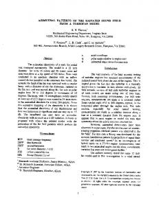
Figure 2: Schematic sketch of the algorithm in 2D. We assume that the original object, a vertical rectangle, has been deformed first by bending and then by an affine compression (the green arrow), as shown in (a). To recover the original shape, we identify corresponding point-pairs on the surface (b), and compute weighted centroid associated with each point-pair (shown as white dots in (c)). For each pair, we estimate a non-orthogonal coordinate frame from their local neighborhoods, as shown in (d). We compute the minimal stretch required to orthogonalize each local frame. After stretching, we rotate all of the local frames so that the estimated plane of symmetry is parallel to the y-axis. Finally, we integrate these local stretches and rotations in a global solve for the point-pairs on the output model. The rest of the surface is transformed using a thin-plate spline. (e) shows the result of our algorithm on the input point-pairs shown in (b).
2.2. Application:
3.1. Global symmetrization
Symmetrization has long been a subject of interest in paleontology (references date back to the 1840’s). The method we use for estimating the local symmetrizing affine transformation is a weighted version of a method recently proposed by Kazhdan et al. [KAG∗ 09] for symmetrizing an entire shape, which in turn is based on a well-known method in paleontology [ZPdL06]. These approaches “correct" for compression by stretching the fossil along the axis in which it appears to be compressed. This intentionally increases the volume while symmetrizing. A somewhat different closedform solution was proposed by Motani [Mot97]. Another recent method proposed in the paleontology literature also handles free-form bending as well as affine compression, using a series of optimizations [ONNI06]. This method again is based on minimizing the distance to the original points, so that large deformations would not be handled well. More constraints can be applied when multiple specimens are all deformed by a similar force (eg. many trilobites in a rock, multiple vertebrae from one specimen) [SS07].
The input to our second global optimization step is a set of 3-tuples, each encoding a bilateral symmetry on the two surface neighborhoods surrounding a point-pair. A tuple ((pi , qi ), ni , (M pi , Mqi )) includes the point-pair (pi , qi ), the normal ni of the local plane of mirror symmetry, and a pair of affine transformations (M pi , Mqi ) to be applied to the neighborhoods of pi and qi in order to approximate the local symmetry. For “standard" symmetrization, (M pi , Mqi ) approximate to identity.
3. Method We first describe the second step of our method, which combines local symmetries to do “standard" symmetrization. We then go on to discuss the computation of the two kinds of local transformations (stretching and rotation) in the two variants of the first step. In both cases we estimate the smallest transformation which establishes an approximate local symmetry. c 2010 The Author(s)
c 2010 The Eurographics Association and Blackwell Publishing Ltd. Journal compilation
The vector field formed by the ni must be consistently oriented; this is simple in our examples (we choose the normal closer to the negative x-axis), but for more difficult inputs a more sophisticated method (eg. [HDD∗ 92]) could be used. For each ni , we first compute a rotation matrix Qi , which takes ni to the negative x-axis. There are many possible such rotations; our heuristic is to choose the smallest one. Our goal now is to solve for new positions ri , si of the point-pairs, symmetric across the y − z plane, while keeping the vectors connecting neighboring points on the surface as similar as possible to the corresponding vectors on the transformed input. We express this by minimizing the following functional:
∑ ∑ φi, j [(ri − r j ) − QiM p (pi − p j )]2 i
i
j
+φi, j [(si − s j ) − Qi Mqi (qi − q j )]2 +αφi, j [(ri − s j ) − Qi (pi − q j )]2
D. Ghosh, N. Amenta & M. Kazhdan / EG Closed-form Blending of Local Symmetries
+αφi, j [(si − r j ) − Qi (qi − p j )]2
Weighted neighborhoods Pi , Qi around each pi , qi are defined by Gaussian weights θi, j , similar to the φi, j in Equation 1. To shorten notation we will write P, Q = Pi , Qi for the rest of this section.
with constraints:
ri,x = −si,x , ri,y = si,y , ri,z = si,z Here, φi, j are Gaussian weights on the connection between points i and j: (
φi, j = min e
−d 2 (pi −p j ) h2
,e
−d 2 (qi −q j ) h2
)
(1)
These weights define the neighborhoods around each of the pi , qi pairs based on the Euclidean distance, d(). We empirically select a different width h for each model, which is approximately 5 times the average distance between a landmark and its closest neighbor. The constant α is usually 0.01; the last two terms of the functional ensure that the two sides of the object are spaced apart from each other correctly. We omit M pi and Mqi from the last two normalization terms. In the application in which they are two different rotations, the vector (M pi pi − Mqi qi ) changes by an arbitrary translation, depending on where the center of rotation is chosen (notice that this is not an issue in the more important first two terms of the functional). We could choose the center of rotation so as to minimize the change in distance between pi and qi ; instead we use this simpler approximation of maintaining the original vector. We base the weights on the larger of the two distances d(pi , p j ), d(qi , q j ); this is again a heuristic. With inputs like the dragon in Figure 7 in mind, we assume the side with the larger distances is the “correct" one. The normal equations for this functional form three linear systems, for x, y and z. We substitute ri for si , according to the equality constraints. Solving these linear systems gives us the points ri . Finally, we use a thin-plane spline warp to move the rest of the mesh into the new symmetric position consistent with the placement of ri . 3.2. Local symmetries for affinely deformed models In the first step of our system, we compute the matrices M pi , Mqi for inputs which are deformed by compression as well as bending (eg. fossils). Within each local neighborhood, we want to estimate the smallest stretch that makes the resulting neighborhood locally symmetric. We use a the weighted version of the recent method of Kazhdan et al. [KAG∗ 09]. There are two steps: first we estimate a target plane H ∗ , which should be transformed into the plane of symmetry by our transformation, and then we compute the minimum stretch such that the neighborhood does indeed become symmetric across H ∗ .
To fit a target plane H ∗ to (P, Q), we use a “well-known" idea in symmetry detection [OO96]. A point set is isotropic if the principal components of its covariance matrix are all unit vectors. Consider a bilaterally symmetric point set P′ ∪ Q′ , and an affine transformation A such that (P, Q) = (AP′ , AQ′ ) is no longer bilaterally symmetric (ie. A includes a shear or non-uniform scale). An affine transformation T for which T P ∪ T Q is isotropic restores the bilateral symmetry (although in general (T P, T Q) 6= (P′ , Q′ )). We will find such a matrix T and then the best plane of symmetry H. The target plane of symmetry for (P, Q), back in the original space, is set to H ∗ = T −1 H. T can be computed from the weighted covariance matrix of P ∪ Q. Define t as the center of mass of P ∪ Q. The covariance matrix is C = ∑ θi, j ((p j − t)(p j − t)T + (q j − t)(q j − t)T )
(2)
j
We set T = C−1/2 , where C−1/2 is a matrix such that C C = C−1 ; such a matrix can be obtained by computing the SVD factorization of C and replacing the diagonal (eigenvalue) matrix with the diagonal matrix of the squareroots of the reciprocals. −1/2 −1/2
Next, we find the optimal plane of symmetry H with normal n for the bilaterally symmetric point set (T P, T Q), via weighted least-squares, as in [MGP07, ONNI06, KAG∗ 09]. Finally, we transform H and n back into the space of (P, Q), that is, we set H ∗ = T −1 H and n∗ = T −1 n. In general, H ∗ will not be orthogonal to n∗ (as in Figure 2), because T −1 reintroduces the non-homogeneous part of the affine transformation A. Now that we have H ∗ , we want to find a stretch that we can apply to the coordinate frame that will make n∗ perpendicular to H ∗ . There are many such symmetrizing stretches, so we seek the one with minimum stretching factor γ. The direction vector v of this minimal symmetrizing stretch lies in the plane spanned by n∗ and the normalized projection m of n∗ onto H ∗ :
v = (n∗ − m)/2 γ = tan(β/2) where β is the angle between vectors n∗ , −m. Let Si be the matrix that expresses this stretch. In the global step we set (M pi , Mqi ) = (Si , Si ), that is, we apply Si to both sides in the same way to achieve approximate bilateral symmetry, and we set ni = Si n∗ , the normal of the plane of symmetry after the stretch. c 2010 The Author(s)
c 2010 The Eurographics Association and Blackwell Publishing Ltd. Journal compilation
D. Ghosh, N. Amenta & M. Kazhdan / EG Closed-form Blending of Local Symmetries
3.3. Local symmetries in articulated models An articulated model has joints, which can bend or rotate, so that neighborhoods on corresponding parts of the model that are symmetric when the model is in a symmetric pose (eg. a person’s two hands) are not bilaterally symmetric in an arbitrary pose. For each neighborhood (Pi , Qi ), we find the rotation Zi with minimal angle, such that using (M pi , Mqi ) = (Zi−1 , Zi ) makes P and Q bilaterally symmetric. The translation of the two neighborhoods is handled by the global symmetrization in Step 2. We begin by translating the two point sets Pi , Qi so that their two centroids are both located at the origin; note that rotation and reflection are commutative on a point-set centered at the origin. We would like to solve for the rotation R and reflection U minimizing:
∑ kpi −URqi k2 . i
Denoting by A the antipodal map, A(p) = −p, we have:
∑ kpi −URqi k2 = ∑ kpi − (AU)RA(qi )k2 .
Figure 3: Point-pairs are place on our input models using the interactive Landmark software. The input points do not need to be dense, nor do they need to be uniformly spaced. The symmetrized result (just Step 2) is on the right.
R = DV is a rotation around a of angle γ = θ − π. Denoting Zi to be a rotation by angle γ/2 about a, we set (M pi , Mqi ) = (ZiT , Zi ), and ni to be the normal to the plane of reflection associated with U. 4. Results
i
i
4.1. Input generation If we set V to be the rotation V = (AU)R, we get:
∑ kpi −URqik2 = ∑ kpi −V (Aqi )k2 . i
i
We can solve for this rotation V that optimizes the alignment error between the sets pi and Aqi (eg. using Horn’s algorithm [Hor87]). Although V is unique, it does not mean that there is only one rotation R which optimizes bilateral symmetry. If we set D to be a rotation by 180 degrees about any axis, then setting U = AD and setting R = DV , we get:
∑ kpi −V (Aqi )k2 i
=
∑ kpi − AADDV (Aqi )k2
We take as input a set of point-pairs which are intended to be symmetric on the output surface. In our examples we indicated these input correspondences interactively, using our Landmark software, which was designed for this purpose [WAA∗ 05]. Landmark allows us to efficiently indicate dense correspondences along curves and patches defined by a small set of user placed points, as shown in Figure 3. Because we interactively generate correspondences, we can use imperfect meshes that have holes, and may not be manifolds; this is important in applications. Fossils are also often broken or deformed in ways which make automatic symmetry detection difficult even when given a clean mesh. Interaction also gives an expert the freedom to indicate features that might not be evident in a digitized fossil, but are visible on the original specimen or are characteristic of its species.
i
=
∑ kpi − AUR(Aqi )k2 i
=
2
∑ kpi −URqi k i
That is, for any choice of D, we can find a rotation R and a reflection U minimizing the symmetry error. Again, we would like to choose D so that R = DV is as close to the identity as possible (i.e. so that we rotate the points qi as little as possible to align them with the pi ). V is a rotation by an angle of 0 ≤ θ ≤ π about some axis a. So D should also be chosen as a rotation about a, and the minimal rotation c 2010 The Author(s)
c 2010 The Eurographics Association and Blackwell Publishing Ltd. Journal compilation
4.2. Results Symmetrizing two-dimensional data sets has been a topic of interest in paleontology for more than 150 years, and trilobites like the one in Figure 4 are a classic test case [Sal64, CAC05]. Based on the assumption that the fossil underwent an affine compression, the symmetrization stretches the object, intentionally increasing the area. We have applied our combined affine stretching and straightening method to digitized 3D models of several fossil crania. Crania are particularly important in studies of primate evolution, including the evolution of hominids like ourselves. The model in Figure 1 is from a cast of the Homo
D. Ghosh, N. Amenta & M. Kazhdan / EG Closed-form Blending of Local Symmetries
Figure 4: Stretching the image of a trilobite to restore symmetry, a classic example from paleontology. Many specie of trilobites flourished during the Paleozoic era; they are distinguished by the shapes of their fossilized exoskeletons. Figure 6: Result (right) of symmetrization of an articulated object
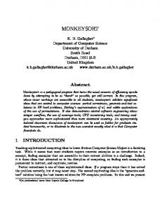
Figure 5: Both affine stretching and bending are necessary to approximately symmetrize this three-dimensional cranium of Paradolichopithecus, an extinct Old World monkey. The pattern in which the more rigid jaw is bent with respect to the flattened back of the skull is typical of fossil crania.
habilis ER 1813 fossil, a possible human ancestor. The apparent compression in the fossil is removed by the stretching in Step 1 of our method. Figure 5 shows the symmetrization of a fossil monkey skull from below, showing a typical pattern of distortion which is also evident in the Homo habilis cranium. We are able to symmetrize articulated models as shown in Figures 1, and 6. In Figures 3, 7, 8 we present results on models that are locally bent. Treating them as articulated models, Mi approximates the identity. We compare one of our results with that of Mitra et al. [MGP07] in Figure 7, observing very similar results. Both seem shorter than one would expect, as the dragon does not lengthen while unwinding. We believe that both our user-indicated local symmetries and the automatically detected local symmetries fail to capture the “true" local symmetries near the sharp curves.
Figure 7: The result of Mitra et al. is on the left, the input at the center, with our symmetrized result to the right.
Finally, we use our method to fill in missing or erroneous regions. This is important in paleontology, as illustrated by the example in Figure 9. We interactively attached the missing left canine using a mesh editing tool, to provide an approximate mesh for the large missing feature. We then symmetrize the model using our system, giving the canine on the correct right side a weight of one and the canine on the left a weight of zero. The landmark pair weights, α is also set to zero for missing regions. Using the symmetrization step alone, we removed the broken region near the chin of the Igea model in Figure 8. 5. Limitations and discussion Table 1 shows the computation time in seconds, measured on an Intel dual-core 2.4GHz with 2GB RAM. These timings do not include interactively indicating point-pair correspondences. Even using the Landmark interface, this is time consuming. Automatic detection of symmetric correspondences would make this easier, although in paleontolc 2010 The Author(s)
c 2010 The Eurographics Association and Blackwell Publishing Ltd. Journal compilation
D. Ghosh, N. Amenta & M. Kazhdan / EG Closed-form Blending of Local Symmetries
Figure 10: Results of using different number of correspondences. (a) is the asymmetric input pose. Results of symmetrization using 22 (b), 265 (c) and 606 (d) point correspondences.
Table 1: Table showing the time taken to symmetrize, after placing the required set of point-pairs on a model. The number of user-placed points on one side of the model is shown in the second column, and the number of automatically generated points (based on user-placed curves and patches) is in the third.
Figure 8: Figure on the right shows Igea after symmetrization. Our technique is able to fix the broken region on her chin, by indicating the broken region as “missing", and using the symmetrized points from the other side.
Figure 9: Left shows a scan of a cast of Victoriapithecus macinnesi, the oldest known cranium of an Old World Monkey. We symmetrize the model, and add the missing fang, by first using a mesh editing tool to add a fang, and then symmetrizing it with the one that is present (right).
ogy and archeology applications it would still be important to retain the option of user interaction at every step. Symmetry detection methods in computer graphics so far have not addressed the automatic detection of bilateral symmetries masked by non-uniform affine transformations. In computer vision, however, the detection of the symmetries of 3D objects in perspective images leads to a very similar problem, and there is a well-developed literature on so-called skewsymmetries [VGMP96]. c 2010 The Author(s)
c 2010 The Eurographics Association and Blackwell Publishing Ltd. Journal compilation
Model Bunny Igea Dragon Hominid Paradol Vic Ben Armadillo WoodDoll
User-placed 60 69 183 72 106 95 161 181 115
Auto 130 191 761 448 616 148 774 425 252
Time (in secs) 6.61 7.6 173.5 38.5 90.8 8.41 109.48 63.45 18.4
Our method includes the heuristic choice of the Qi as the smallest rotations taking each local plane of symmetry to the vertical plane. A method with no heuristics, so that the result would be guaranteed to minimize deformation, would be more satisfying. Simultaneously minimizing the Qi and the the positions (ri , si ) would have to be formulated as a non-linear problem, as far as we can see, which might have local optima. An alternative research direction might be to find better a better heuristic. There are three weighting parameters, the standard deviations of the Gaussian weight functions φ and θ, and the parameter α controlling the weight of connections between the pi and qi . These can be set so as to produce incorrect results. In particular, when φ is too large the distances between points which are not adjacent on the surface are preserved, so that bent models are shortened by the symmetrization. But φ also has to be large enough so that neighboring points are connected. In Figure 10 we reduce the number of correspondences, so that φ has to be increased to maintain connectivity. When the number of correspondences becomes very small, the result is shrunken and the shape is not well-preserved. A
D. Ghosh, N. Amenta & M. Kazhdan / EG Closed-form Blending of Local Symmetries
better way of reflecting the shape using a weighted graph on surface samples would allow sparser sampling. We currently assume that any non-homogeneous affine deformation is due to compression. A volume-preserving assumption might be a better choice in other applications. Our overall framework might also be applied to morphing between differently-shaped objects and to animating articulated models by generating intermediate poses. 6. Acknowledgements This work is funded by the National Science Foundation grants SEI(SPE)-0513894 and CCF-0635250. We thank Eric Delson, Will Harcourt-Smith, Karen Baab and the NYCEP Morphometrics group for the scanned fossil crania skulls, and the Stanford 3D Scanning Repository and AIM@SHAPE Repository for all the other 3D data. We especially thank Dan A. Alcantara for help with the 2D TPS implementation and images. References [Ata85] ATALLAH M. J.: On symmetry detection. IEEE Trans. Comput. 34, 7 (1985), 663–666. 1 [BBW∗ 09] B OKELOH M., B ERNER A., WAND M., S EIDEL H.P., S CHILLING A.: Symmetry detection using feature lines. In Proceedings of Eurographics (2009). 1 [CAC05] C RÔNIER C., AUFFRAY J.-C., C OURVILLE P.: A quantitative comparison of the ontogeny of two closely-related upper devonian phacopid trilobites. Lethia 38 (2005), 123–135. 5 [GPF09] G OLOVINSKIY A., P ODOLAK J., F UNKHOUSER T.: Symmetry-aware mesh processing. In Proceedings of the 13th IMA International Conference on Mathematics of Surfaces XIII (Berlin, Heidelberg, 2009), Springer-Verlag, pp. 170–188. 1, 2 [HDD∗ 92] H OPPE H., D E ROSE T., D UCHAMP T., M C D ONALD J., S TUETZLE W.: Surface reconstruction from unorganized points. In Computer Graphics (1992), SIGGRAPH 1992 Proceedings, pp. 71–78. 3 [Hor87] H ORN B.: Closed-form solution of absolute orientation using unit quaternions. Journal of the Optical Society A 4, 4 (April 1987), 629–642. 5 [KAG∗ 09] K AZHDAN M., A MENTA N., G U S., W ILEY D. F., H AMANN B.: Symmetry restoration by stretching. In Canadian Conference on Computational Geometry (2009). See preprint at http.www.cs.ucdavis.edu/∼amenta/pubs/pubs.html. 2, 3, 4
[Mot97] M OTANI R.: New technique for retrodeforming tectonically deformed fossils, with an example for ichthyosaurian specimens. Lethaia 30 (1997), 221–228. 3 [MSHS06] M ARTINET A., S OLER C., H OLZSCHUCH N., S IL LION F. X.: Accurate detection of symmetries in 3d shapes. ACM Trans. Graph. 25, 2 (2006), 439–464. 1 [ONNI06] O GIHARA N., N AKATSUKASA M., N AKANO Y., I SHIDA H.: Computerized restoration of nonhomogeneous deformation of a fossil cranium based on bilateral symmetry. Americal Journal of Physical Anthropology 130 (2006), 1–9. 3, 4 [OO96] O’M ARA D., O WENS R.: Measuring bilateral symmetry in digital images. In Procs. of TENCON ’96 (November 1996), pp. 151–156. 4 [PMG∗ 05] PAULY M., M ITRA N. J., G IESEN J., G ROSS M., G UIBAS L. J.: Example-based 3d scan completion. In SGP ’05: Proceedings of the third Eurographics symposium on Geometry processing (Aire-la-Ville, Switzerland, Switzerland, 2005), Eurographics Association, p. 23. 2 [PMW∗ 08] PAULY M., M ITRA N. J., WALLNER J., P OTTMANN H., G UIBAS L. J.: Discovering structural regularity in 3d geometry. ACM Trans. Graph. 27, 3 (2008), 1–11. 1 [PSG∗ 06] P ODOLAK J., S HILANE P., G OLOVINSKIY A., RUSINKIEWICZ S., F UNKHOUSER T.: A planar-reflective symmetry transform for 3d shapes. ACM Trans. Graph. 25, 3 (2006), 549–559. 1 [RBBR10] R AVIV D., B RONSTEIN A., B RONSTEIN M., R.K IMMEL: Full and partial symmetries of non-rigid shapes. International Journal of Computer Vision 89, 1 (2010), 18–39. 1 [Sal64] S ALTER J. W.: Figures and descriptions illustrative of British organic remains. Decade XI. Trilobites (chiefly Silurian). Memoirs of the Geological Survey of the United Kingdom, 1864. 5 [SKS06] S IMARI P., K ALOGERAKIS E., S INGH K.: Folding meshes: hierarchical mesh segmentation based on planar symmetry. In SGP ’06: Proceedings of the fourth Eurographics symposium on Geometry processing (Aire-la-Ville, Switzerland, Switzerland, 2006), Eurographics Association, pp. 111–119. 1 [SS97] S UN C., S HERRAH J.: 3d symmetry detection using the extended gaussian image. IEEE Trans. Pattern Anal. Mach. Intell. 19, 2 (1997), 164–168. 1 [SS07] S HAH J., S RIVASTAVA D. C.: Strain estimation from distorted vertebrate fossils: application of the wellman method. Geological Magazine 144, 01 (2007), 211–216. 3 [VGMP96] VAN G OOL L., M OONS T., P ROESMANS M.: Mirror and point symmetry under perspective skewing. In Computer Vision and Pattern Recognition, 1996. Proceedings CVPR ’96, 1996 IEEE Computer Society Conference on (Jun 1996), pp. 285–292. 7
[KCD∗ 03] K AZHDAN M., C HAZELLE B., D OBKIN D., F UNKHOUSER T., RUSINKIEWICZ S.: A reflective symmetry descriptor for 3d models. Algorithmica (October 2003), 201–225. 1
[WAA∗ 05] W ILEY D. F., A MENTA N., A LCANTARA D. A., G HOSH D., K IL Y. J., D ELSON E., H ARCOURT-S MITH W., ROHLF F. J., J OHN K. S., H AMANN B.: Evolutionary morphing. In Proceedings of IEEE Visualization (2005), pp. 431–438. 5
[LSLCO05] L IPMAN Y., S ORKINE O., L EVIN D., C OHEN -O R D.: Linear rotation-invariant coordinates for meshes. ACM Trans. Graph. 24, 3 (2005), 479–487. 2
[XZT∗ 09] X U K., Z HANG H., TAGLIASACCHI A., L IU L., L I G., M ENG M., X IONG Y.: Partial intrinsic reflectional symmetry of 3d shapes. ACM Trans. Graph. 28, 5 (2009), 1–10. 1
[MGP06] M ITRA N. J., G UIBAS L. J., PAULY M.: Partial and approximate symmetry detection for 3d geometry. ACM Trans. Graph. 25, 3 (2006), 560–568. 1
[ZPA95] Z ABRODSKY H., P ELEG S., AVNIR D.: Symmetry as a continuous feature. IEEE Trans. Pattern Anal. Mach. Intell. 17, 12 (1995), 1154–1166. 1
[MGP07] M ITRA N. J., G UIBAS L. J., PAULY M.: Symmetrization. In SIGGRAPH ’07: ACM SIGGRAPH 2007 papers (New York, NY, USA, 2007), ACM, p. 63. 1, 2, 4, 6
[ZPdL06] Z OLLIKOFER C. P. E., P ONCE DE L EÓN M. S.: Virtual Reconstruction: A Primer in Computer-assisted Paleontology and Biomedicine. New York: Wiley, 2006. 3
c 2010 The Author(s)
c 2010 The Eurographics Association and Blackwell Publishing Ltd. Journal compilation