CNC-Simulator Turning with Driven Tools and Counter Spindle. Programmer's
Guide. Version 6.07. Mathematisch Technische Software - Entwicklung GmbH.
CNC-Simulator Turning with Driven Tools and Counter Spindle
Programmer's Guide
Version 6.07
Mathematisch Technische Software - Entwicklung GmbH Kaiserin-Augusta-Allee 101 D 10553 Berlin ( +49 / 30 / 34 99 600
Programmer's Guide CNC Simulator for Turning Version6.7 © MTS Mathematisch Technische Software-Entwicklung GmbH Kaiserin-Augusta-Allee 101 D-10553 Berlin ( + 49 / 30 / 34 99 600 Fax +49 / 30 / 34 99 60 25 eMail:
[email protected] WWW: http://www:mts-cnc.com Berlin, May 1995ofp, June 1998 akss, ofp, July 1998 BM; All rights reserved, including photomechanical reproduction and storage on electronic media.
DIN (Deutsche Industrie Norm), is the German Standard Specification as defined by the "Deutsches Institut für Normung e. V." MS-DOS is a trademark of Microsoft Corporation PAL is short for "Prüfungs- Aufgaben und Lehrmittelentwicklungsstelle" (Institute for the Development of Examination Standards and Training Aids), a division of the "IHK Mittlerer Neckar" (Chamber of Industry and Commerce of the Middle-Neckar Region)
Contents
Table of Contents 0 Introduction.....................................................................................................................9 0.1 CNC Simulator Turning with Driven Tools and Counter Spindle ...........................................................10 0.2 Changes and Supplements to the Version 5.x ......................................................................................11
1 Basic Geometry ............................................................................................................13 1.1 The Coordinate System .........................................................................................................................13 1.2 Reference Points ...................................................................................................................................15 1.3 Absolute Dimensioning, Incremental Dimensioning ..............................................................................17 1.4 Tool Geometry.......................................................................................................................................19 1.4.1 Compensation Value Storage .......................................................................................................21 1.4.2 Tool Nose Compensation TNC .....................................................................................................23
2 Introduction into NC Programming.............................................................................25 2.1 Structure of an NC Block (Format) ........................................................................................................25 2.2 Modal Commands and Non-modal Commands ....................................................................................26 2.3 Application and Representation of Addresses.......................................................................................27
3 Miscellaneous Functions (M-Functions) .................................................................... 28 3.1 Activate/Deactivate Spindle ...................................................................................................................28 3.2 Coolant ..................................................................................................................................................28 3.3 Programmed Halt ..................................................................................................................................28 3.4 Program End .........................................................................................................................................29 3.5 Lock / Unlock Centre Sleeve .................................................................................................................29 3.6 Feedrate ................................................................................................................................................29 3.7 Spindle Speed .......................................................................................................................................29 3.8 Tool Change ..........................................................................................................................................30
4 Programming Commands in Compliance with DIN 66025 ........................................31 4.1 Rapid Traverse G00 ..............................................................................................................................33 4.2 Linear Interpolation in Slow Feed Motion G01.......................................................................................35 4.3 Clockwise Circular Interpolation G02 ....................................................................................................36 4.4 Circular Interpolation Counter-Clockwise G03 ......................................................................................37 4.5 Dwell G04 ..............................................................................................................................................38 4.6 polygonal machining G08 ......................................................................................................................38 4.7 In-Position Programming (Deceleration) G09 .......................................................................................39 4.8 Inch Data Input G20 ..............................................................................................................................40 4.9 Metric Data Input (mm) G21..................................................................................................................41 © MTS GmbH 1998
3
Contents 4.10 Invocation of a Subprogram G22........................................................................................................ 43 4.11 Repeated Program Parts G23 ............................................................................................................ 44 4.12 Unconditional Jump G24..................................................................................................................... 45 4.13 Move to the Reference Point G25....................................................................................................... 46 4.14 Move to the Tool-Changing Position G26 ........................................................................................... 47 4.15 Positioning the Tailstock G28 ............................................................................................................. 48 4.16 Thread Cutting G33 (Chasing Cycle).................................................................................................. 50 4.17 Tool Nose Compensation G41 / G42.................................................................................................. 52 4.18 Cancel Tool Nose Compensation G40 ............................................................................................... 52 4.19 In Rapid Travel Movement to the Target Position G48....................................................................... 53 4.20 Description of a Final Contour G51..................................................................................................... 55 4.21 Define Workpiece Zero - Absolute: G54 - G56 and G58.................................................................... 57 4.22 Incremental Zero Shift G59................................................................................................................. 59 4.23 Cancel Incremental Zero Shift G53 .................................................................................................... 60 4.24 Activate Absolute Dimensions G90..................................................................................................... 61 4.25 Activate Incremental Dimensions G91................................................................................................ 62 4.26 Spindle Speed Limitation G92 ............................................................................................................ 63 4.27 Feedrate (Millimeters per Minute) G94 ............................................................................................... 64 4.28 Feedrate (Millimeters per Revolution) G95......................................................................................... 65 4.29 Constant Cutting Speed G96 .............................................................................................................. 66 4.30 Cancel Constant Cutting Speed G97.................................................................................................. 66
5 Cycles ............................................................................................................................67 5.1 Complete Table of Available Cycles ..................................................................................................... 67 5.2 Threading Cycle G31 ............................................................................................................................ 69 5.3 Travel Range Limitation G36 for Multipass Cycles ............................................................................... 72 5.4 Finishing Allowance G57 ...................................................................................................................... 73 5.5 Straight Roughing Cycle / Rectangular Contour G75 ........................................................................... 77 5.6 Cross Roughing Cycle / Rectangular Contour G76 .............................................................................. 79 5.7 Clearance Cutting Cycle: G78 .............................................................................................................. 81 5.8 Thread Undercut G78 in Compliance with DIN 76................................................................................ 85 5.9 Recessing Cycle with chamfers, roundings and bevelled sides G79 ................................................... 87 5.10 Straight Roughing Cycle for any Contour G81 .................................................................................... 88 5.11 Cross Roughing Cycle with any Contour G82..................................................................................... 98 5.12 Processing Cycle (Last Specified Cycle) G80 .................................................................................. 107 5.13 Contouring Cycle/Multipass Cycle G83............................................................................................. 111 5.14 Travel Range Limitation for Multipass Cycles G36 ........................................................................... 113 5.15 Deep Drilling Cycle G84.................................................................................................................... 115 5.16 Clearance Cutting Cycle G85 ........................................................................................................... 117 5.17 Thread Undercut in Compliance with DIN 76 ................................................................................... 121 5.18 Recessing Cycle for rectangular recesses G86................................................................................ 123
4
Programmer's Guide for CNC Turning, Version 6.07
Contents 5.19 Recessing Cycle for any Contour G87 ..............................................................................................124 5.20 Radius/Chamfer Cycle G88...............................................................................................................131 5.21 Straight/Plane Roughing Cycle (conical contour) G89 ......................................................................135
6 Segment Contour Programming ...............................................................................142 6.1 G-Functions for Contour String Programming.....................................................................................142 6.2 Additional Addresses ...........................................................................................................................146 6.2.1 Circle Centres Absolute...............................................................................................................147 6.2.2 Tangential Transitions .................................................................................................................148 6.2.3 Selection of Solutions ..................................................................................................................151 6.3 Rounding between Two Entities ..........................................................................................................157 6.3.1 Chamfer between Two Lines.......................................................................................................159 6.4 Two-Point String: Straight Line G71 ....................................................................................................160 6.5 Two-Point String: Arc G72/G73 ..........................................................................................................162 6.6 Three-Point String: Line - Line G71G71 .............................................................................................166 6.7 Three-Point String: Arc - Line G72G71 or G73G71 ............................................................................170 6.8 Three-Point String: Line - Arc G71G72 or G71G73 ...........................................................................176 6.9 Three-Point String: Arc - Arc G72G72 or G72G73 or G73G72 or G73G73 ........................................183 6.10 Four-Point String:with Tangential Transitions....................................................................................188 6.11 Open Contour Strings........................................................................................................................194 6.12 Tangential Connection.......................................................................................................................201
7 Parameters ..................................................................................................................205 8 Programming with Special Characters..................................................................... 207 8.1 Comments ...........................................................................................................................................207 8.2 Skipping of NC blocks .........................................................................................................................207 8.3 Temporary Free Format ......................................................................................................................209 8.4 Arithmetic Operations ..........................................................................................................................209 8.5 Example of Programming with Parameters and Arithmetic Operations ..............................................213
9 Setup Form..................................................................................................................215 9.1 Preface ................................................................................................................................................215 9.2 Syntax of the Setup Form....................................................................................................................217 9.3 Setup Data: Beginning/End Indicator...................................................................................................218 9.4 Setup Data: Configuration Files...........................................................................................................218 9.5 Setup Data: Blank................................................................................................................................219 9.6 Setup Data: Prefabricated Part............................................................................................................221 9.7 Setup Data: Clamping Devices............................................................................................................222 9.8 Setup Data: Clamping Mode ...............................................................................................................223 9.9 Setup Data: Tailstock/Sleeve ..............................................................................................................224 9.10 Setup Data: Chucking Depth .............................................................................................................224 © MTS GmbH 1998
5
Contents 9.11 Setup Data: Counter Spindle ............................................................................................................ 225 9.12 Setup Data: Current Tool .................................................................................................................. 226 9.13 Setup Data: Tools in the Turret......................................................................................................... 226 9.14 Setup Data: Driven Tools.................................................................................................................. 227 9.15 Setup Data: Compensation Values................................................................................................... 230
10 NC Program Analysis ...............................................................................................231 11 3D-View .....................................................................................................................233 12 CNC-Turning with the Counter Spindle .................................................................. 235 12.1 Preface.............................................................................................................................................. 235 12.2 Configuration..................................................................................................................................... 237 12.3 Programming the Counter Spindle ................................................................................................... 238 12.3.1 Machining Transfer to the Main Spindle G29 ........................................................................... 238 12.3.2 Work Part Transfer G30 ........................................................................................................... 239 12.3.3 Incremental Shift of the Counter Spindle Reference Point (when Programming Travel Movements) G59 ................................................................................................................................. 240 12.3.4 Travel Movement of the Counter Spindle in Rapid Speed Movement G00.............................. 241 12.3.5 Travel Movement of the Counter Spindle with Infeed F in mm/min G01.................................. 242 12.3.6 Counter Spindle to the Counter Spindle Reference Point G27................................................. 243 12.3.7 Switching on Machining on the Counter Spindle G28............................................................... 244 12.3.8 Bar feed for work parts in the main spindle G05 ...................................................................... 246
13 CNC Turning with Driven Tools...............................................................................247 13.1 Preface.............................................................................................................................................. 247 13.2 Configuration..................................................................................................................................... 251 13.3 Turning Plane G14............................................................................................................................ 252 13.4 Standard Plane G15 ......................................................................................................................... 253 13.5 Free-definable Plane G16................................................................................................................. 254 13.6 Programming the Selection of the Free-definable Plane G16 .......................................................... 259 13.7 Machining Cycles in the Free-definable Plane G16 .......................................................................... 262 13.7.1 Face Milling Cycle G60 ............................................................................................................. 262 13.7.2 Drilling Cycle G61 ..................................................................................................................... 264 13.7.3 Thread Tapping G62................................................................................................................. 265 13.7.4 Reaming/Boring G63 ................................................................................................................ 266 13.7.5 Square Pocket/Groove G64...................................................................................................... 267 13.7.6 Circular Pocket G65.................................................................................................................. 268 13.7.7 Tapping G66 ............................................................................................................................. 269 13.8 Multiple Cycles in the Free-definable Plane G16 .............................................................................. 270 13.8.1 Cycle on a Circle G67 ............................................................................................................... 270 13.8.2 Cycle on a Radius G68 ............................................................................................................. 271 13.8.3 Cycle at a Point G69 ................................................................................................................. 272 13.9 Front Face G17................................................................................................................................. 273 13.9.1 Rapid Speed Movement in Polar Coordinates G10.................................................................. 274 13.9.2 Linear Interpolation in Polar Coordinates G11.......................................................................... 275 13.9.3 Circle Interpolation in Polar Coordinates Clockwise G12 ......................................................... 276 13.9.4 Circle Interpolation in Polar Coordinates Counterclockwise G13 ............................................. 277 13.10 Machining Cycles in the Front Face G17 ........................................................................................ 278
6
Programmer's Guide for CNC Turning, Version 6.07
Contents 13.10.1 Drilling Cycle G61 ....................................................................................................................278 13.10.2 Thread Cutting G62.................................................................................................................279 13.10.3 Reaming/Boring G63 ...............................................................................................................280 13.10.4 Square Pocket/Groove G64 ....................................................................................................281 13.10.5 Circular Pocket G65 ................................................................................................................282 13.10.6 Tapping G66............................................................................................................................283 13.11 Multiple Cycles in the Front Face G17.............................................................................................284 13.11.1 Cycle on a Circle G67..............................................................................................................284 13.11.2 Cycle on a Radius G68............................................................................................................285 13.11.3 Cycle at a Point G69................................................................................................................286 13.12 Shell Surface - G18 .........................................................................................................................287 13.12.1 Rapid Speed Movement in Cylinder Coordinates G10 ............................................................289 13.12.2 Interpolation of Straight Lines in Cylinder Coordinates G11....................................................290 13.12.3 Circle Interpolation in Cylinder Coordinates Clockwise G12 ...................................................291 13.12.4 Circle Interpolation in Polar Coordinates Counterclockwise G13 ............................................292 13.13 Machining Cycles in the Shell Surface G18.....................................................................................293 13.13.1 Drilling cycle G61.....................................................................................................................293 13.13.2 Thread Cutting G62.................................................................................................................294 13.13.3 Reaming/Boring G63 ...............................................................................................................295 13.13.4 Square Pocket/Groove G64 ....................................................................................................296 13.13.5 Circular Pocket G65 ................................................................................................................297 13.13.6 Tapping G66............................................................................................................................298 13.14 Multiple Cycles in the Shell Surface G18.........................................................................................299 13.14.1 Cycle on a Circle G67..............................................................................................................299 13.14.2 Cycle on a Radius G68............................................................................................................300 13.14.3 Cycle at a Point G69................................................................................................................301 13.15 Chord Surface G19..........................................................................................................................302 13.16 Machining Cycles in the Chord Surface G19...................................................................................304 13.16.1 Plane Milling Cycle G60...........................................................................................................304 13.16.2 Drilling Cycle G61 ....................................................................................................................306 13.16.3 Thread Cutting G62.................................................................................................................307 13.16.4 Reaming/Boring G63 ...............................................................................................................308 13.16.5 Square Pocket/Groove G64 ....................................................................................................309 13.16.6 Circular Pocket G65 ................................................................................................................310 13.16.7 Tapping G66............................................................................................................................311 13.17 Multiple Cycles in the Chord Face ...................................................................................................312 13.17.1 Cycle on a Circle G67..............................................................................................................312 13.17.2 Cycle on a Radius G68............................................................................................................313 13.17.3 Cycle at a Point G69................................................................................................................314
Appendix : Table of Programmable Addresses ..........................................................315 Index ...........................................................................................................................................................318
© MTS GmbH 1998
7
Introduction
0 Introduction Dear user of the MTS CNC Simulator Turning 6, To make CNC Software for training and production means for us to follow carefully the development of CNC machines and controls all the time. With the target to give you an up-to-date product for the CNC programming of machining processes with five controllable NC axes, driven tools and counter spindle the MTS CNC Simulator is being constantly further developed and updated. These further developments are released as a new software version with corresponding modifications of operating and programming manuals. MTS Mathematisch Technische Software-Entwicklung GmbH
Regarding this edition This Programmer's Guide explains all available NC commands of the MTS Programming Code. In addition to the DIN 66025 commands, the programming of machining cycles and segment contour programming are explained. The MTS Programming Code is non-proprietary, i.e. not any specific to any one manufacturer's CNC control system. The Programmer's Guide is structured as follows: This Programmer's Guide explains all available NC commands of the MTS Programming Code. In addition to the DIN 66025 commands, the programming of machining cycles, segment contour programming, the programming of the counter spindle and driven tools are explained. The MTS Programming Code is non-proprietary, i.e. not any specific to any one manufacturer's CNC control system. The Programmer's Guide is structured as follows: Part One presents and explains the basic techniques of NC programming. Part Two, which is far more extensive, explains all commands which are part of the MTS programming code. For reasons of clarity these have been arranged in three main sections: -
DIN Commands Machining Cycles Segment Contour Programming (Contour Strings) Counter Spindle Driven Tools
This structure is intended to provide an easy introduction to NC programming even for the unskilled user. The expert programmer may use the clearly structured listing of commands as a quick-reference manual when confronted with complicated tasks. The general idea of the Programmer's Guide is to provide the user with explanations and support as he becomes familiar with manual programming. All mandatory and optional parameters are explained using NC Blocks and graphically represented.
© MTS GmbH 1998
9
Introduction
0.1 CNC Simulator Turning with Driven Tools and Counter Spindle Complete Machining
The re-developed version 6 of the CNC system turning expands the performance of the MTS CNC Simulator. In addition to improved programming of rotation symmetrical machining it is possible to create and simulate easily NC programs for complete machining with driven tools and a counter spindle. Both of the new modules are optionally available to the new basic version of CNC Turning 6.
5 Controllable NC Axis: X, Z, C, Y, B
For the realization of complex machining tasks 5 controllable NC axes and driven tools are available. It is possible to position the C axis exactly and to interpolate it, for instance, to generate geometries by overlaying tool movements. The turret can additionally be moved in the Y axis and rotated in the B axis.
Counter Spindle
To support rear side machining a special free-configurable counter spindle has been realized on a track of its own for the work part take-over. Counter spindle and turret can be configured alternatively. For machining on counter spindle a complete programming code including the application of driven tools is available.
2D- and 3D-Representation in Multiple Windows Technique
The dynamic simulation of machining with driven tools is carried out in the CNC Simulator Turning in multiple windows technique enabling both 2D as well as 3D representations of the machining process. Hereby the contour of the work part being machined is being constantly updated.
Screen Layout in CNC Simulator 6 Turning during Machining with Driven Tools
When machining with driven tools the following four windows are represented on the screen: 1
2
3
4
1 Longitudinal section as a full section on X, Z plane based on the current C axis (so-called C cut). The view can be shifted and zoomed as desired. The window 2 is always represented in the same scale as the window 1. 2 Section cut as a full section on X, Y plane. The Z coordinate of the section can be selected in window 1. 3 Free-definable view of a work part or of the whole work space of the CNC turning machine corresponding to window 1. 4 3D machining view. Distance and viewing angle in relation to the work space can be changed as desired.
10
Programmer's Guide for CNC Turning, Version 6.07
Introduction
3D-Collision Monitoring
During machining processes with driven tools collision monitoring is carried out in 3D window. It considers the clamping device, the non-cutting parts of the tool (shaft, take-over, turret) as well as the cutting part of the tool during rapid speed movement of the tool.
NC Data Analysis
The CNC Simulator Turning 6 offers as an effective function the possibility to acquire production-relevant technology information during the simulation of an NC program. In the programming analysis of rotation-symmetrical machining the work phases are represented as machining paths for each tool and the corresponding technology data is acquired. After the analysis the following data referring to the work phases is available as a table: machining diameter area, RPM, cutting speed, feed-in, path, feed-in rate, rapid transfer speed, tool change time, cut volume, cut mass. The analyzed data can be stored in the current NC program where it is correspondingly available for further evaluation.
0.2 Changes and Supplements to the Version 5.x Change of Address Letter
Due to the application of the address letter C for the programming of the C axis it was necessary to change the address letters. Old: C (Chamfer, Radius) R (Parameter identification letter) P (Block number, alternative)
New:
ð
R
Address letter for programming of chamfers and radii
ð
P
Address letter for programming of parameters
ð
O
Address letter for programming of block numbers and choice of alternatives
C
Positionable turning axis
Y
Additional feed axis for the turret
B
Additional swivel rotation axis for the turret (depending on machine configuration and of the current machining plane) Exception: During contour programming of G72/G73 B remains circle radius.
Summary of some G-commands
When uniforming MTS syntax some of the commands were put together: The previous cycles G87 (radius) and G88 (chamfer) were put together to G88. This cycle can generate both radii and chamfers. The previous cycles G65 (straight roughing cycle, conical contour) and G66 (plane roughing cycle, conical contour) are replaced by the cycle G89.
Some new G commands as syntax extension
© MTS GmbH 1998
To extend the performance of MTS syntax for the NC programming of rotationsymmetrical machining additional addresses were included in some G commands. The parameters of the cycles G81 (straight roughing cycle of any contour) and G82 (plane roughing cycle of any contour) were extended. The parameters E, A, O and Q have been added.
11
1. Basic Geometry
Examples
Diagram 1.1 :
P :
X= 20, Y= 30
P :
X=-20, Y= 15
P :
X= 40, Y=-25
Cartesian Coordinate System
Angles of holes on a divided circle Diagram 1.2
Determination of a point by the length L and the angle A Diagram 1.3
Two-dimensional coordinate system for NC programming for turning Diagram 1.4
12
Programmer's Guide for CNC Turning, Version 6.07
1.1 Coordinate System
1 Basic Geometry In this chapter we outline the basic mathematical and technical knowledge, as required for NC programming.
1.1 The Coordinate System An important part of an NC program is the description of tool motions (distances) and their target points. To ensure correct execution of such commands, the appropriate geometric dimensions must be precisely defined, so as to effect the corresponding tool movement on the machine tool. It follows that a reference system must be determined, within which the position of each desired point can be specified. This is called a coordinate system. Origin of the Coordinate System
The coordinate system is composed of two axes at a right angle; each axis is scaled, so that numeral values can be marked off on it. The intersection point of the two axes is the origin (or zero point) of the coordinate system. As a rule the horizontal axis is designated as the X axis, the vertical axis as the Y axis. The coordinate system used for turning is different in that the horizontal axis is designated as Z and the vertical axis is designated as X. A plane coordinate system of this type is called a cartesian coordinate system.
Coordinates
A coordinate system serves to definitely locate each point, by specifying its coordinates (in numeral values) on the X and Y axes.
Example: (see Diagram 1.1)
The coordinates of point P1 are: X = 20 and Y = 30, i.e. the location of the point is defined by marking off (from the origin) the value 20 in the positive direction X and the value 30 in the positive direction Y. Accordingly the coordinates of points P2 and P3 are as follows: P2: X=-20, Y=15
Polar Coordinate System
P3: X=40, Y=-25
In addition to the cartesian system, polar coordinates are used, e.g. in cases where a large number of angle dimensions must be programmed. Example:Pattern of drilled holes on a circle (see Diagram 1.2) Polar coordinates are used to define the points on a plane by specifying: the length L and the angle A
Coordinate System for CNC Turning
© MTS GmbH 1998
A two-dimensional coordinate system is used for turning. The Z-coordinate is marked off on the horizontal axis, the diameter X is set on the vertical (half) axis (see Diagram 1.4).
13
1. Basic Geometry
Diagram 1.5 :
Position and graphic symbols denoting the reference points of a CNC lathe
Diagram 1.6 :
The dimensioning is dependent on the location of the workpiece zero.
Postaxial machining Preaxial machining Diagram 1.7 : The coordinate system is dependent on the tool position
14
Programmer's Guide for CNC Turning, Version 6.07
1.2 Reference Points
1.2 Reference Points To ensure that the control system of the machine will read the specified coordinates correctly and effect the corresponding movements of the tool slide, the machine tool has its own "coordinate system", which is called a "reference system". The following reference points are part of this system (see Diagram 1.5): Machine Zero
The origin of the reference system is called the machine zero (or datum). It is defined by the manufacturer and cannot be modified.
Reference Point
A point within the travel range of the turret reference point is determined as the reference point to which the coordinate systems of the slide axes relate. With lathes using an incremental system of coordinates, the tool must be moved to the reference point after each startup of the machine. When absolute measuring systems are employed, it is not necessary to move it to the reference point. The appropriate type of machine can be determined in the configuration program (cf. Configuration Manual).
Tool Reference Point
All tool slide movements executed by the control system, according to the specified coordinates, will relate to the tool reference point, which is situated on the front face of the tool mounting. To compute the target position of the tool tip, the control system needs to be informed of the tool compensation value, denoting the distance between the tool reference point and the tool nose. From these differential values the system will compute the distances to the target point. (cf. Section 1.4: Tool Geometry - Compensation Values).
Workpiece Zero
The workpiece zero, as related to the machine zero, can be determined at will. It is advisable, however, to define the workpiece zero as identical to the origin (zero point of the coordinate system) of the workpiece design drawing - in this way the dimensions can be read in directly from the drawing.
F
If the workpiece zero is located on the right front face of the workpiece (see Diagram 1.6), the Z coordinates must be programmed with a negative sign.
Tool Position
© MTS GmbH 1998
Note: the coordinate system is also dependent on the position of the tool slide, which may be either "in front of" or behind" the centre line as viewed from a position in front of the machine tool (i.e. to the right or the left of the rotational axis of the workpiece, as seen from the drive / clamped side), depending on the make of the lathe (see Diagram 1.7). In this manual the corresponding differentiation of tools and their position are be denoted by the terms "preaxial / postaxial".
15
1. Basic Geometry
Absolute Dimensioning : All specified dimensions are related to the same point, which is the dimensioning reference point
Incremental Dimensioning: Starting from the origin of the coordinate system, the distance between the current point and the preceding point is measured.
Diagram 1.8
Tool motions according to the absolute dimensioning system: The tool moves to Z 50.
Tool motions according to the incremental dimensioning system: The tool moves by the value 30 in the negative direction Z.
Diagram 1.9
16
Programmer's Guide for CNC Turning, Version 6.07
1.3 Absolute / Incremental Dimensioning
1.3 Absolute Dimensioning, Incremental Dimensioning (Relative Dimensioning) The following dimensioning systems are commonly used with design drawings (see Diagram 1.8): Absolute Dimensioning In the absolute system all dimensions relate to the origin (zero point) of the coordinate system, which is also called the dimensioning reference point. (Fixed Zero System)
Incremental Dimensioning
Contrary to the absolute system, the incremental dimensioning system is based on the specification of the distance between a current point and its preceding point on an axis. Because in this system a sequence of additive dimensions is produced, it is called incremental. Depending on the type of dimensioning used in the drawing, the tool motions of an NC program can be programmed either in the absolute or in the incremental system of coordinates. (see Diagram 1.9).
© MTS GmbH 1998
17
1. Basic Geometry
Cross turning and roughing tool Diagram 1.10
Finishing tool
Diagram 1.11
The angular position of the reversible tip is greater than the infeed angle
The angular position of the reversible tip is less than the infeed angle
Diagram 1.12
18
Programmer's Guide for CNC Turning, Version 6.07
1.4 Tool Geometry
1.4 Tool Geometry The applications of a turning tool are determined by its geometry: the tool nose angles of a corner tool for cross turning or roughing, for instance, should be smaller than those of a finishing tool (see. Diagram 1.10). Important parameters of the tool geometry are (see Diagram 1.11) : -
Tool nose angles Angle of the reversible tip Length / Width of the tool nose Tool nose radius
Further important parameters are (with internal tools): -
length and diameter of the shank minimum diameter
and (with twist drills): Angular Position of the Reversible Tip
diameter maximum drilling depth
The angular position of the reversible tip is of critical importance especially with the generation of falling contours, because it determines the maximum possible angle at which the tool feeds down towards the interior of the workpiece (infeed angle). If the angle is less than the angle of the contour to be cut, the contour will be gouged or the tool holder will collide with the workpiece contour. (see Diagram 1.12).
F
The maximum angle at which the tool feeds down into the workpiece should be determined to be, as a rule, 2-3° smaller than the adjustable angular position of the reversible tip.
Minimum Diameter
© MTS GmbH 1998
The minimum diameter of a drilled hole allowing the insertion of a tool (e.g. internal recessing tool) without touching the surface of the workpiece.
19
1. Basic Geometry
The tool compensation value in Z is determined by the distance on the Z-axis between the cutting point and the tool reference point. Diagram 1.13 :
The tool compensation values in X and Z are determined by the distances between the tool nose and the tool reference point in the direction of the X and Z axes.
Tool compensation
Example:
Radius 0,4 Example: Radius 0,4 X=-0,400 X=-0,231 Y=-0,400 Y=-0,400 Diagram 1.14 : The compensation vector determines the position of the tool nose
Diagram 1.15 :
20
A comparison of tooling quadrants and TNC vectors (CNC lathe for tooling behind centre) Programmer's Guide for CNC Turning, Version 6.07
1.4.1 Compensation Value Storage
1.4.1 Compensation Value Storage In computing the tool motions the control system relates all programmed coordinates to the tool reference point which is situated at the stop face of the tool mounting. Given the various tool geometries, the distance between the tool nose and the reference point will of course vary from tool to tool. It follows that the distance between the theoretical cutting point of the tool nose and the tool reference point must be determined for every tool, so that the actual tool path can be computed. Each of these differential values is stored as a tool compensation value in a corresponding compensation value storage. When a programmed tool change is to be executed in the course of an NC program, the system will read in the applicable compensation value storage, to account for the tool geometry in computing the tool path. Tool nose geometry data are the following: -
distance in X from the tool reference point distance in Z from the tool reference point radius of the tool nose tooling quadrant or compensation vector
Compensation Values
The control system must be informed of the distances in the directions X and Z between the theoretical cutting point of the tool nose and the tool reference point for each tool to be used (see Diagram 1.13). These differential values are stored in corresponding compensation value storages. In computing the feed motion of a selected tool, the control system accounts for the applicable compensation values, to the effect that the tool nose (i.e. the theoretical cutting point) feeds precisely to the programmed target position.
Tool Nose Compensation Vector
In computing the cutter path, the control system assumes a theoretical cutting point. The actual cutting edge of the tool nose however is rounded, with a radius ranging from some tenths of a millimeter to a circular tip. With each tool the theoretical cutting point of the tool nose must be defined by the tool nose compensation vector (TNC vector) to make sure that the control system can compute the path of the actual cutting point in the execution of a cycle. The TNC vector defines the theoretical position of the tool nose (in the directions X and Z) relative to its centre (see Diagram 1.14). The tool management predefines a TNC vector for every tool available in the Simulator system.
Quadrants
© MTS GmbH 1998
Alternatively the TNC vector can be determined by eight tooling quadrants (as shown in Diagram 1.15 ). This is common practice and applicable to standard cases. cannot, however, be applied in all cases.
21
1. Basic Geometry
P
Theoretical tool nose (cutting point) Tool nose Centre
M
The actual cutting point of the reversible tip is dependent on the direction of cut. Diagram 1.16 :
If tool nose compensation is not selected, the actual machining will deviate from the programmed contour on the rising and falling segments of a contour, due to the radius of the tip of the tool.
Diagram 1.17 :
--M
Offset Path Tool Nose Centre
If the tool nose compensation (TNC) is selected the system computes the motion of the tool nose centre on an offset path equidistant to the contour, i.e. the actual cutting point will move exactly along the programmed contour of the workpiece. Diagram 1.18 :
22
Programmer's Guide for CNC Turning, Version 6.07
1.4.2 Tool Nose Compensation (TNC)
1.4.2 Tool Nose Compensation TNC The actual cutting point of the reversible tip will change in the course of machining, according to the direction of motion of the tool. (see Diagram 1.16). In computing the tool motion the control system assumes the movement of the theoretical cutting point of the tool nose along the programmed contour. Every time the tool executes a programmed movement not parallel to either the X- or Z-axis, however, deviations from the desired contour and the corresponding dimensions will occur, due to the radius of the tip of the tool employed (see Diagram 1.17). When tool nose compensation is activated, the control system will compute the path of the centre of the tool nose, equidistant to the contour, accounting for the radius. Taking account of either the tooling quadrant or the TNC vector, the theoretical cutting point is shifted to the centre of the tool nose radius, which will then be computed to move on the path accordingly offset from the programmed contour (see Diagram 1.18).
© MTS GmbH 1998
23
2. Introduction into NC Programming
N Block Number G G- Command X³ ÃÄ Coordinates of the Target Position Z³ F S T M Diagram 2.1 :
24
Feed Speed Tool Number/Turret Position Switches and Machine Functions
(Spindle, Coolant ...)
Sequence of Words within an NC Block
Programmer's Guide for CNC Turning, Version 6.07
2.1 NC Block Format
2 Introduction into NC Programming A distinct program structure is essential for the generation of NC programs. Most importantly, the process of detecting eventual program errors will be much facilitated by a clear structure - especially if this task is carried out by a different programmer.
2.1 Structure of an NC Block (Format) Unlike the conventional lathe, a modern machine tool will be equipped with a numerical control system. The machining of a workpiece can be executed automatically, provided that each operational step has been described in a "language" (code) which can be read by the control system. The collection of coded descriptions referring to a workpiece is called an NC program. Blocks
Each NC program comprises a number of so-called blocks, which contain the commands to be executed. These blocks are consecutively numbered; each block number consisting of the letter "N" plus a (e.g. three-digit) numeral. Block numbers appear at the beginning of each program line.
Words Address, Value
As a rule an NC block is comprised of several words. Each word consists of an address (letter) and a value or code (numerals).
Example
N110 | Block No.
G01 |
X+60 |
M03 |
Word
Word
Word
A numeral may either denote a code (e.g. G01: Linear Feed Motion ) or a value (e.g. X+60 : Approaching the Target Coordinate X=60).
Word
G
| Address
© MTS GmbH 1998
Word
01
| Code
X
| Address
Word
60
| Value
F
| Address
0.07 | Value
25
2. Introduction into NC Programming
2.2 Modal Commands and Non-modal Commands Modal commands are self-retentive, i.e. they will take effect in consecutive NC blocks, until they are deleted or overwritten by a command at the same address. Non-modal commands instead are "block-oriented", they will be active only in the block in which they are programmed. Examples of modal commands are: spindle speed, feedrate, sense of rotation, tool selection etc. Once entered, these commands will remain active also with the subsequently programmed blocks. Example:
N115 N120 N125 N130
Explanation: (see Diagram 2.2)
Block No.
F0.07 G01 X+70 Z-85
S1800 Z-60
M03
N115 A feedrate of 0,07 mm/rev and a spindle speed of 1800 r.p.m., with clockwise spindle rotation, is programmed. This technology data is automatically retained to take effect through NC blocks N120 to N130. N120 The tool moves on a straight line (G01) from its current position to the target position Z=-60. N125 Because G01 is a modal command, the tool moves once again on a (vertical) straight line upwards to X=70. N130 The tool moves horizontal to Z=-85
Diagram 2.2 :
26
Tool motions effected by modal commands (G01) for roughing
Programmer's Guide for CNC Turning, Version 6.07
2.3 Application and Representation of Addresses
2.3 Application and Representation of Addresses As a rule, an NC command contains several addresses. These addresses must be discriminated as mandatory addresses (which must be programmed) and optional addresses (which may be programmed). In addition to this there are certain addresses which must always be programmed together (combined addresses) as well as others which cannot be programmed together (alternative addresses). To distinguish between the mandatory and optional addresses, as well as the combined and alternative addresses, in this guide the following mode of representation is applied: Addresses that must be programmed with a specific NC command ("mandatory addresses") appear in a separate NC block, without any additional program information. Example
G96
S...
When the G96 command (constant cutting speed) is programmed, the address S, followed by the desired value, is a mandatory entry to this block.
Addresses which are not mandatory but may instead be programmed with a specific command ("Optional Addresses") appear in brackets in the applicable program line . Example
G78
X...
Z...
L...
O...
[D...]
[I...]
In this example of an NC block, the addresses X, Z, L and O must be programmed. Only the programming of the addresses D and I is optional.
When one of the given addresses must or may be programmed, they appear together, separated by a slash. Example
G75
X...
Z...
S.../D...
In this case one of the addresses S and D must be programmed, i.e. either S or D.
Addresses that must always be programmed together (combined addresses) are written together, without any separating sign. Example
G82
K... [X... Z...] [R... V...] [H... W...] [L...] [E...] [A...] [O...] [Q...]
If X is programmed, Z must be programmed as well. If R is programmed, V must be programmed as well just so if H is programmed, W must be programmed as well (and vice versa).
© MTS GmbH 1998
27
3. Miscellaneous Functions
3 Miscellaneous Functions (M-Functions) With each NC block a number of additional functions (commonly referred to as miscellaneous functions or M-Functions) can be programmed. These are often machine functions and switches, e.g. to specify the feedrate, the spindle speed and the tool change.
3.1 Activate/Deactivate Spindle M03
Activate Spindle - Right-Hand Rotation (Clockwise)
M04
Activate Spindle - Left-Hand Rotation (Counter-Clockwise)
M05
De-Activate Spindle
M04: Spindle rotation counter-clockwise The sense of rotation is determined as seen from the drive, i.e. in the line of view of the positive Z-axis.
3.2 Coolant M07
Activate pump - Coolant 1
M08
Activate pump - Coolant 2
M09
De-activate coolant pump
3.3 Programmed Halt M00
28
After the execution of a block which contains the command M00, the program execution will be halted, to allow gauging of the workpiece.
Programmer's Guide for CNC Turning, Version 6.07
3.4 Program End
3.4 Program End M30
This command serves to terminate the program. The spindle rotation and the coolant pump will be deactivated and the automatic program run is terminated. All incremental or rotary zero shifts (G59) are undone (with older types of NC lathes the punched tape will be rewound).
M02
The system quits the automatic mode after execution of that NC block in which M02 has been programmed ( with older types of NC lathes the punched tape will not be rewound).
M99
This command terminates a subprogram. The control system will return to the main program and continue the program run from the command in the respective program line which is subsequent to the subprogram invocation.
3.5 Lock / Unlock Centre Sleeve M20
If the tailstock has been selected, the M20 command serves to lock the centre sleeve.
M21
The M21 command unlocks the sleeve.
F...
The feedrate is programmed in millimeters per revolution (mm/rev) .
3.6 Feedrate Example:
F
F000.200
Here the programmed feedrate is 0,2 millimeters per revolution.
Alternatively the feedrate may be programmed in millimeters per minute (see G94 and G95).
3.7 Spindle Speed S...
The spindle speed is programmed in revolutions per minute (RPM) . Example: S1800 Here the programmed spindle speed is 1800 revolutions per minute.
© MTS GmbH 1998
29
3. Miscellaneous Functions
3.8 Tool Change T...
A tool change is programmed by a four-digit number at the address T. The first two digits designate the tool position in the turret, the last two digits indicate the tool compensation storage. Example: T0808 Programming of this number effects the insertion of the correct tool at the turret position 8 as well as the concurrent loading of tool compensation storage No. 8. In the CNC Simulator there is a maximum of 16 turret positions available, as well as 99 compensation value storage registers. This provides the opportunity, for example, to assign the compensation value storage No. 36 to the tool in the turret position No. 12, if this seems applicable. The corresponding NC command would then be: T1236
F
If you decide to program an NC block containing one or several M - functions together with a G-command, please take care to observe the proper sequence of command execution, as listed in the following table:
To be executed prior to the G-command:
To be executed after the G-command
M03/M04Activate spindle
M00 Programmed halt
M07/M08Activate coolant
M02 Program end without backspacing
M20/M21Lock/Unlock Sleeve
M05 De-activate spindle
F Feedrate
M09 De-activate coolant
S Speed
M30 Program end and backspacing
T Tool change
M99 Subprogram end
An NC block may contain a maximum of three M-commands.
30
Programmer's Guide for CNC Turning, Version 6.07
G00
Rapid Traverse
4 Programming Commands in Compliance with DIN 66025 Table of available DIN commands:
© MTS GmbH 1998
G00
Rapid Traverse
G01
Linear Interpolation in Slow Feed Motion
G02
Circular Interpolation Clockwise
G03
Circular Interpolation Counter-clockwise
G04
Dwell
G09
In-Position Programming (Deceleration)
G20
Unit of Measurement: (Inch)
G21
Unit of Measurement: (mm)
G22
Subprogram Invocation
G23
Repeated Program Part (Routine)
G24
Unconditional Jump Instruction
G25
Move to the Reference Point
G26
Move to the Tool Changing Position
G28
Positioning of the Tailstock
G33
Threading
G40
Cancel Tool Nose Compensation
G41/G42
Tool Nose Compensation to the left/right of the Contour
G51
Programmed Contour
G53
Cancel Incremental Zero Shift
G54 - G56, G58
Set Absolute Zero
G59
Incremental Zero Shift
G90
Activate Absolute Dimensioning
G91
Activate Incremental Dimensioning
G92
Speed Limitation
G94
Feedrate (mm/min)
G95
Feedrate (mm/rev)
G96
Constant Cutting Speed
G97
Cancel Constant Cutting Speed
31
G00
Rapid Traverse
Programming Absolute Dimensions: N... G90 N...
ò N...
N115 G00 X+30 Z+5
Diagram G00.1 :
Programming absolute dimensions - the tool moves to the point X=30/Z=5. In this example the X-coordinate is programmed relative to the diameter.
Programming Incremental Dimensions: N... G91 N...
ò N...
N115 G00 X-12,5 Z-35 Diagram G00.2 :
32
Programming incremental dimensions - the tool moves in the direction X by the value 12.5 and in the direction Z by the value -35 . Positioning the tool at X+30 / Z+5 will be possible only if the tool has been positioned at X+55, Z+40 (start position) in the preceding block. In this example the X-coordinate is programmed relative to the radius.
Programmer's Guide for CNC Turning, Version 6.07
G00
Rapid Traverse
4.1 Rapid Traverse G00 Function
The tool moves at the maximum possible speed to the target position as programmed by the X- and Z- coordinates. These coordinates may either be programmed in the absolute system (G90) or in the incremental system (G91).
NC Block
G00 [X...]1)
Optional Addresses
X
X-Coordinate of the Target Point
Z
Z-Coordinate of the Target Point
[Z...]1)
[F...]
[S...]
[T...]
[M...]
1) If
a tool movement parallel to an axis is desired, the respective target coordinate will be identical with that of the current tool position. It does not have to be programmed separately, as the coordinate address is self-retentive.
If none of the coordinates in X and Z has been programmed, only the rapid traverse function will be retained.
Programming Hints
F
Feedrate (mm/rev)
S
Speed (RPM)
T
Tool Change
M
Additional Function
If a tool change, a change of the feedrate and/or a change of spindle speed is programmed within the same NC block, the tool change will be executed first; the change of speed is effected at the beginning of the tool movement, while at the same time the feedrate value is entered to the register. A maximum of three M-commands may be programmed; their respective order of execution is described in Section 3 ("Miscellaneous Functions").
F
When absolute dimensioning (G90) is operative, the X-coordinate is programmed relative to the diameter of the workpiece. When incremental dimensioning (G91) is operative, the X-coordinate is programmed relative to the radius of the workpiece.
© MTS GmbH 1998
33
G01
Linear Interpolation in Slow Feed Motion
Example for Programming Absolute Dimensions: N... G90 N...
ò N...
N115 G01 X+140 Z-90
Diagram G01.1 :
Programming absolute dimensions - the tool moves to the point X=140, Z=-90. The X-coordinate is programmed relative to the diameter.
Example for Programming Incremental Dimensions N... G91 N...
ò N...
N115 G01 X+20 Z-60
Diagram G01.2 :
Programming incremental dimensions - the tool moves in the direction X by the value 20 and in the direction Z by the value-60 . Positioning the tool at X+140, Z-90 will be possible only if the tool has been positioned at X+100, Z-30 (start position) in the previous block. The X-coordinate is programmed relative to the radius.
34
Programmer's Guide for CNC Turning, Version 6.07
G01
Linear Interpolation in Slow Feed Motion
4.2 Linear Interpolation in Slow Feed Motion G01 Function
The tool moves at the programmed feedrate to the target position as determined by the X- and Z- coordinates. These coordinates may either be programmed in the absolute system (G90) or in the incremental system (G91).
NC Block
G01 [X...]1)
Optional Addresses
X
X-Coordinate of the Target Point
Z
Z-Coordinate of the Target Point
[Z...]1)
[F...]
[S...]
[T...]
[M...]
1) If
a tool movement parallel to an axis is desired, the respective target coordinate will be identical with that of the current tool position. It does not have to be programmed separately, as the coordinate address is self-retentive. If none of the coordinates in X and Z has been programmed, only the slow feed function will be retained.
Programming Hints
F
Feedrate (mm/rev)
S
Speed (RPM)
T
Tool Change
M
Additional Function
If a tool change, a change of the feedrate and/or a change of speed has been programmed within the same NC block, these functions will be executed before the tool is moved to the target position. A maximum of three M-commands may be programmed; their respective order of execution is described in Section 3 ("Miscellaneous Functions").
F
When absolute dimensioning (G90) is operative, the X-coordinate is programmed relative to the diameter of the workpiece. When incremental dimensioning (G90) is operative, the X-coordinate is programmed relative to the radius of the workpiece.
© MTS GmbH 1998
35
G02
Clockwise Circular Interpolation
4.3 Clockwise Circular Interpolation G02 Function
The tool will move at the programmed feedrate clockwise on a circular arc to the target position as defined by the coordinates in X and Z.
NC Block
G02 [X...]1) [Z...]1) [I...]2) [K...]2) [F...] [S...] [T...] [M...]
Optional Addresses
X
X-Coordinate of the target point When absolute dimensions are programmed (G91), X relates to the workpiece diameter. When incremental dimensions are programmed (G91), X relates to the workpiece radius.
Z
Z-Coordinate of the target point
1) If
a target coordinate is identical to the corresponding coordinate of the current tool position, it does not have to be programmed, as the coordinate address is selfretentive. I
Circle Centre Incremental (distance between the starting position and the circle centre in the direction X, relative to the radius).
K
Circle Centre Incremental (distance between the starting position and the circle centre in the direction Z).
2) When
I or K (as described above) are not programmed, the respective centre coordinate is set to zero. F S T M
Feedrate (mm/rev) Spindle Speed (RPM) Tool Change Additional Function
Programming Example: N110 G01 X+80 Z-40 N115 G02 X+140 Z-106 I+45 K-20
Programming Hints
The coordinates X and Z may either be programmed in the absolute system (G90) or in the incremental system (G91). The default mode for definition of centre coordinates I and K is incremental (relative to the starting point). In the configuration program for the control system for turning the centre dimensioning can be set to the absolute system (see Configuration Manual). If a tool change, a change of the feedrate and/or a change of speed has been programmed within the same NC block, these commands will be executed before the tool is moved to the target position.
36
Programmer's Guide for CNC Turning, Version 6.07
Counter-Clockwise Circular Interpolation
G03
4.4 Circular Interpolation Counter-Clockwise G03 Function
The tool will move at the programmed feedrate counter-clockwise on a circular arc to the target position as defined by the coordinates in X and Z.
NC Block
G03 [X...]1) [Z...]1) [I...]2) [K...]2) [F...] [S...] [T...] [M...]
Optional Addresses
X
X-Coordinate of the target point When absolute dimensions are programmed (G91), X is related to the workpiece diameter. When incremental dimensions are programmed (G91), X is related to the radius of the workpiece.
Z
Z-Coordinate of the target point
1) If
a target coordinate is identical to the corresponding coordinate of the current tool position, it does not have to be programmed, as the coordinate address is selfretentive. I
Circle Centre Incremental (distance between the starting position and the centre of the circle in the direction X, relative to the radius).
K
Circle Centre Incremental (distance between the starting position and the centre of the circle in the direction Z).
2) When
I or K (as described above) are not programmed, the respective centre coordinate is set to zero. F S T M
Feedrate (mm/rev) Spindle Speed (RPM) Tool Change Additional Function
Programming Example: N110 G01 X+80 Z-50 N115 G03 X+140 Z-80 I-15 K-45
Programming Hints
The coordinates X and Z may either be programmed in the absolute system (G90) or in the incremental system (G91). The default mode for definition of centre coordinates I and K is incremental (relative to the starting point). In the configuration program for the control system for turning, the centre dimensioning can be set to the absolute system (see Configuration Manual). If a tool change, a change of the feedrate and/or a change of speed has been programmed within the same NC block, these commands will be executed before the tool is moved to the target position.
© MTS GmbH 1998
37
G04
Dwell
4.5 Dwell G04 Function
The tool movement is halted for the specified dwell time.
NC Block
G04
Addresses
X
X... Dwell time in seconds
Programming example N120 G04 X2 Programming Hints
The dwell time must be specified in seconds, at the address X. The G04 command must be programmed in a separate NC block.
4.6 polygonal machining G08 Function
The function G08 serves to machine an N polygon.
Condition
The selected machining plane is the turning plane G14!
NC Block
G08 O... V... W... [C...]
Optional Addresses
O
Number of corners of the N-polygon
V
Length of the N-polygon • V is positive: the length is from the actual postion incremental in positive Z direction • V is negative: the length is from the actual postion incremental in negative Z direction
W
Width of the N-polygon • N is an even number: the width of each polygon side D corresponds to the distance of two opposite areas. • N is an uneven number: the width of each polygon side D corresponds to the distance of one side to the opposite area.
C
rotary angle of the N-polygon
Programming example
N50 G08 O006 V-072.000 W+040.00
3D view of an hexagon
38
Programmer's Guide for CNC Turning, Version 6.07
G09
In-Position Programming (Deceleration)
4.7 In-Position Programming (Deceleration) G09 Function
When G09 is programmed as part of an NC block, the feedrate will be decelerated to zero as the programmed contour point is approached. After the standstill at precisely the programmed position, the tool motion is resumed and the the next contour point, as programmed in the subsequent NC block, is approached.
NC Block
G01 [X...]1) [X...]1)
[Z...]1)
[Z...]1)
G09
or
G09
1) If
a tool movement parallel to an axis is desired, the respective target coordinate is identical to that of the current tool position. It does not have to be programmed, as the coordinate address is self-retentive.
Explanation:
As NC programs are executed continuously, i.e. without interruption of the feed motion, position errors such as lags or overshots may occur. To move the tool precisely to the programmed coordinates, the G09 command must be programmed.
Programming Example: N110 G00 X+40 Z-20 N115 G01 X+100 Z-35 G09 N120 G01 X+130 Z-60 G09 N125 G01 X+140 Z-95
Programming Hints
© MTS GmbH 1998
The G09 command must be programmed at the end of the NC block.
39
G20
Inch Data Input
4.8 Inch Data Input G20 Function
This command switches the unit of measurement from millimeters to inches.
NC Block
G20
Explanation
When this function has been programmed, all coordinate values must be specified in inches. Accordingly the units of the following technology data will change:
Programming Hints
1.
the feedrate is specified in inches per revolution (in/rev) instead of millimeters per revolution (mm/rev)
2.
the cutting speed is specified in feet per minute (f/min) instead of meters per minute (m/min).
The G20 command must be programmed in a separate NC block. Switching the unit of measurement only takes effect within the current NC block. Inches will be the active unit of measurement until the system is switched back (by G21) to the millimeter unit. At the end of each program (M30) the control system will automatically return to the configured unit of measurement.
40
Programmer's Guide for CNC Turning, Version 6.07
G21
Metric Data Input (mm)
4.9 Metric Data Input (mm) G21 Function
This command serves to switch the unit of measurement from inches to millimeters.
NC Block
G21
Explanation
When this function has been programmed, all coordinate values must be specified in millimeter. Accordingly the units of the following technology data will change:
Programming Hints
1.
the feedrate is specified in millimeters per revolution (mm/rev) instead of inches per revolution (in/rev)
2.
the cutting speed is specified in meters per minute (m/min) instead of feet per minute (f/min).
The G21 command must be programmed in a separate NC block. Switching the unit of measurement only takes effect within the current NC block. Millimeters will be the active unit of measurement until the system is switched back (by G21) to the inch unit. At the end of each program (M30) the control system will automatically return to the configured unit of measurement.
© MTS GmbH 1998
41
G22
Subprogram Invocation
Programming Example: N... G22 U1234 N...
ò N...
N... G22 U5678
Diagram G22.1 :
Invocation of various subroutines from a main program
Programming Example: N... /01 G22 U1234 N...
ò N...
N... /02 G22 U1234
Diagram G22.2 :
42
Multiple invocation of a subprogram from a main program, wihth the omission of certain NC blocks (optional block skip).
Programmer's Guide for CNC Turning, Version 6.07
G22
Subprogram Invocation
4.10 Invocation of a Subprogram G22 Function
After a subprogram invoked by the command G22 has been executed by the control system, the main program will be resumed from the next block.
NC Block
[/...] G22
Addresses
U
At the address U the name of the subprogram must be programmed.
Optional Addresses
O
number of the block where the subprogram starts.
Q
number of the block where the subprogram ends.
S
states the number of repetitions of the subprogram execution
/
The slash code serves to denote those NC blocks which are to be omitted in the execution of the subprogram (see explanation below).
U...
[O...]
[Q...]
[S...]
Explanation
The programming of subroutines is recommended for the repeated execution of certain program parts, e.g. for the "roughing" and then "finishing" of a contour. When these cycles are executed as subprograms, repeated programming of the contour becomes unneccessary. Further subprograms can be invoked from a subprogram; up to eight subprograms can be nested.
Optional Block Skip
The address "/" (slash code) causes the control system to omit ("skip") certain NC blocks during a subprogram run. A selection of blocks marked to be skipped constitutes a "level" of block omissions, several of which may be defined for each subprogram, e.g.: those blocks which have been skipped in the first execution of the subprogram (level 1) will be executed during the second run of the same subprogram (level 2). Conversely: The set of blocks executed at the first invocation of the subprogram will be marked to be skipped in the second run. Example (see Diagram G22.2 on the previous page): During the first execution of the subprogram (/01 U1234) the control system will skip all NC blocks marked by /01. During the second run of the same subprogram (/02 U1234) the control system will skip all NC blocks marked by /02.
Programming Hints
Programming of the addresses O, Q and S is not mandatory: if O and Q have not been programmed, the complete subprogram will be executed. if S has not been programmed, only a single subprogram run will be executed. At the end of each defined subprogram the command M99 must be programmed, to cause the control system to return to the main program, or to the subprogram from which the current subprogram has been invoked. This return condition may be edited in the configuration program (cf. the Configuration Manual: Subprograms).
© MTS GmbH 1998
43
G23
Repeated Program Parts
4.11 Repeated Program Parts G23 Function
The command G23 causes the repetition of a program part.
NC Block
G23
Addresses
O
Start Block Number: Number of the main program block at which the repeated part starts.
Q
End Block Number: Number of the main program block at which the repeated part ends.
S
Number of repetitions: The value programmed at the address S determines the desired number of repetitions of the program part.
Optional Addresses
O...
Q...
[S...]
Programming Example: N190 G23 O160 Q180
Programming Hints
Programming the addresses O and Q is mandatory. If the address S is not programmed, a single repetition of the specified program part will be executed. Programming a repeated part of a subprogram is not allowed. Modal commands are not affected by program part repetition.
44
Programmer's Guide for CNC Turning, Version 6.07
G24
Unconditional Jump
4.12 Unconditional Jump G24 Function
The command G24 instructs the control system to continue the machining from the NC block programmed at the address O.
NC Block
G24
Addresses
O
O... Target Block Number: At this address the number of the main program block must be specified from which the program execution will be continued.
Programming Example: N110 G24 O185 Programming Hints
© MTS GmbH 1998
Programming a jump instruction as part of a subprogram is invalid.
45
G25
move to the Reference Point
4.13 Move to the Reference Point G25 Function
With the command G25 you go to the reference point of the CNC machine in rapid speed. To define the rapid speed movement and the reference point call G25 and enter the values. For this purpose the optional addresses O and Q are available.
NC Block
G25 [F...] [S...] [M...] [O...] [Q...]
Optional Addresses
F
Infeed
S
Number of spindle rotations
M
Switch or machine functions When programming G25 three M commands can be programmed simultaneously
F
Programming Hints
46
The addresses O and Q can be programmed several times within the NC command G25, and each time with different values. If neither of the addresses O and Q is programmed the turret reference point in rapid speed movement is moved linear in X and Z (i.e. the shortest way) to the reference point. Please, consider the present tool position when programming the command G25 to guarantee a collision-free movement of the turret O0
going to the reference point with linear interpolation of the coordinates X and Z (standard)
O1
going to the reference point only in X coordinate (Z remains unchanged)
O2
going to the reference point in the Z coordinate (X remains unchanged)
O3
going to the reference point first in the X coordinate and then in the Z coordinate
O4
going to the reference point first in the Z coordinate and then in the X coordinate
Q0
going to the reference point with the tool holder reference point (standard)
Q1
going to the reference point with the tool carrier reference point
For the programming of the command G25 no coordinate entries are needed as the location of the reference point is specified in the machine configuration and it is consequently known to the CNC control. Within the MTS CNC simulator the set-up can be made in the configuration of the CNC machine.
Programmer's Guide for CNC Turning, Version 6.07
Move to the Tool-Changing Position
G26
4.14 Move to the Tool-Changing Position G26 Function
With the command G26 the tool change point can be approached in rapid speed movement. In G26 the rapid speed movement can be specified in detail. For this purpose the optional addresses O and Q are used
NC Block
G26 [F...] [S...] [M...] [O...] [Q...]
Optional Addresses
F
Infeed
S
Number of spindle rotations
M
Switch or machine functions When programming G26 three M commands can be programmed simultaneously
F
Programming Hints
The addresses O and Q can be programmed several times within the NC command G26, and each time with different values. If neither of the addresses O and Q is programmed the turret reference point in rapid speed movement is moved linear in X and Z (i.e. the shortest way) to the reference point. Please, consider the present tool position when programming the command G26 to guarantee a collision-free movement of the turret O0
going to the tool change point with linear interpolation of the coordinates X and Z (standard)
O1
going to the tool change point only in X coordinate (Z remains unchanged)
O2
going to the tool change point in the Z coordinate (X remains unchanged)
O3
going to the tool change point first in the X coordinate and then in the Z coordinate
O4
going to the tool change point first in the Z coordinate and then in the X coordinate
Q0
going to the tool change point with the tool holder reference point (standard)
Q1
going to the tool change point with the tool carrier reference point
For the programming of the command G26 no coordinate entries are needed as the location of the reference point is specified in the machine configuration and it is consequently known to the CNC control. Within the MTS CNC simulator the set-up can be made in the configuration of the CNC machine.
F
Determination of the coordinates of the tool changing position is part of the configuration (see the Configuration Manual).
© MTS GmbH 1998
47
G28
positioning the Tailstock
4.15 Positioning the Tailstock G28 Note
In the MTS CNC simulator Turning 6 a CNC machine with a counter spindle has the command G28 that means Machining on the counter spindle. For a machine without a counter spindle the command G28 means Positioning the Tailstock
Function
The G28 command serves to move the tailstock in the course of an NC program.
NC Block
G28 Z...
Addresses
Z
Z-Coordinate of the target point (absolute)
Programming Example: N190 G28 Z120
Programming Hints
48
The G28 command must be programmed as a separate NC block.
Programmer's Guide for CNC Turning, Version 6.07
G33
Thread Cutting
Programming Example: N110 G00 X+80 Z+10 N115 G33 X+80 Z-80 F2,5
Diagram G33.1 :
Cylinder thread
Programming Example: N110 G00 X+40 Z+10 N115 G33 X+100 Z-70 F3
Diagram G33.2 :
© MTS GmbH 1998
Taper thread
49
G33
Thread Cutting
4.16 Thread Cutting G33 (Chasing Cycle) Function
The G33 command serves to program a thread cutting cycle. Feedrate and spindle speed will be automatically adapted to the programmed lead.
NC Block
G33 X...
Addresses
X
X-coordinate of the target point
Z
Z-coordinate of the target point
F
Lead
Explanation
Z...
F...
When only G33 is programmed, the thread will be cut in a single pass. If thread cutting in consecutive steps is desired, each step must be programmed as a separate NC block. The current tool position at the cycle invocation will be considered as the starting point. It follows that the tool must have been positioned at the desired starting point by appropriate programming in the previous block. Conversely with threading cycle G31 the starting point is computed by the control system. Whether a cylinder thread or a taper thread results from the machining is dependent on the position of the programmed end point in relation to the starting point.
Programming Hints
With cylinder and taper threads 45° the lead value is entered on the X-axis (see Diagram G33.2). Alternatively the lead F may be programmed at addresses I (direction X) and K (direction Z). The greater of the two values should be entered and the smaller value will be computed by the system. Each threading pass must be programmed separately, just as the feed adjustment, and the retreat and return motions must each be programmed in a separate NC block.
50
Programmer's Guide for CNC Turning, Version 6.07
G41 / G42
Tool Nose Compensation
Programming Example: N170 G81 X+76 Z+4 I+7 N175 G41 N180 (Contour Description)
N235 G40 N240 G80 Diagram G41 :
Tool Nose Compensation to the Left of the Contour
Programming Example: N170 G83 X+10 Z+3 I+6 N175 G42 N180 (Contour Description)
N235 G40 N240 G80 Diagram G42 :
© MTS GmbH 1998
Tool Nose Compensation to the Right of the Contour
51
G41 / G42
Tool Nose Compensation
4.17 Tool Nose Compensation G41 / G42 - to the Left of the Contour G41 - to the Right of the Contour G42 Function
In computing the feed motion, the control system assumes the (theoretical) path of the tool tip along the programmed contour. Depending on the radius of the tool nose , however, the resulting contour and its dimensions will be different from the programmed contour whenever the tool motion is not parallel to the X or Z axis (see Diagrams G41 and G42). If tool nose compensation (TNC) is selected, the system will compute an offset path (equidistant) for the tool tip, accounting for the actual radius of the tool nose as well as for the position of the theoretical tool nose (cutting point) relative to the tip centre. In this calculation the tooling quadrant or the compensation vector (TNC vector) of the theoretical cutting point of the tool nose are used. In this way the desired contour can be programmed directly from the workpiece drawing; transformatory calculations become unneccessary (cf. Section1.6: Tool Geometry, ff.). The qualifications left / right apply to the direction in which the tool travels along the contour.
NC Block
Programming Hints
G41
Compensation to the right of the contour (viewed in cutting direction)
G42
Compensation to the left of the contour (viewed in cutting direction)
If tool nose compensation (TNC) has been activated for a program part, the following must be observed: -
As long as tool nose compensation is selected, no zero shifts (G53 to G56, G58 and G59) can be effected. When TNC is selected only the cycles G78, G85, G87 and G88 can be invoked. No tool changing functions can be programmed. Radii of internal corner roundings must be greater than the radius of the tool nose. When TNC is selected, the commands M05 and M09 will be ignored.
4.18 Cancel Tool Nose Compensation G40 Function
The G40 command cancels tool nose compensation effected by the commands G41 and G42 .
NC Block
G40
Programming Hints
The G40 command must be programmed as a separate NC block.
52
Programmer's Guide for CNC Turning, Version 6.07
Rapid Travel Movement to the Target Position
G48
4.19 In Rapid Travel Movement to the Target Position G48 Function
With the command G48 it is possible to program travel movements in rapid speed. Unlike the standard command G00 the programmed target position is approached in case of G48 not with the cutting edge point but either with the tool carrier reference point (standard) or with the tool holder reference point (switch Q1). How the programmed target position is approached can be defined with the optional address O.
NC command
G48 X... Z... [O...] [Q...]
F
The addresses O and Q can be programmed several times and respectively with different values within the NC command G48
Addresses
X, Z
Coordinates of the target point of the tool movement
Optional addresses
O0
moving to the target position with linear interpolation of the coordinates X and Z (standard)
O1
moving to the target position in X coordinate only (Z remains unchanged)
O2
moving to the target position in Z coordinate only (X remains unchanged)
O3
moving to the target position first in X then in Z coordinate
O4
moving to the target position first in Z then in X coordinate
Q0
moving to the target position with the reference point of the tool support (standard)
Q1
moving to the target position with the reference point of the work fixture
© MTS GmbH 1998
53
G51
Description of a Final Contour
Programming Example: N170 G51 X+0 Z+0 O001 Q001 N175 (Contour Description)
ò N285 G50
Diagram G51 :
54
Automatic overlay display of the workpiece contour onto the blank.
Programmer's Guide for CNC Turning, Version 6.07
G51
Description of a Final Contour
4.20 Description of a Final Contour G51 Function
In the Simulator, NC program blocks can be generated by "manual" positioning of the tools, i.e. without entering a command code. This way of creating a program is part of the so-called Teach-In mode (see the Simulator Operation Manual for a detailed description). To avoid collisions in the manual mode, the commands G51 and G50 should be used in determining the final contour of the workpiece.
NC Block
G51 X...
Z...
O...
Q...
ò G50 Addresses
X
X-Coordinate of the first contour point
Z
Z-Coordinate of the first contour point
O001 Overlay display of the final contour onto the blank O000 No overlay display of the final contour Q001 Collision monitoring operative During the manual tooling an accoustic alarm indicates any possible collisions with the programmed final contour; a corresponding error message appears in the dialogue line. Q000 No collision monitoring Explanation
The command G51 and the subsequent address values (X and Y to define the beginning point of the contour, O and Q to select the desired options) must be entered prior to generation of the contour. The easiest way to determine a contour is by employing the WOP functions (see below: Segment Contour Programming). Entering the G50 command terminates the contour generation. After this, the user must return to the Teach-In mode for manual tooling. For a more detailed description of the Teach-In mode, please refer to the CNC Simulator Operation Manual.
Programming Hints
© MTS GmbH 1998
To ensure an error-free graphic display of the programmed final contour, the contour definition must be complete, i.e. the starting point as well as the end point must be situated on the centre line (rotation axis).
55
G54 - G56 and G58
Define Workpiece Zero Point
Blank: The reference point is the machine datum
Diagram G54.1
Programming Example: N10 G54 X+0 Z+200
Diagram G54.2:
To generate the contour in this example the workpiece zero point is positioned on the face end of the workpiece (G54).
Programming Example: N135 G56 X+87 Z+114
Diagram G54.3 :
56
To execute the recessing cuts in this example the workpiece zero point is positioned off the rotation axis (G56). Programmer's Guide for CNC Turning, Version 6.07
G54 - G56 and G58
Define Workpiece Zero Point
4.21 Define Workpiece Zero - Absolute: G54 - G56 and G58 Function
The workpiece zero is set at the position defined by the programmed X and Z coordinates, related to the machine datum. A total of four different zero points may be defined and stored.
NC Block
G54 [X...] [Z...] or G55 [X...] [Z...] or G56 [X...] [Z...] or G58 [X...] [Z...]
Addresses Explanation
X
X-Coordinate of the current workpiece zero
Z
Z-Coordinate of the current workpiece zero
As mentioned above, the control system will interpret all specified coordinates as related to a previously defined zero point, which may be the datum (see Diagram G54.1) or a workpiece zero determined by touching the part. Furthermore a specific workpiece zero can be defined at will for each NC program. To avoid additional computing efforts in the programming, however, it should be positioned in a way that as many coordinate values as possible can be immediately read in as specified in the workshop drawing. With turning workpieces, in most cases the zero point will be situated on the rotational axis (X=0) on the front face of the part (see Diagram G54.2). To facilitate the programming of complex contours (see the recessing cuts shown in Diagram G54.3) it is advisable to define a new zero in compliance with the coordinate system of the design drawing. Using the commands G54, G55, G56 and G57 up to four different workpiece zero points can be defined - the respective coordinates may either be specified in the applicable program line or pre-defined and stored in the set-up mode, by setting the axes to zero or touching the workpiece (for details, see the CNC Simulator Manual). Each stored zero point can be activated by the corresponding address in the NC program (e.g.: G56 - see Diagram G54.3).
Programming Hints
A zero point storage is assigned to each of the four G-commands G54, G56 and G58. The command G54, for example, will also activate the corresponding G54 zero point storage. If one or two coordinate addresses are programmed together with G54, the applicable values are entered to the zero point storage prior to activating the zero. Alternatively these coordinates may be defined in the setup mode, by touching the workpiece. Coordinate values of the current zero point always relate to the machine zero, even when several origins are defined within the same NC program, i.e. a workpiece zero is always determined in absolute coordinates. The defined zero points are self-retentive: they will remain operative, even after a change of program, until they are overwritten. After a restart of the CNC Simulator, all coordinates are set to zero. In the CNC Simulator the position of the machine zero can be defined in the configuration program (see the Configuration Manual for a detailed description).
© MTS GmbH 1998
57
G59
Incremental Zero Shift
Programming Example: N110 G59 X+40 Z+100
Diagram G59.1 :
The origin of the coordinate system is shifted to the absolute coordinates X=40 / Z=100 .
Programming Example: N110 G59 X+40 Z+100 I+20 K-30 A+120
Diagram G59.2 :
58
The coordinate system is first shifted to the point X=40 / Z= 100 and then rotated by 120° about the point defined by the incremental coordinates I=-20K=-30.
Programmer's Guide for CNC Turning, Version 6.07
G59
Incremental Zero Shift
4.22 Incremental Zero Shift G59 Function
The command G59 serves to shift and concurrently rotate the coordinate system.
NC Block
G59 X...
Addresses
X
value by which the intermediate coordinate system is shifted along the Xaxis.
Z
value by which the intermediate coordinate system is shifted along the Zaxis.
I
X-coordinate of the rotation centre, incremental to the currently shifted intermediate origin
K
Z-coordinate of the rotation centre, incremental to the currently shifted intermediate origin
A
Rotation angle, incremental
Optional Addresses
Explanation
Z...
[I...]
[K...]
[A...]
In many cases the programming of complex workpiece contours can be much facilitated by defining a so-called "intermediate reference point" (i.e. a temporary coordinate system, to which the dimensioning will relate, instead of the original system). The command G59 serves to shift and/or rotate the coordinate system as desired. If only a shift of the coordinate system is intended, the origin of the new system can be defined by setting up the applicable X and Z-coordinates. In this case it is not necessary to program the addresses I, K and A (see Diagram G59.1). If additionally a rotation of the coordinate system about a specific point is desired, this centre of rotation must be programmed at addresses I and K, as well as the rotation angle at address A. The values for I and K must be programmed incrementally, i.e. relative to the shifted (intermediate) coordinate system (see Diagram G59.2). To rotate the shifted coordinate system about its origin, only angle A needs to be programmed. Subsequently programmed coordinate values relate to the shifted and/or rotated coordinate system. They will be retained until the temporary system is cancelled or a further shift is effected by the G59 command (cf. the G53 command).
Programming Hints
© MTS GmbH 1998
Any shift effected by the command G59 applies to the current origin (which itself may have been set by a G59 shift). Remember that the rotation angle increases accordingly when repeated zero shifts are effected within the same program.
59
G53
Cancel Zero Shift
4.23 Cancel Incremental Zero Shift G53 Function
The command G53 serves to cancel an incremental zero shift (cf. G59). The original coordinate system as previously determined by an absolute zero shift or by touching of the workpiece is again adapted.
NC Block
G53
Programming Hints
The command G53 must be programmed as a separate NC block
60
Programmer's Guide for CNC Turning, Version 6.07
G90
Absolute Dimensions
4.24 Activate Absolute Dimensions G90 Function
When the command G90 is programmed, all subsequently entered coordinate values relate to the workpiece zero. The target position, to which the tool shall move, is programmed in absolute coordinates, regardless of the current tool position.
NC Block
G90
Programming Example: N... G90 N...
ò N...
N115 G01 X+140 Z-90
Programming Hints
When absolute dimensions are specified, the X coordinate is related to the diameter. The absolute coordinate system remains operative until it is deactivated by G91 (activating the incremental dimensioning).
© MTS GmbH 1998
61
G91
Incremental Dimensions
4.25 Activate Incremental Dimensions G91 Function
When the incremental system (also called the relative system) is activated, the programmed coordinates of the target position relate to the actual tool position; i.e. the values (distances) must be specified by which the tool will move along the respective axis from the current position.
NC Block
G91
Programming Example: N... G91 N...
ò N...
N115 G01 X+20 Z-60
Programming Hints
When incremental dimensions are specified, the X coordinate relates to the radius. The incremental coordinate system remains operative until it is deactivated by G90 (activating the absolute dimensioning)
62
Programmer's Guide for CNC Turning, Version 6.07
G92
Spindle Speed Limitation
4.26 Spindle Speed Limitation G92 Function
When a constant cutting speed (G96) is programmed for cross turning down to a zero diameter, the spindle will accelerate to its maximum speed. To prevent possibly serious problems with the workpiece clamping, the programming of a spindle speed limitation (G92) together with the constant cutting speed is recommended.
NC Block
G92 S...
Addresses
S
Maximum Spindle Speed (RPM)
Programming Example: N110 G92 S1500 Programming Hints
© MTS GmbH 1998
The spindle speed limitation will only take effect if a constant cutting speed (G96) has been programmed.
63
G94
Feedrate (Millimeters per Minute)
4.27 Feedrate (Millimeters per Minute) G94 Function
The command G94 serves to program the feedrate. The unit of measurement is "Millimeters per Minute".
NC Blocks
G94 F...
Addresses
F
Feedrate (mm/min)
Programming Example: N120 G94 F500.000 In this example the feedrate is 500 millimeters per minute.
F
If the unit of measurement has been switched from millimeters to inches (see NC command G20), the programmed feedrate will be interpreted accordingly in inches per minute.
64
Programmer's Guide for CNC Turning, Version 6.07
Feedrate (Millimeters per Revolution)
G95
4.28 Feedrate (Millimeters per Revolution) G95 Function
The command G95 serves to program the feedrate per revolution. The measuring unit is millimeters.
NC Block
G95 F...
Addresses
F
Feedrate (mm/rev)
Programming Example: N080 G95 F000.300 In this example the feedrate is 0.3 millimeters per revolution.
F
When the unit of measurement is switched from millimeters to inches (see NC command G20), the programmed feedrate will be interpreted accordingly in inches per revolution.
© MTS GmbH 1998
65
G96
Constant Cutting Speed
4.29 Constant Cutting Speed G96 Function
The command G96 serves to program a constant cutting speed.
NC Block
G96 S...
Addresses
S
Cutting Speed (m/min)
Optional Addresses
F
Feedrate (mm/rev)
T
Tool Change
M
Additional Function
Explanation
[F...]
[T...]
[M...]
With turning operations the surface cutting speed is dependent on the programmed spindle speed as well as on the current X-coordinate of the tool nose. To keep the cutting speed constant, the result from the multiplication of the speed and the tool nose coordinate in X must be kept as a constant value in the control system. When smaller X-coordinate values are specified, the spindle speed will increase accordingly. Programming Example: N125 G96 S210
Programming Hints
When the machining requires small X-coordinate values, the command G92 should be programmed to limit the spindle speed, so as to avoid exceeding the maximum speed permissible with the clamping device. If the addresses F, T and M have been defined in a previous block, they need not be programmed once again in the G 96 block. The constant cutting speed remains operative until it is deactivated by G97 or is overwritten by another G96 command.
4.30 Cancel Constant Cutting Speed G97 Function
The command G97 serves to cancel the constant cutting speed command G96.
NC Block
G97 [S...]
Optional Addresses
S
Programming Hints
If no spindle speed S is programmed in the G97 block, the speed computed at the last activation of the constant cutting speed command G96 will be retained.
Spindle speed in RPM
The maximum spindle speed, as programmed in G92, will also be retained for future invocations of the G96 command.
66
Programmer's Guide for CNC Turning, Version 6.07
5. Cycles
5 Cycles 5.1 Complete Table of Available Cycles Pages
Available Cycle
© MTS GmbH 1998
G31
Threading Cycle
69
G36
Travel Range Limitation for Multipass Cycles
72
G57
Finishing Allowance
73
G60
Face Milling Cycle (with Driven Tools)
G61
Drilling Cycle (with Driven Tools)
264, 278, 293 and 306
G62
Thread Tapping (with Driven Tools)
265, 279, 294 and 307
G63
Reaming/Boring (with Driven Tools)
266, 280, 295 and 308
G64
Square Pocket/Groove (with Driven Tools)
267, 281, 296 and 309
G65
Circular Pocket (with Driven Tools)
268, 282, 297 and 310
G66
Tapping (with Driven Tools)
270, 283, 298 and 311
G67
Cycle on a Circle (with Driven Tools)
270, 284, 299 and 312
G68
Cycle on a Radius (with Driven Tools)
271, 285, 300 and 313
G69
Cycle at a Point (with Driven Tools)
272, 286, 301 and 314
G75
Straight Roughing Cycle - Rectangular Contours
77
G76
Cross Roughing Cycle - Rectangular Contours
79
G78
Clearance Cutting Cycle G78 / DIN 509 Type E and F Thread Undercut / DIN 76
81 85
G79
Recessing Cycle with chamfers, roundings and bevelled sides
85
G80
Processing Cycle (Last Specified Cycle)
107
G81
Straight Roughing Cycle for any Contour
88
G82
Cross Roughing Cycle for any Contour
98
G83
Contouring Cycle/Multipass Cycle
111
G84
Deep Drilling Cycle
115
G85
Clearance Cutting Cycle G85 / DIN 509 Type E and F Thread Undercut / DIN 76
117
G86
Recessing Cycle for rectangular recesses
123
G87
Recessing Cycle for any Contour
124
G88
Radius/Chamfer Cycle
131
G89
Straight/Plane Roughing Cycle (conical contour)
135
262 and 304
67
G31
Threading Cycle
Programming Example: N110 G00 X+140 Z+10 N115 G31 X+80 Z-80 A+30 D-2 F3 S6
Diagram G31.1 :
Single thread - the Z-coordinate of the starting point is identical with the Z-coordinate of the theoretical start of the thread.
Programming Example: N110 G00 X+25 Z+3 N115 G31 X+20 Z-37 D+1.534 F2.5 J+0.3 Diagram G31.2 :
68
Single thread - the tool adjustment in X and Z per cutting pass is programmed at the addresses J and K.
Programmer's Guide for CNC Turning, Version 6.07
G31
Threading Cycle
5.2 Threading Cycle G31 Function
The G31 cycle serves to program traverse and taper threads with a constant lead at a maximum angle of 45° to the Z-axis. This cycle may be employed with external as well as internal machining.
NC Block
G31 X... Z... D... F... S.../J... [A...] [Q...] [I.../E...] or
Addresses
Optional Addresses
Explanation
© MTS GmbH 1998
G31 X...
Z...
D...
F...
K...
A...
[Q...]
[I.../E...]
X
X-Coordinate of the theoretical end of the thread: - determines the nominal diameter with external threads - determines the core diameter with internal threads.
Z
Z-Coordinate of the theoretical end point of the thread.
D
Depth of the thread relative to the radius.
F
Lead in the Z- direction.
S
Number of cutting operations.
J
Infeed per cutting pass in the direction X (relating to the radius).
K
Infeed per cutting pass in the direction Z. If the address K is programmed, a thread angle greater than zero must also be programmed.
A
Thread angle to the X-axis determining the infeed. The value entered at A must be between 0 and 60 degrees.
Q
Segmentation of the final feed adjustment. Any positive value may be entered at Q . When Q is programmed, the final feed adjustment will be divided into four steps:1/2, 1/4, 1/8, 1/8 of the previous cutting depth.
I
Difference of radii between the theoretical start and end of the thread: - positive sign for external threads - negative sign for internal threads
E
Thread angle to the Z-axis at the end of the thread. The absolute value entered at E must not exceed 45 degrees.
The theoretical start and end of the thread, defining the minor diameter (thread core), constitute important parameters for the execution of the threading cycle G31 The end of the thread is determined by X- and Z-coordinates, while the theoretical start is established by the system from the programmed addresses. -
the X-coordinate will be computed according to the values entered at the addresses I or E . If neither I nor E has been programmed, the X-coordinate of the start is equal to the X-coordinate of the end (cylinder thread).
-
the Z-coordinate of the start of the thread is always equal to the Z-coordinate of the starting point when the cycle invoked.
69
G31
Threading Cycle
Programming Example: N110 G00 X+140 Z+10 N115 G31 X+100 Z-75 D+1.34 F3 S4 E+30
Diagram G31.3 :
Taper thread - the thread angle can be programmed either by the address E (angle to the Z-axis) or by the address I (difference between the radii at the theoretical start and end of the thread).
Programming Example: N110 G00 X+140 Z+10 N115 G31 X+100 Z-75 A+30 D-2 F3 S4
Diagram G31.4 :
70
Internal thread - the X-coordinate of the starting point must be less than the X-coordinate of the theoretical start of the thread.
Programmer's Guide for CNC Turning, Version 6.07
G31
Threading Cycle
Prior to the invocation of cycle G31 the starting point must be approached in the directions X and Z. The system will then discern internal and external threading by reading the difference between the starting position and the programmed Xcoordinate: -
If the X-coordinate of the starting point is less than the coordinate of the theoretical end of the thread, an internal thread cut will be executed (see Diagram G31.4).
-
If the X-value is greater, an external thread cut will be executed (see Diagram G31.1).
When the address S is not programmed the control system will compute the number of cuts from the programmed addresses. After each cutting pass the tool returns to the Z-coordinate of the starting position in rapid motion. After completion of the cycle the tool returns to the starting position. Programming Hints
As the Z-coordinate of the starting point is equal to the Z-coordinate of the theoretical start of the thread, the starting point must be determined at a sufficient distance from the workpiece, to ensure the necessary path velocity (speed x feedrate) has been reached before the tool engages in the workpiece. Accordingly, the deceleration rate of the drive must be accounted for when programming the theoretical end of the thread. The number of programmed cutting operations must be greater than one.
© MTS GmbH 1998
71
G36
Travel Range Limitation for Multipass Cycles
5.3 Travel Range Limitation G36 for Multipass Cycles The G36 command serves to limit the travel range of the tool when the multipass cycle G83 is executed. For a more detailed explanation, see the description of the contouring cycle G83 below.
72
Programmer's Guide for CNC Turning, Version 6.07
G57
Finishing Allowance
5.4 Finishing Allowance G57 Function
With command G57 it is possible to program finishing allowance for roughing cycles. The roughing cycle called below (e.g. G81) then generates a contour which is shifted by the value of the finishing allowance in X, Z or equidistant.
NC Command
G57 [X...] [Z...] [B...]
Addresses
X
Finishing allowance in X (with reference to the diameter) When programming finishing allowance in X the following sign rules have to be considered: • a positive sign generates a contour shifted into the direction of the positive X axis • a negative sign generates a contour shifted into the direction of the negative X axis
Z
Finishing allowance in Z When programming finishing allowance in Z the following sign rules have to be considered: • a positive sign generates a contour shifted into the direction of the positive Z axis • a negative sign generates a contour shifted into the direction of the negative Z axis
B
equidistant finishing allowance in X and Z The programming of an equidistant finishing allowance is always necessary if the contour path is not monotonous. When programming finishing allowance in Z the following sign rules have to be considered: Outside machining: • a positive sign generates an equidistant in the direction of the positive X axis • a negative sign generates an equidistant in the direction of the negative X axis Inside machining: • a positive sign generates an equidistant in the direction of the negative X axis • a negative sign generates an equidistant in the direction of the positive X axis
In general, it is possible to combine freely the finishing allowances X, Z and B in the NC program. Programming hints
© MTS GmbH 1998
When starting the computer no finishing allowance is active. If G57 is programmed the finishing allowance remains active within the active NC programs until it is deactivated or G57 is re-programmed with other values.
73
G57 table of programming for finishing allowances
Finishing Allowance
NC block No
NC block
valid finishing allowance
starting situation
ð
allowance X = 0 allowance Z = 0 allowance B = 0
N080
G57 X+2 Z+2
ð
allowance X = 2 allowance Z = 2 allowance B = 0
N170
G57 X+4
ð
allowance X = 4 allowance Z = 2 allowance B = 0
N245
G57 X+0 Z+0
ð
allowance X = 0 allowance Z = 0 allowance B = 0
N360
G57 B+1.5 X+1
ð
allowance X = 1 allowance Z = 0 allowance B = 1.5
...
Outside machining a) finishing allowance in X and Z of a monotonously ascending contour b) equidistant finishing allowance of a non monotonous contour
Inside machining a) finishing allowance in X and Z of a monotonously descending contour b) equidistant finishing allowance of a non monotonous contour
74
Programmer's Guide for CNC Turning, Version 6.07
G75
Straight Roughing Cycle - Rectangular Contour
Programming Example: N145 G00 X+105 Z+3 N150 G75 X+30 Z-55 I+1 K+0.5 D+6 H+25 W+1 Diagram G75.1
Degression of infeed and minimum cutting depth Example:
R = 0.5 mm V = 2.5 mm
In this example the programmed cutting depth is D = 4 mm . After each cutting pass the infeed is reduced by the value R (0.5 mm). At address V , 2.5 mm is determined as the minimum value to which the cutting depth may be reduced. All remaining passes will be executed at this value once it has been reached. Diagram G75.2
Optimizing the remaining cuts Example:
D = 4 mm L = 50
In this example, with a depth of cut D = 4 mm programmed, the remaining stock to be removed is 5 mm. Removing this stock would normally require two passes. The optimizing function serves to increase the depth of cut by L = 50 (50%) to a maximum of 6 mm. In this way one of the passes is dispensed with. Diagram G75.3
76
Programmer's Guide for CNC Turning, Version 6.07
G75
Straight Roughing Cycle / Rectangular Contour
5.5 Straight Roughing Cycle / Rectangular Contour G75 Function
The command G75 serves to program a straight (lengthwise) roughing cycle for rectangular workpiece contours. This cycle is applicable to internal as well as to external machining.
NC Block
G75 X... Z... S.../D... [I...]
Addresses
Optional Addresses
[K...]
[H...W...]
[R...V...]
[L...]
X, Z
Endpoint coordinates
S
Number of cutting passes - D may be programmed as an alternative.
D
After each pass the tool is adjusted in direction X by the value programmed at D - S can be programmed as an alternative. When the cycle is executed the actual depth of cut may be different from the programmed value D, depending on the optional programming of addresses R, V and L. (see optional programming of addresses R, V and L)
I, K
Finishing allowances in X (as related to the radius) and Z
H, W Chip-breaking (see Straight Roughing Cycle G65) Address H determines the distance traveled by the tool along the Z-axis before the cut is interrupted, while address W determines the distance by which the tool moves back after the interruption. The addresses W and H must always be programmed as a combination. R
Degression of cutting depth (see Diagram G75.2) At R the value by which the infeed D is to be reduced with each pass is programmed. If R is programmed D and V must be programmed as well.
V
Minimum cutting depth (see Diagram G75.2) At address V the minimum cutting depth is determined. In this way the cutting depth D, while reduced by the degression, will not be less than value V. If V is programmed D and R must be programmed as well.
L
Optimizing the remaining cuts (see Diagram G75.3) At address L an integral percentage (between 1 and 100) of the cutting depth D is programmed. The control system will compute the depth of cut to remove the remaining stock, increasing the infeed by a maximum of the percentage programmed at L, in order to dispense with one cutting pass in feeding down to the programmed finish.
Explanation
When the cycle is invoked, the starting point is determined by the position of the tool. Accounting for the finishing allowances I and K a right-angled contour will be turned by removing the stock of material represented by the rectangular square in Diagram G75.2).The number of passes required can either be programmed at address S or may be computed by the NC system after the infeed D and after, the optional addresses R, V and L have been specified.
Programming Hints
The feedrate and the cutting speed must have been programmed in a preceding NC block. As the first infeed is executed from the initial tool position (the starting point), when the cycle is invoked the tool must be positioned in direction X either above (outside) the external diameter of the blank or below (inside) the internal diameter, depending on whether external or internal machining is required.
© MTS GmbH 1998
77
G76
Cross Roughing Cycle - Rectangular Contour
Programming Example: N145 G00 X+105 Z+3 N150 G76 X+30 Z-40 I+1 K+0.5 D+4 H+15 W+1
Diagram G76.1 Degression and minimum cutting depth Example:
R = 1 mm V = 3 mm
In this example the programmed cutting depth is D = 6 mm . After each cutting pass the infeed is reduced by the value R (1 mm). At address V , 3 mm is determined as the minimum value to which the cutting depth may be reduced, so that all remaining passes will be executed at this value once it has been reached.
Diagram G76.2
Optimizing the remaining cuts Example:
D = 4 mm L = 50
In this example, with a programmed cutting depth of D = 4 mm, the remaining stock to be removed amounts to 5.5 mm. Removing this stock would normally require two passes. The optimizing function serves to increase the depth of cut by L = 50 (50%) to a maximum of 6 mm. In this way one of the passes is dispensed with.
Diagram G76.3
78
Programmer's Guide for CNC Turning, Version 6.07
G76
Cross Roughing Cycle / Rectangular Contour
5.6 Cross Roughing Cycle / Rectangular Contour G76 Function
The command G76 serves to program a cross (square) roughing cycle for rectangular workpiece contours. The cycle may be used in internal as well as external machining.
NC Block
G76 X... Z... S.../D... [I...]
Addresses
Optional Addresses
[K...]
[H...W...]
[R...V...]
[L...]
X, Z
End point coordinates
S
Number of cutting passes - D may be programmed as an alternative.
D
After each pass the tool is adjusted in direction Z by the value programmed at D (S may be programmed as an alternative.) During execution the actual depth of cut may be different from the programmed value D, depending on the optional programming of addresses R, V and L. (see optional programming of addresses R, V and L)
I, K
Finishing allowances in X (as related to the radius) and Z
H, W Chip-breaking (see Cross Roughing Cycle G66) The address H determines the distance travelled by the tool along the X-axis before the cut is interrupted, the address W determines the distance by which the tool moves back after the interruption. The addresses W and H must always be programmed as a combination. R
Degression of cutting depth (see Diagram G76.2) The value by which the infeed D is reduced with each pass is programmed at R. If R is programmed D and V must also be programmed.
V
Minimum cutting depth (see Diagram G76.2) At address V the minimum cutting depth is determined. In this way the cutting depth D, while reduced by the degression will not be smaller than value V. If V is programmed D and R must also be programmed.
L
Optimizing the remaining cuts (see Diagram G76.3) At address L an integral percentage (between 1 and 100) of the cutting depth D is programmed. The control system will compute the depth of cut to remove the remaining stock, increasing the infeed by a maximum of the percentage programmed at L, in order to dispense with one cutting pass when feeding down to the programmed finish.
Explanation
When the cycle is invoked, the starting point is determined by the initial position of the tool. Accounting for the finishing allowances I and K a right-angled contour will be turned by removing the stock of material represented by the rectangular square in Diagram G76.2).The number of passes required can either be programmed at address S or may be computed by the NC system after the infeed D and if desired, after the optional addresses R, V and L have been specified.
Programming Hints
The feedrate and the cutting speed must have been programmed in a preceding NC block. As the first infeed is executed from the initial tool position (the starting point), when the cycle is invoked the tool must be positioned in the direction X, either above (outside) the external diameter of the blank or below (inside) the internal diameter, depending on whether external or internal machining is required.
© MTS GmbH 1998
79
G78
Clearance Cutting Cycle
Clearance Cut Type E
Programming Example: N110 G78 X+40 Z-40 L+01 O306
Diagram G78.1
Clearance Cut Type F
Programming Example: N170 G78 X+40 Z-40 L+02 O306
Diagram G78.2
80
Programmer's Guide for CNC Turning, Version 6.07
G78
Clearance Cutting Cycle
5.7 Clearance Cutting Cycle: G78 (in Compliance with DIN 509 Types E and F) Function
The G78 command serves to program clearance cutting cycles in compliance with the German standard DIN 509 type E or type F, as well as thread undercuts according to DIN 76 . The type of cut to be executed is determined by the control system, depending on which addresses have been programmed. The only difference in geometry between clearance cuts type E and F is determined by parameter t2 (see Diagrams G78.1 and G78.2). With specific address combinations the dimensions of the clearance cut can be programmed as desired (see table below).
Cross Reference
Conversely, a clearance cut programmed as a G85 cycle depends on the workpiece diameter.
NC Block
G78 X...
Addresses
X
X-Coordinate of the corner point at which the clearance cut is executed.
Z
Z-Coordinate of the corner point at which the clearance cut is executed.
L
The clearance cut is determined by the DIN parameter L :
Z...
L...
O...
[D...]
[I...]
L01: clearance cut according to DIN 509 type E L02: clearance cut according to DIN 509 type F O
At address O the clearance cut geometry is programmed (see table below). The value f defines the length, r defines the radii, t1 defines the depth and t2 (with type F only) defines the machining allowance of the clearance cut: f
r
t1
t2 (with type F only)
O101
0.5
0.1
0.1
0.1
O102
1.0
0.2
0.1
0.1
O204
2.0
0.4
0.2
0.1
O206
2.0
0.6
0.2
0.1
O306
2.5
0.6
0.3
0.2
O410
4.0
1.0
0.4
0.3
O210
2.5
1.0
0.2
0.1
O316
4.0
1.6
0.3
0.2
O425
5.0
2.5
0.4
0.3
O540
7.0
4.0
0.5
0.3
To the desired dimensions of the clearance cut, the applicable threedigit entry must be made at address O.
© MTS GmbH 1998
81
G78
Clearance Cutting Cycle
Clearance Cut Type F and Finishing Allowance D
Programming Example: N110 G78 X+40 Z-40 L+02 O306 D+0.2
Diagram G78.3 :
The clearance cut is shifted in the X and Z directions by the value programmed at D.
At the start of a clearance cutting cycle the tool must be positioned within the area included by an angle of 45 degrees to the following contour.
Diagram G78.4 :
Tool position at the start of a clearance cutting cycle
If the programmed clearance cut is to be executed with tool nose compensation (TNC) in operation, the minimum angle of the approach line to the subsequent bevelled contour must be 180 degrees. Diagram G78.5:
82
Approach angle with tool nose compensation (TNC) in operation. Programmer's Guide for CNC Turning, Version 6.07
G78
Clearance Cutting Cycle
Optional Addresses
Programming Hints
D
Machining allowance The rounded transitions of the clearance cut are shifted in the directions X and Z by the value programmed at D (see Diagram G78.3).
I
Grinding allowance The grinding allowance must be accounted for when the starting point is programmed.
To ensure that the clearance cutting cycle is executed according to the programmed dimensions it is advisable to ensure that the starting point has been correctly programmed (see diagrams G78.4 and G78.5). Due to the relatively small dimensions concerned we also recommend the programming of tool nose compensation (see G41/G42). The control system will automatically execute an internal clearance cut, accounting for the tooling quadrant (see Compensation Values).
© MTS GmbH 1998
83
G78
Thread Undercut
Thread Undercut in Compliance with DIN 76
Programming Example: N170 G78 X+40 Z-40 I+2 K+8
Diagram G78.6
84
Programmer's Guide for CNC Turning, Version 6.07
G78
Thread Undercut
5.8 Thread Undercut G78 in Compliance with DIN 76 Function
If the G78 command and its addresses X, Z, I and K are programmed, a thread undercut in compliance with DIN 76 will be executed.
NC Block
G78 X... Z... I... K...
Addresses
X
X-coordinate of the corner point at which the clearance cut is executed
Z
Z-coordinate of the corner point at which the clearance cut is executed
I
Depth of cut relative to the radius
K
Length of the clearance cut. Only positive values programmed at K are valid.
Programming Hints
Please note that due to the geometry of a clearance cut, the value determining the length K must be at least 2,34 times the value I determining the depth. The radius r is computed by the control system, according to the cutting depth I. The radius will always be at a ratio of 0.6 of the programmed depth.
Cross Reference
© MTS GmbH 1998
The G78 cycle with its addresses X, Z, I and K is identical to the thread undercut G85 with the same addresses.
85
G79
Recessing Cycle with chamfers, roundings and bevelled sides
Programming Example: N145 G00 X+42 Z-7 N150 G79 X+34 Z-20 A+1 W+1 I+3 K+1.5 D+7 J+2
Diagram G79.1 :
Recessing cycle with chamfers at the upper edges of the recess and roundings at the bottom.
Programming Example: N145 G00 X+42 Z-7 N150 G79 X+34 Z-20 H+1 R+1 I+3 K+1 D+7 J+2 O130 Q130
Diagram G79.2 :
Recessing cycle with bevelled sides
The finishing allowance programmed for the first cutting pass is too small: the resulting recess (dashed line) collides with the programmed final contour (bottom chamfers).
Diagram G79.3 :
86
Result of a insufficient finishing allowance Programmer's Guide for CNC Turning, Version 6.07
G79
Recessing Cycle with chamfers, roundings and bevelled sides
5.9 Recessing Cycle with chamfers, roundings and bevelled sides G79 Function
The G79 cycle determines a recessing cut, including chamfers, roundings and bevelled sides. Programming of the addresses X and Z is mandantory; further addresses are optional.
NC Block
G79 X... Z...
[A.../H...]
[I...] Addresses
X, Z
[K...]
[R.../W...] [D...]
[J...]
[O...]
[Q...]
If D > 0 : coordinates of the left corner point of the recess. If D < 0 : coordinates of the right corner point of the recess. If D is not programmed, the width of recess will be determined by the tool width specified in the current compensation value register.
Optional Addresses
A
Chamfer at the upper edge of recess, length related to the Z-coordinate.
H
Radius of rounding at the upper edge of the recess.
R
Chamfer at the bottom edge, length related to the Z-coordinate.
W
Radius of rounding at the bottom edge of the recess.
I
Finishing allowance in the direction X, as related to the diameter.
K
Allowance relative to the Z-coordinate.
D
Width of recess: if D+ is programmed, the recess is executed to the right of the corner point X,Z. if D- is programmed, the recess is executed to the left of the corner point X,Z.
J
Distance of the tool clearance plane in X from the workpiece before invocation of the cycle invocation. The value programmed at J relates to the diameter.
O
Recess side angle to the positive X-axis at the corner point X,Z. (see Diagram G79.2). The angle, specified in tenths of a degree, must not exceed 45°. When no bevel is programmed, the address value will be set to O=0 .
Q
Recess side angle to the positive X-axis at the side opposite to the corner point X,Z. (see Diagram G79.2). The angle, specified in tenths of a degree, must not exceed 45°. When no bevel is programmed, the address value will be set to Q=0 .
Explanation
Starting from the actual tool position at cycle invocation (starting point), the rectangular recess (as indicated by the dashed lines in Diagram G79.2) is cut in the first pass, accounting for the programmed finishing allowances I and K. In the second pass the recess is cut to the finished size as programmmed at X/Z and D, including the execution of eventual chamfers, roundings and bevelled sides.
Programming Hints
If one of addresses A, H, R, W, O, or Q is programmed, also the finishing allowances I and K must also be programmed. In so doing the values programmed at I and K must be at least equal to the specified chamfer length or rounding radius, to avoid gouging the finished contour (see Diagram G79.3).
© MTS GmbH 1998
87
G81
Straight Roughing Cycle for any Contour
5.10 Straight Roughing Cycle for any Contour G81 The parameters of the cycle G81 have been extended compared to version 5.x. Additionally optional addresses E, A, O and Q have been included. Function
With the command G81 a cycle to machine straight roughing (parallel to Z axis) can be programmed with any connecting contour. The cycle can be used for inside as well as for outside machining.
NC-Command
G81 I... [X... Z...] [R... V...] [H... W...] [L...] [E...] [A...] [O...] [Q...]
Addresses
I
Infeed (referring to the radius) The infeed I indicates the infeed movement value to be taken after each cut in direction X. When processing cycles the infeed can deviate from the programmed value depending on the optional addresses R, V and L.
Optional Addresses
X, Z
Coordinates of the contour starting point If these coordinates are not being programmed the end point of the first infeed commands after the cycle call (G00, G01, G02, G03, G71, G72, G72) is considered as the contour starting point.
R
Degression of cutting depth The address R is for programming the infeed value I by which the infeed movement is to be reduced after each cut. If R is programmed, V has to be programmed as well.
V
Minimum infeed The address V is for programming the minimum infeed value. If V has been programmed it means that the Degression of cutting depth R reduces the infeed value I at maximum up to the value V. If V has been programmed R has to be programmed as well.
H
Chip breaking, infeed interruption in Z direction H gives the length of the line in direction Z after which the infeed movement is interrupted for chip breaking. H and W have to be programmed together.
W
Chip breaking, return path of the tool in direction Z W specifies the path the tool returns after chip breaking. H and W have to be programmed together.
L
Final roughing optimizing The address L is for programming the non-fraction percentage value (1 0 : coordinates of the left corner point of the recess If K < 0 : coordinates of the right corner point of the recess.
K
Width of recess: If K+ is programmed, the recess is executed to the right of the corner point X,Z. If K- is programmed, the recess is executed to the left of the corner point X,Z.
Z...
K...
[B...]
[I...]
If K is not programmed, a recess to the right of the programmed corner point is executed with the tool width as specified in the compensation value register. Optional Addresses
B
Radius of rounding at the bottom edge of the recess. If B is programmed, a finishing allowance must also be programmed at I.
I
Finishing allowance related to the the diameter.
Explanation
Starting from the tool position at cycle invocation (starting point), in the first pass the rectangular recess (as indicated by the dashed lines in Diagram G86.2) is cut, taking into account the programmed finishing allowance I. In the second pass the recess is cut to the finished size as programmmed at X/Z and K, including eventual roundings. When a finishing allowance I has been programmed, the tool will feed 1.3 mm along both the left and right edges at an angle of 45°. If the distance between the tool and the workpiece is less than 1.3 mm this operation results in chamfering of the upper edges of the recess.
Programming Hints
The absolute value programmed at address K must be greater or equal to the tool width stored in the compensation register.
Cross Reference
The G86 recessing cycle is different from the G79 recessing cycle (see p.89) with regard to geometry and optionally programmable addresses.
© MTS GmbH 1998
123
G87
Recessing Cycle for any Contour
5.19 Recessing Cycle for any Contour G87 Function
With the command G87 a recessing cycle is programmed. With this command any contour can be roughed or finished. G87 can only be used with a recessing tool or a copying chisel with a round turnplate as a tool. Both straight and plane recessing can be made. If none of the optional switches O or Q is switched on when programming the recessing cycle G87 the following standard setting is valid for processing the cycle:
Standard settings for processing the cycle G87
• G87 is interpreted as a normal recessing cycle for machining straight recessing. • The travel path movements of the tool are optimized with reference to the raw part to avoid so-called empty moves. • The steps created after each infeed are machined immediately after the infeed. • G87 generates a bidirectional recessing, beginning from the right to the left. This means that the recessing chisel changes the machining direction after each machining step. • If the recessing contour has several valleys the machining is done step by step. This means that the control processes the recessing from one recessing level to the other, simultaneously in all valleys. Sharp valleys within the programmed recessing contour are machined exactly up to the depth where the width of the valley is identical with the width of the chisel.
NC command
G87 I... [X... Z...] [L...] [H...] [A...] [O...] [Q...]
Addresses
I
Infeed The infeed I indicates the recessing chisel infeed value in X direction (with reference to the radius) after each cut. If a plane recessing is generated the infeed I indicates the recessing chisel infeed value in Z direction after each cut. When finishing a recess (switch O6) I indicates the distance by which the recessing tool is withdrawn above the local maxima of the recess when finishing.
Optional Addresses
X, Z
Coordinates of the contour starting point. If these coordinates have not been programmed the point of the first travel path command after the cycle call becomes the contour starting point.
L
Final roughing optimizing A non-fraction percentage (1 no solution; results of the computation and an appropriate error message will appear
Single solution
if L equals the shortest distance between the circular arc and the starting point P0, a tangential point is establisheda => single solution results
Two solutions
the specified length L results in two intersection points P1-1 and P1-2 => two solutions
Selection by the Angle The alternative solutions are distinguished by the different angles to the positive Zaxis (angle criterion): Criterion To select the first solution (smaller angle to the Z-axis) O001 is programmed Course of the contour:P -> P - -> P To select the second solution (greater angle to the Z-axis) O002 is programmed Course of the contour:P -> P - -> P Programming Hints
152
To select a solution, O001 or O002 must be programmed in the same NC block together as the applicable line.
Programmer's Guide for CNC Turning, Version 6.07
Selection of Solutions
Selection of Solutions - Line Criterion A three-point string, comprising a line and an arc, serves as an example of the application of the line criterion in selecting a solution.
Given addresses: A I,K X,Z
Angle of the line to the positive Zaxis Coordinates of the centre of the arc Coordinates of the end of the arc
NC block G71 A... G72 X...
Diagram 6.18 : Explanation
O001 or O002 Z... I... K...
O070
Line criterion for selection of a solution -
The end point of the line starting at P0 is situated on a half line at an angle A to the positive Z-axis. The position of the arc is determined by its centre (I and K, as absolute coordinates) and by its (absolute) end point coordinates X and Z.
Under these conditions in the example given, the following solutions may result:
Selection by the Line Criterion
Solution
dependent on the angle A
No solution
with the specified angle A neither a tangential point nor an intersection point will result => no solution - an appropriate error message will appear
Single solution
with the specified angle A exactly one tangential point will result => a single solution (tangent to the arc)
Two solutions
with the specified angle A the half line will intersect the arc at both the points P1-1 and P1-2 => two solutions
The alternative solutions are distinguished by the different lengths of the line (line criterion): To select the first solution (shorter line) O001 is programmed Course of the contour:P -> P - -> P To select the second solution (longer line) O002 is programmed Course of the contour:P -> P - -> P
Programming Hints
© MTS GmbH 1998
To select a solution, O001 or O002 must be programmed in an NC block together with the applicable line.
153
Selection of Solutions
Selection of Solutions - Arc Criterion A three-point string, comprising a line and an arc, serves as an example of the application of the arc criterion in selecting an alternative.
Given addresses: I,K X,Z L
Coordinates of the centre of the arc Coordinates of the end of the arc Length of the line
NC block G72 I... K... (O070) O001 or O002 G71 X... Z... L...
Diagram 6.19 : Explanation
Selection of solutions by the arc criterion. -
Position and radius of the arc are defined by the centre coordinates I and K and by the starting point P0. The end point of the contour is determined by the coordinates X and Z. The starting point of the line is situated on a circle of the radius L.
Under these conditions in the example given, the following solutions may result:
Selection by the Arc Criterion
Solution
dependent on the length L
No solution
if the value of L is either to small or to great, the starting point will not be situated on the arc => no solution - an error message will appear
Single solution
from the specified value L results exactly one tangential point => single solution
Two solutions
from the specified value L result the two intersection points P1-1 and P1-2 => two solutions
The alternative solutions are distinguished by the different lengths of the arc (arc criterion): To select the first solution (shorter arc) O001 is programmed Course of the contour:P -> P - -> P To select the second solution (longer arc) O002 is programmed Course of the contour:P -> P - -> P
Programming Hints
154
To select a solution, O001 or O002 must be programmed in an NC block together with the applicable line.
Programmer's Guide for CNC Turning, Version 6.07
Selection of Solutions
Selection of Solutions - Tangential Transitions Tangent Criterion Depending on the addresses programmed, different solutions of tangential transitions between contour segments may result. A given line with a known starting point P0 is to be joined tangentially to a circular arc (G72) which is determined by its centre (I and K) and its end point coordinates (X and Z). Two mathematical solutions are possible with this example (see Diagram 6.20a).
Example
1. 2.
the line joins the arc at the point P1-1 in the same direction as the circle orientation. the line joins the arc at the point P1-2 in the direction opposite to the circle orientation (pointed tangential transition).
In previous versions of the Simulator only the first solution could be computed by the control system (see Diagram 6.20b). Version 5 now permits the programming of both solutions in any given case.
Diagram 6.20a
Diagram 6.20b
Diagram 6.20c
To inform the control system of the desired course of the contour, address O001 must be programmed to select the first solution (tangent in the direction of the circle orientation), or address O002 to select the second solution (tangent in the opposite direction). The selected solution (either O001 or O002) must always be programmed in a NC block together with the first contour entity whose orientation is determined by that selection. Consequently the NC blocks of the example shown above (see Diagram 6.20c) would have to be programmed as follows: 1st solution O001: G71 O001 G72 X... Z... I... K... O000 2nd solution O002: G71 O002 G72 X... Z... I... K... O000
F
When programming in the WOP mode (Workshop Oriented Programming), the function key serves to permit the programming of pointed tangents or not (cf. the WOP User Manual). If the option "pointed tangential transition" is deactivated, the control system automatically computes the contour solution O001. Separate programming of a solution will not be necessary.
© MTS GmbH 1998
155
Selection of Solutions
Contrary to the "standard" tangential transitions, the "pointed" transitions can be rounded (see Diagram 6.20d). Programming Hints
When programming in the WOP mode (Workshop-Oriented Programming), the option "pointed tangential transitions" must be activated to program a rounding radius R+.
NC Block: G71 R+.. O002 O011 G72 X.. Z.. I.. K.. O000
Diagram 6.20d :
156
Rounding of a pointed tangential transition
Programmer's Guide for CNC Turning, Version 6.07
Rounding between Two Entities
6.3 Rounding between Two Entities At the point of transition between two entities a rounding can be inserted, by programming the address R+. The value entered at R+ determines the radius of the rounding. Roundings can be inserted between any combination of contour entities, provided that the entities intersect or touch at a tangential point. If two possible solutions for the rounding arc have been computed (see Diagram 6.21), the arc criterion is applied by specificying either O011 (smaller arc) or O012 (greater arc).
G71 A.. R+.. O011 or O012 G71 X.. Z.. A..
Diagram 6.21 : Programming Hints
Example of a rounding between two straight lines If no selection of alternative solutions (O011 or O012) is programmed, the control system will compute the execution of the smaller arc O011. If two solutions for the positioning of the entities already exist, the insertion of a rounding may result in four different solutions.
Example
On the basis of the addresses programmed with a three-point string, consisting of a line and an arc, two mathematical solutions are possible (see Diagram 6.22 : P1-1 and P1-2).
G71 X.. O001 or O002 G72 X.. Z.. I.. K.. (O070)
Diagram 6.22 : © MTS GmbH 1998
Two solutions of a contour comprising a line and an arc.
157
Rounding between Two Entities
In the example shown above the angle criterion is used to determine the contour: O001 is programmed to select the line situated at the smaller angle to the Z-axis, O002 to select the line with the greater angle. If additionally a rounding radius R+is programmed, each contour solution gives two possible rounding radii with each contour solution. (see Diagram 6.23): Analogous to employing the arc criterion, the desired rounding must be programmed in the NC block determining the contour, by entering either O011 (smaller arc) or O012 (greater arc). Alternative roundings possible with the first contour solution O001
G71 X.. O001 O011 or O012 G72 X.. Z.. I.. K.. (O070) Diagram 6.23 :
Alternative roundings possible with the second contour solution O002
G71 X.. O002 O011 or O012 G72 X.. Z.. I.. K.. (O070)
Selection of solutions from a total of four alternatives If the specified rounding radius results in only one possible rounding arc with each of the contour solutions, programming of O011 or O012 is not required (see Diagram 6.24).
G72 I.. K.. R+.. (O070) O011 or O012 G72 X.. Z.. I.. K..
Diagram 6.24 :
158
In this example the specified rounding radius results in only one solution for each arc.
Programmer's Guide for CNC Turning, Version 6.07
Chamfer between Two Lines
6.3.1 Chamfer between Two Lines At the additional address R a symmetrical chamfer between two consecutive lines can be programmed. The contour will be computed by the control system according to the specified width of the chamfer (the value entered at R) (see Diagram 6.25).
NC Block: G71 A.. R-.. G71 X.. Z.. A..
Diagram 6.25
© MTS GmbH 1998
159
G71
Two-Point Strings : Straight Lines
6.4 Two-Point String: Straight Line G71 Any two of the addresses below can be used to program a straight line as a twopoint string, provided that the starting point P0 is known: X Z L A
X-coordinate of the end point Z-coordinate of the end point Length of the line Angle of the line to the positive Z-axis
Optional addresses: X/Z L A
Diagram 6.2.1 :
Coordinates of the end point of the line Length of the line Angle of the line to the positive Z-axis
Diagram 6.2.1 : Two-Point String : Straight Line
Number of Solutions
Depending on the programmed address values, the computation of the contour may not always result in a single solution. When, for instance, the length or an axially parallel angle has been entered, the result may be either two solutions or no solution (cf. addresses for segment contour programming). If no solution is found, a corresponding error message will appear.
Programming Hints
If two solutions result from the specified length L (cf. the table below), the desired contour must be determined by using the angle criterion (O001 for the smaller angle, O002 for the greater angle).
160
Programmer's Guide for CNC Turning, Version 6.7
G71
Two-Point String : Straight Line
Table of Available Two-Point Strings:
Straight Line
Selction of Solutions
G71 X Z G71 X L
Angle Criterion
G71 X A G71 Z L
Angle Criterion
G71 Z A G71 L A
Examples of Contour Strings with Alternative Solutions
G71 X.. L.. O001 or O002
G71 Z.. L.. O001 or O002
The angle criterion determines the selection: O001 is programmed to select P1-1 (smaller angle), O002 is programmed to select P1-2 (greater angle).
© MTS GmbH 1998
161
G72/G73
Two-Point Strings: Circular Arcs
6.5 Two-Point String: Arc G72/G73 Any three of the below addresses can be used to program a circular arc as a twopoint string, provided that the starting point P0 is known: X Z I K A B E
X-coordinate of the end point Z-coordinate of the end point X-coordinate of the centre of the circle Z-coordinate of the centre of the circle Angle of the tangent in the direction of the circle orientation at the starting point P0 Arc radius Angle of the tangent in the direction of the circle orientation at the end point P1
Available Addresses: X/Z I/K A
B E
Diagram 6.3.1 :
Coordinates of the end point of the arc Coordinates of the centre of the arc Angle to the Z-axis of the tangent in the direction of the circle orientation at the starting point P0 Arc radius Angle to the positive Z-axis of the tangent in the direction of the circle orientation at the end point P1
Two-Point String: Arc
Number of Solutions
Depending on the programmed address values, the computation of the contour may not always result in a single solution (cf. addresses for segment contour programming). With some combinations of addresses may result in one, two, or no solutions. Please see the below table for a listing of cases where two solutions may occur.
Programming Hints
If the circle centre coordinates are programmed in the absolute system, the address O070 must be programmed in the same NC block. To avoid repetition, only clockwise-oriented arcs (G72) are included in the graphic representation of contour strings. All programming examples given are of course applicable to counter-clockwise arcs (G73) as well.
162
Programmer's Guide for CNC Turning, Version 6.7
G72/G73
Two-Point String: Circular Arc
Table of Available Two-Point Strings: Arc
© MTS GmbH 1998
Selection of Solutions
G72/73
X Z I
G72/73
X Y K
G72/73
X Z A
G72/73
X I K
Arc Criterion
G72/73
Z I K
Arc Criterion
G72/73
X I A
Arc Criterion
G72/73
Z K A
Arc Criterion
G72/73
Z I A
Arc Criterion
G72/73
Z K A
Arc Criterion
G72/73
X A B
Arc Criterion
G72/73
Z A B
Arc Criterion
G72/73
X Z B
Arc Criterion
G72/73
X B E
Arc Criterion
G72/73
Z B E
Arc Criterion
163
G72/G73
Two-Point Strings: Circular Arcs
Examples of Two-Point Strings: Circular Arc with Alternative Solutions
G72 X.. I.. K.. (O070) O001 or O002
G72 Z.. I.. K..(O070) O001 or O002
The arc criterion is used to select a solution: O001 is programmed to select P1-1 (shorter arc), O002 is programmed to select P1-2 (longer arc).
G72 X.. I.. A.. (O070) O001 or O002
G72 X.. K.. A.. O001 or O002
The arc criterion is used to select a solution: O001 is programmed to select P1-1 (shorter arc), O002 is programmed to select P1-2 (longer arc).
G72 Z.. I.. A.. (O070) O001 or O002
G72 Z.. K.. A.. (O070) O001 or O002
The arc criterion is used to select a solution: O001 is programmed to select P1-1 (shorter arc), O002 is programmed to select P1-2 (longer arc).
164
Programmer's Guide for CNC Turning, Version 6.7
G72/G73
Two-Point String: Circular Arc
G72 X.. A.. B.. O001 or O002
G72 Z.. A.. B.. O001 or O002
The arc criterion is used to select a solution: O001 is programmed to select P1-1 (shorter arc), O002 is programmed to select P1-2 (longer arc).
G72 X.. Z.. B.. O001 or O002 The arc criterion is used to select a solution: O001 is programmed to select the shorter arc, O002 is programmed to select the longer arc.
G72 X.. B.. E.. O001 or O002
G72 Z.. B.. E.. O001 or O002
The arc criterion is used to select a solution: O001 is programmed to select P1-1 (shorter arc), O002 is programmed to select O1-2 (longer arc). © MTS GmbH 1998
165
G71G71
Three-Point String: Line - Line
6.6 Three-Point String: Line - Line
G71G71
Two consecutive straight lines can be programmed as a three-point string, provided that the starting point P0 is known. According to the definition of a three-point string, the first line is not determined until its end point is programmed in the subsequent NC block, describing the second line. A total of four addresses must be programmed in the NC blocks.
Relevant addresses: X1/Z1 Coordinates of the end point of the first line Length of the first line L1 Angle of the first line to the A1 positive Z-axis X2/Z2 Coordinates of the end point of the second line Length of the second line L2 Angle of the second line to the A2 positive Z-axis
Diagram 6.4.1 :
Three-point string comprising two straight lines
Number of Solutions
Depending on the programmed address values, the computation of the contour may not always result in a single solution (cf. addresses for segment contour programming). Some combinations of addresses may result in one, two solutions or no solution. Please see the below table for a listing of cases where the programming of certain combinations of address values may result in the computation of two solutions - such cases are denoted "Arc Criterion" in the column "Selection of Solutions", and explanatory diagrams are provided.
Programming Hints
If two solutions result from the programmed address values, and if a selection (O001 or O002) is not programmed, the control system will assume the first solution O001.
F
If two addresses are programmed in the first NC block, the three-point string is split into two two-point strings.
166
Programmer's Guide for CNC Turning, Version 6.7
G71G71
Three-Point String: Line - Line
Table of Available Three-Point Strings: Line - Line
© MTS GmbH 1998
Selection of Solutions
G71 G71
X X Z A
G71 G71
X Z L A
G71 G71
Z X Z A
G71 G71
X X Z L
Angle Criterion
G71 G71
Z X Z L
Angle Criterion
G71 G71
Z X L A
G71 G71
L X Z L
Angle Criterion
G71 G71
L X Z A
Angle Criterion
G71 G71
L X L A
Angle Criterion
G71 G71
L Z L A
Angle Criterion
G71 G71
A X Z L
Line Criterion
G71 G71
A X Z A
G71 G71
A X L A
G71 G71
A Z L A
G71 G71
X X Z L A
167
G71G71
Three-Point String: Line - Line
Examples of Three-Point Strings: G71G71 with Alternative Solutions
G71 X.. O001 or O002 G71 X.. Z.. L..
G71 Z.. O001 or O002 G71 X.. Z.. L..
The angle criterion is used to select of a solution: O001 is programmed to select P1-1 (smaller angle), O002 is programmed to select P1-2 (greater angle).
G71 L.. O001 or O002 G71 X.. Z.. L..
G71 L.. O001 or O002 G71 X.. Z.. A..
The angle criterion is used to select of a solution: O001 is programmed to select P1-1 (smaller angle), O002 is programmed to select P1-2 (greater angle).
168
Programmer's Guide for CNC Turning, Version 6.7
G71G71
Three-Point String: Line - Line
G71 L.. O001 or O002 G71 X.. L.. A..
G71 L.. O001 or O002 G71 Z.. L.. A..
The angle criterion is used to select of a solution: O001 is programmed to select P1-1 (smaller angle), O002 is programmed to select P1-2 (greater angle).
G71 A.. O001 or O002 G71 X.. Z.. L.. The line criterion is used to select of a solution: O001 is programmed to select P1-1 (shorter line), O002 is programmed to select P1-2 (longer line).
© MTS GmbH 1998
169
G72G71 or G73G71
Three-Point Strings: Arc - Line
6.7 Three-Point String: Arc - Line G72G71 or G73G71 A circular arc followed by a straight line can be programmed as a three-point string, provided that the starting point P0 is known. According to the definition of a threepoint string, the arc is not determined until its end point is programmed in the subsequent NC block, describing the straight line. Optional Addresses
As a first contour entity a circular arc, starting at a known point P0 can be defined by its centre and radius. One of the four alternative address combinations listed below must be programmed: I,K A,I A,K A,B
Centre coordinates Starting angle and centre coordinate in X Starting angle and centre coordinate in Z Starting angle and radius
For reasons of clarity, only the centre coordinates (I and K) of arcs are shown in the diagrams below.
Optional Addresses: I/K A1 B
Centre coordinates of the arc Angle of the tangent in the direction of the circle orientation at the starting point P0 Radius of the arc
X/Z
Coordinates of the end point of the line L Length of the line Angle of the line to the positive ZA2 axis O000 Tangential transition between segments Diagram 6.5.1 :
Three-point string consisting of a line and an arc To determine a three-point string consisting of a line and an arc, a total of five of the above addresses must be programmed.
Number of solutions
Depending on the programmed address values, the computation of the contour may not always result in a single solution (cf. addresses for segment contour programming). Some combinations of addresses may result in one, two or no solution.
Programming Hints
In the case of contour strings with two possible solutions the arc criterion is used to select the desired contour, by programming, in the first NC block, either O001 (smaller arc) or O002 (greater arc). If absolute circle centre coordinates are entered, the address O070 must be programmed in the same NC block.
170
Programmer's Guide for CNC Turning, Version 6.7
G72G71 or G73G71
Three-Point String: Arc - Line
Table of Available Three-Point Strings: Arc - Line
Selection of Solutions
G72/G73
I K
G71
X Z A
G72/G73
I K
G71
X Z L
G72/G73
I K
G71
X L A
G72/G73
I K
G71
Z L A
Arc Criterion
Arc Criterion
Arc Criterion
Arc Criterion
Tangential Transition to the Line Programming Hints
With the contour strings listed below, the word O000 must be programmed in the second NC block to define the tangential transition. When the WOP mode is operative, pointed tangential transitions may only be programmed if the appropriate option has been selected (function key ).
Arc - Line
F © MTS GmbH 1998
Selection of Solutions
G72/G73
I K
G71
X Z O000
G72/G73
I K
G71
X A O000
G72/G73
I K
G71
X L O000
G72/G73
I K
G71
Z A O000
G72/G73
I K
G71
Z L O000
G72/G73
I K
G71
L A O000
G72/G73
B
G71
X Z A O000
Tangent Criterion
Arc Criterion
Tangent Criterion
Arc Criterion
Tangent Criterion
Arc Criterion
Note: a circular arc as a first contour segment may also be programmed by the addresses A,I, A,K or A,B, instead of with the centre coordinates I,K. This applies to all examples.
171
G72G71 or G73G71
Three-Point Strings: Arc - Line
Examples of Three-Point Strings:
F
G72G71 with Alternative Solutions To avoid repetition, only clockwise-oriented arcs (G72) are included in the graphic representation of contour strings. All programming examples given are however also applicable to counter-clockwise arcs (G73).
G72 I.. K.. (O070) O001 or O002 G71 X.. Z.. A..
G72 I.. K.. (O070) O001 or O002 G71 X.. Z.. L..
The angle criterion is used to select of a solution: O001 is programmed to select P1-1 (shorter arc), O002 is programmed to select P1-2 (longer arc).
G72 I.. K.. (O070) O001 or O002 G71 X.. L.. A..
G72 I.. K.. (O070) O001 or O002 G71 Z.. L.. A..
The angle criterion is used to select of a solution: O001 is programmed to select P1-1 (shorter arc), O002 is programmed to select P1-2 (longer arc).
172
Programmer's Guide for CNC Turning, Version 6.7
G72G71 or G73G71
Three-Point String: Arc - Line
Examples of a Tangential Transition with Two Possible Solutions
G72 I.. K.. (O070) O001 or O002 G71 X.. L.. O000
G72 I.. K.. (O070) O001 or O002 G71 Z.. L.. O000
In each case the arc criterion is used to select a solution: O001 is programmed to select P1-1 (shorter arc), O002 is programmed to select P1-2 (longer arc).
G72 B.. O001 or O002 G71 X.. Z.. A.. O000 The arc criterion is used to select a solution: O001 is programmed to select P1-1 (shorter arc), O002 is programmed to select P1-2 (longer arc).
© MTS GmbH 1998
173
G72G71 or G73G71
Three-Point Strings: Arc - Line
Examples of Pointed Tangential Transitions
F
Pointed tangential transitions may only be programmed in the WOP mode if this option has been selected with the function key .
G72 I.. K.. (O070) O001 G71 X.. A.. O000
G72 I.. K.. (O070) C+.. O002 O011 G71 X.. A.. O000
The tangent criterion is used to select a solution: O001 (left diagram) is programmed to select the tangent in the direction of the circle orientation (P1-1) O002 (right diagram) is programmed to select the pointed tangential transition (P1-2)with a rounding
G72 I.. K.. (O070) O001 G71 Z.. A.. O000
G72 I.. K.. (O070) R+.. O002 O011 G71 Z.. A.. O000
The tangent criterion is used to select a solution: O001 (left diagram) is programmed to select the tangent in the direction of the circle orientation (P1-1) O002 (right diagram) is programmed to select the pointed tangential transition (P1-2)with a rounding
174
Programmer's Guide for CNC Turning, Version 6.7
Three-Point String: Arc - Line
G72 I.. K.. (O070) O001 G71 L.. A.. O000
G72G71 or G73G71
G72 I.. K.. (O070) R+.. O002 O011 G71 L.. A.. O000
The tangent criterion is used to select a solution: O001 (left diagram) is programmed to select the tangent in the direction of the circle orientation (P1-1) O002 (right diagram) is programmed to select the pointed tangential transition (P1-2)with a rounding
© MTS GmbH 1998
175
G71G72 or G71G73
Three-Point String: Line - Arc
6.8 Three-Point String: Line - Arc G71G72 or G71G73 A straight line followed by a arc can be programmed as a three-point string, provided that the starting point P0 is known. According to the definition of a threepoint string, the line is not determined until its end point is programmed in the subsequent NC block, describing the arc.
Optional Addresses: X1/Z1 Coordinates of the end point of the line L Length of the line A Angle of the line to the positive Zaxis X2/Z2 Coordinates of the end point of the arc I/K Coordinates of the centre of the arc B Radius of the arc E Angle to the positive Z-axis of the oriented tangent at the end point P2 O000 Tangential transition between entities Diagram 6.6.1 :
Three-point string consisting of line and arc
Number of solutions
Depending on the programmed address values, the computation of the contour may not always result in a single unequivocal solution (cf. addresses for segment contour programming). Some combinations of addresses may result in one, two, three, four or no solutions.
Programming Hints
If several solutions are possible the desired contour must be determined by entering O001 or O002.
F
To determine a three-point string consisting of a line and an arc, a total of five of the above addresses must be programmed. Note: if more than one address is programmed for the line, this will determine the line as a two-point string, consequently the three-point string will be split up into two two-point strings. If absolute coordinates are entered for the centre of the circle, the address O070 must be programmed in the same NC block. To avoid repetition, only clockwise-oriented arcs (G72) are included in the graphic representation of contour strings. All programming examples given are however also applicable to counter-clockwise arcs (G73).
176
Programmer's Guide for CNC Turning, Version 6.7
G71G72 or G71G73
Three-Point String: Line - Arc
Table of Available Three-Point Strings without Tangential Transition: Line - Arc
Selestions of Solutions
G71
X
G72/G73
X Z I K
G71
Z
G72/G73
X Z I K
G71
X
G72/G73
X I K B
G71
X
G72/G73
Z I K B
G71
Z
G72/G73
X I K B
G71
Z
G72/G73
Z I K B
G71
L
G72/G73
X Z I K
G71
L
G72/G73
X I K B
G71
L
G72/G73
Z I K B
G71
A
G72/G73
X Z I K
G71
A
G72/G73
X I K B
G71
A
G72/G73
Z I K B
Angle Criterion
Angle Criterion
Angle Criterion Arc Criterion Angle Criterion Arc Criterion Angle Criterion Arc Criterion Angle Criterion Arc Criterion Angle Criterion
Angle Criterion Arc Criterion Angle Criterion Arc Criterion Line Criterion
Line Criterion Arc Criterion Line Criterion Arc Criterion
Priority of the Angle Criterion
F
If the two solutions have different angles as well as different lengths of line, the angle criterion must always be used in the selection.
© MTS GmbH 1998
177
G71G72 or G71G73
Three-Point String: Line - Arc
With Tangential Transition between Segments Programming Hints
With the contour strings listed below the word O000 is programmed in the second NC block, to define the tangential transition. Pointed tangential transitions can only be programmed in the WOP mode if this option has been selected with the function key .
Line - Arc
Selction of Solutions Arc Criterion
G71
A
G72/G73
X Z B O000 Tangent Criterion
G71 G72/G73
X Z I K O000
G71 G72/G73
X I K B O000
G71 G72/G73
Z I K B O000
G71
A
G72/G73
X B E O000
G71
A
G72/G73
Z B E O000
Tangent Criterion Arc Criterion Tangent Criterion Arc Criterion
Examples of Three-Point Strings: G71G72 with Alternative Solutions
G71 X.. O001 or O002 G72 X.. Z.. I.. K.. (O070)
G71 Z.. O001 or O002 G72 X.. Z.. I.. K.. (O070)
In each case the angle criterion is used to select a solution: O001 is programmed to select P1-1 (smaller angle), O002 is programmed to select P1-2 (greater angle).
178
Programmer's Guide for CNC Turning, Version 6.7
G71G72 or G71G73
Three-Point String: Line - Arc
G71 X.. O001 or O002 G72 X.. I.. K.. B.. (O070) O001 or O002
G71 X.. O001 or O002 G72 Z.. I.. K.. B.. (O070) O001 or O002
In the first block G71 the angle criterion is used to select a solution: O001 is programmed to select P1-1 (smaller angle), O002 is programmed to select P1-2 (greater angle). In the second block G72 the arc criterion is used to select a solution: O001 is programmed to select P2-1 (shorter arcs), O002 is programmed to select P2-2 (longer arcs).
G71 Z.. O001 or O002 G72 X.. I.. K.. B.. (O070) O001 or O002
G71 Z.. O001 or O002 G72 Z.. I.. K.. B.. (O070) O001 or O002
In the first block G71 the angle criterion is used to select a solution: O001 is programmed to select P1-1 (smaller angle), O002 is programmed to select P1-2 (greater angle). In the second block G72 the arc criterion is used to select a solution: O001 is programmed to select P2-1 (shorter arc), O002 is programmed to select P2-2 (longer arc).
G71 L.. O001 or O002 G72 X.. Z.. I.. K.. (O070) The angle criterion is used to select a solution: O001 is programmed to select P1-1 (smaller angle), O002 is programmed to select P1-2 (greater angle).
© MTS GmbH 1998
179
G71G72 or G71G73
G71 L.. O001 or O002 G72 X.. I.. K.. B.. (O070) O001 or O002
Three-Point String: Line - Arc
G71 L.. O001 or O002 G72 Z.. I.. K.. B.. (O070) O001 or O002
In the first block G71 the angle criterion is used to select a solution: O001 is programmed to select P1-1 (smaller angle), O002 is programmed to select P1-2 (greater angle). In the second block G72 the arc criterion is used to select a solution: O001 is programmed to select P2-1 (shorter arc), O002 is programmed to select P2-2 (longer arc).
G71 A.. O001 or O002 G72 X.. Z.. I.. K.. (O070) The line criterion is used to select a solution: O001 is programmed to select P1-1 (shorter line), O002 is programmed to select P1-2 (longer line).
G71 A.. O001 or O002 G72 X.. I.. K.. B.. (O070) O001 or O002
G71 A.. O001 or O002 G72 Z.. I.. K.. B.. (O070) O001 or O002
In the first block G71 the angle criterion is used to select a solution: O001 is programmed to select P1-1 (shorter line), O002 is programmed to select P1-2 (longer line). In the second block G72 the arc criterion is used to select a solution: O001 is programmed to select P1-1 (shorter arc), O002 is programmed to select P1-2 (longer arc).
180
Programmer's Guide for CNC Turning, Version 6.7
G71G72 or G71G73
Three-Point String: Line - Arc
Examples of Tangential Transitions
G71 A.. O001 or O002 G72 X.. Z.. B.. O000 The arc criterion is used to select a solution: O001 is programmed to select P1-1 (shorter arc), O002 is programmed to select P1-2 (longer arc).
Examples of Pointed Tangential Transitions
F
When the WOP mode is operative, pointed tangential transitions may only be programmed if the appropriate option has been selected with the function key .
G71 O001 G72 X.. Z.. I.. K.. (O070) O000
G71 R+.. O002 O011 G72 X.. Z.. I.. K.. (O070) O000
The tangent criterion is used to select a solution: O001 (left diagram) is programmed to select the tangent in the direction of the circle orientation (P1-1) O002 (right diagram) is programmed to select the pointed tangential transition (P1-2)with a rounding
© MTS GmbH 1998
181
G71G72 or G71G73
G71 O001 G72 X.. I.. K.. B.. (O070) O000
Three-Point String: Line - Arc
G71 R+.. O002 O011 G72 X.. I.. K.. B.. (O070) O000
The tangent criterion is used to select a solution: O001 (left diagram) is programmed to select the tangent in the direction of the circle orientation (P1-1) O002 (right diagram) is programmed to select the pointed tangential transition (P1-2)with a rounding
G71 O001 G72 Z.. I.. K.. B.. (O070) O000
G71 R+.. O002 O011 G72 Z.. I.. K.. B.. (O070) O000
The tangent criterion is used to select a solution: O001 (left diagram) is programmed to select the tangent in the direction of the circle orientation (P1-1) O002 (right diagram) is programmed to select the pointed tangential transition (P1-2)with a rounding
182
Programmer's Guide for CNC Turning, Version 6.7
G72G72
Three-Point String: Arc - Arc
6.9 Three-Point String: Arc - Arc G72G72 or G72G73 or G73G72 or G73G73 Two consecutive circular arcs can be programmed as a three-point string, provided that the starting point P0 is known. According to the definition of a three-point string, the first arc is not determined until its end point is programmed in the subsequent NC block, describing the second arc. Optional Addresses
As a first contour entity a circular arc, starting at a known point P0 can be defined by its centre and radius. One of the four alternative address combinations listed below must be programmed: I, K A, I A, K A, B
Coordinates of the centre of the arc Starting angle and centre coordinate in X Starting angle and centre coordinate in Z Starting angle and radius
For reasons of clarity, only the centre coordinates (I and K) of arcs are shown in the diagrams below.
Optional Addresses: I1/K1 Centre coordinates of the first arc A Angle of the tangent in the direction of the circle orientation at the starting point P0 B1 Radius of the first arc I2/K2 Centre coordinates of the second arc Radius of the second arc B2 X/Z End point coordinates of the second arc E Angle to the positive Z-axis of the oriented tangent at the end point P2 O000 Tangential transition between segments
Number of solutions
Depending on the programmed address values, the computation of the contour may not always result in a single solution (cf. addresses for segment contour programming). Some combinations of addresses may result in four, three, two, one or no solutions.
Programming Hints
When several solutions are possilbe the desired contour must be determined by entering O001 or O002. If absolute coordinates are entered for the centre of the circle, the address O070 must be programmed in the same NC block.
© MTS GmbH 1998
183
G72G72
Three-Point String: Arc - Arc
To determine a three-point string consisting of two arcs, a total of six of the above addresses must be programmed.
Table of Available Three-Point Strings: Arc - Arc
Selection of Solutions
G72/G73
I K
G72/G73
X Z I K
G72/G73
I K
G72/G73
X I K B
G72/G73
I K
G72/G73
Z I K B
Arc Criterion
Arc Criterion Arc Criterion Arc Criterion Arc Criterion
With Tangential Transitions between Contour Segments Programming Hints
With the contour strings listed below, the word O000 must be programmed in the second NC block to define the tangential transition.
Arc - Arc
F
Selection of Solutions
G72/G73
I K
G72/G73
X Z B O000
G72/G73
I K
G72/G73
X B E O000
G72/G73
I K
G72/G73
Z B E O000
G72/G73
A B
G72/G73
X B E O000
G72/G73
A B
G72/G73
Z B E O000
Arc Criterion
Arc Criterion
Arc Criterion
Arc Criterion
Arc Criterion
Note: a circular arc as a first contour segment may also be programmed by the addresses A I, A K or A B instead of with the centre coordinates I K. This applies to all examples.
184
Programmer's Guide for CNC Turning, Version 6.7
G72G72
Three-Point String: Arc - Arc
Examples of Three-Point Strings: G72G72 with Alternative Solutions
F
To avoid repetition, only clockwise-oriented arcs (G72) are included in the graphic representation of contour strings. All programming examples given are however also applicable to counter-clockwise arcs (G73). As a model, all combinations of G72 and G73 possible with the first example are shown in the diagrams below.
G72 I.. K.. (O070) O001 or O002 G72 X.. Z.. I.. K.. (O070)
G72 I.. K.. (O070) O001 or O002 G73 X.. Z.. I.. K.. (O070)
G73 I.. K.. (O070) O001 or O002 G73 I.. K.. (O070) O001 or O002 G72 X.. Z.. I.. K.. (O070) G73 X.. Z.. I.. K.. (O070) In each case the arc criterion is used to select a solution: O001 is programmed to select P1-1 (shorter arc), O002 is programmed to select P1-2 (longer arc).
© MTS GmbH 1998
185
G72G72
Three-Point String: Arc - Arc
G72 I.. K.. (O070) O001 or O002 G72 X.. I.. K.. B.. (O070) O001 or O002
G72 I.. K.. (O070) O001 or O002 G72 Z.. I.. K.. B.. (O070) O001 or O002
In each case the arc criterion is used to select a solution: O001 is programmed to select P1-1 (shorter arc), O002 is programmed to select P1-2 (longer arc). 2nd arc: O001 is programmed to select P2-1 (shorter arc), O002 is programmed to select P2-2 (longer arc).
Examples of Tangential Transitions
G72 I.. K.. (O070) O001 or O002 G72 X.. Z.. B.. O000 In each case the arc criterion is used to select a solution: O001 is programmed to select P1-1 (shorter arc), O002 is programmed to select P1-2 (longer arc).
186
Programmer's Guide for CNC Turning, Version 6.7
G72G72
Three-Point String: Arc - Arc
G72 I.. K.. (O070) O001 or O002 G72 X.. B.. E.. O000
G72 I.. K.. (O070) O001 or O002 G72 Z.. B.. E.. O000
In each case the arc criterion is used to select a solution: O001 is programmed to select P1-1 (shorter arc), O002 is programmed to selected P1-2 (longer arc).
G72 A.. B.. O001 or O002 G72 X.. B.. E.. O000
G72 A.. B.. O001 or O002 G72 Z.. B.. E.. B.. O000 In each case the arc criterion is used to select a solution: O001 is programmed to select P1-1 (shorter arc), O002 is programmed to select P1-2 (longer arc).
© MTS GmbH 1998
187
Four-Point String
6.10 Four-Point String:with Tangential Transitions Three contour segments (lines and arcs in any order) can be programmed as a four-point string, provided that the starting point P0 is known. According to the definition of a four-point string, the first and second entity are not determined until the third segment is defined. Optional Addresses
As a first segment of a contour, a circular arc, starting at a known point P0 can be defined by its centre and radius. One of the four alternative address combinations listed below must be programmed: I, K A, I A, K A, B
Centre coordinates Starting angle and centre coordinate in X Starting angle and centre coordinate in Z Starting angle and radius
For reasons of clarity, only the centre coordinates (I and K) of arcs are shown in the diagrams below.
Optional Addresses: A
Angle of the line to the positive Zaxis Radius of the first arc B1 I/K Centre coordinates of the second arc Radius of the second arc B2 Z Coordinate of the end point of the second arc O000 Tangential transition between segments
Diagram:
Line - Arc - Arc
Number of solutions
Depending on the programmed address values, the computation of the contour may not always result in a single solution (cf. addresses for segment contour programming). Some combinations of addresses may not result in a single solution but in any number of sultions, from one to four.
Programming Hints
If several solutions are possible the arc criterion must be used to determine the desired contour, by entering O001 (smaller arc) or O002 (greater arc). If absolute circle centre coordinates are entered, the address O070 must be programmed in the same NC block. With four-point strings the word O000 is programmed to define tangential transitions.
188
Programmer's Guide for CNC Turning, Version 6.7
Four-Point String
Table of Available Four-Point Strings with Tangential Transitions: Selection of Solutions
A
G72/G73
B O000
G72/G73
X Z I K O000
G71
A
G72/G73
B O000
G72/G73
X I K B O000
Arc Criterion
G71
A
Arc Criterion
G72/G73
B O000
G72/G73
Z I K B O000
Arc Criterion
G72/G73
I K
Arc Criterion
G72/G73
B O000
G72/G73
X Z I K O000
G72/G73
I K
G72/G73
B O000
G72/G73
X I K B O000
Arc Criterion
G72/G73
I K
Arc Criterion
G72/G73
B O000
G72/G73
Z I K B O000
Arc Criterion
G72/G73
I K
Arc Criterion
G72/G73
B O000
G71
F
Arc Criterion
G71
Arc Criterion
Arc Criterion
X Z A O000 Tangent Criterion
G72/G73
I K
G71
O000
G72/G73
X Z I K O000
G72/G73
I K
G71
O000
G72/G73
X I K B O000
Arc Criterion
G72/G73
I K
Tangent Criterion
G71
O000
G72/G73
Z I K B O000
Tangent Criterion
Arc Criterion
Note: a circular arc as a first contour segment may also be programmed by the addresses A I, A K or A B instead of with the centre coordinates I K. This applies to all examples. To avoid repetition, as a rule only clockwise-oriented arcs (G72) are included in the graphic representation of contour strings. All programming examples given are however also applicable to counter-clockwise arcs (G73) and to any combination of G72 and G73.
© MTS GmbH 1998
189
Examples of Contour Strings
Examples of Contour Strings with Alternative Solutions and Tangential Transitions
G71 A.. O001 or O002 G73 B.. O000 G72 X.. Z.. I.. K.. O000 (O070) The arc criterion is used to select a solution: O001 is programmed to select P1-1 (shorter arc), O002 is programmed to ¾elect P1-2 (longer arc).
G71 A.. O001 or O002 G73 B.. O000 G72 X.. I.. K.. B.. O000 (O070) O001 or O002
G71 A.. O001 or O002 G73 B.. O000 G72 Z.. I.. K.. B.. O000 (O070) O001 or O002
In each case the arc criterion is used to select a solution: 1st arc: O001 is programmed to select P1-1 (shorter arc), O002 is programmed to select P1-2 (longer arc). 2nd arc: O001 is programmed to select P3-1 (shorter arc), O002 is programmed to select P3-2 (longer arc).
190
Programmer's Guide for CNC Turning, Version 6.7
Examples of Contour Strings
G72 I.. K.. (P070) P001 or P002 G73 B.. P000 G72 X.. Z.. I.. K.. P000 (P070) The arc criterion is used to select a solution: 2nd arc: P001 is programmed to select P1-1 (shorter arc), P002 is programmed to select P1-2 (longer arc).
G72 I.. K.. (P070) P001 or P002 G73 B.. P000 G72 X.. I.. K.. B.. P000 (P070) P001 or P002
G72 I.. K.. (P070) P001 or P002 G73 B.. P000 G72 Z.. I.. K.. B.. P000 (P070) P001 or P002
In each case the arc criterion is used to select a solution: 2nd arc P001 is programmed to select P1-1 (shorter arc), P002 is programmed to select P1-2 (longer arc). 3rd arc: P001 is programmed to select P1-1 (shorter arc), P002 is programmed to select P1-2 (longer arc).
G72 I.. K.. (P070) P001 or P002 G73 B.. P000 G71 X.. Z.. A.. P000 The arc criterion is used to select a solution: 2nd arc: P001 is programmed to select P1-1 (shorter arc), P002 is programmed to select P1-2 (longer arc).
© MTS GmbH 1998
191
Examples of Contour Strings
Examples of Pointed Tangential Transitions
F
Pointed tangential transitions may only be programmed in the WOP mode if this option has been selected with the function key . If P002 (pointed tangential transition) is programmed in the first NC block, the selection of this solution will also apply to the second arc.
G72 I.. K.. (P070) P001 G71 P000 G72 X.. Z.. I.. K.. (P070) P000
G72 I.. K.. (P070) R+.. P002 P011 G71 R+.. P011 P000 G72 X.. Z.. I.. K.. (P070) P000
In the first NC block (1st. arc) the tangent criterion is used to select a solution: P001 (left diagram) is programmed to select the tangent in direction of the circle orientation (P1-1 - P2-1) P002 (right diagram) is programmed to select the pointed tangential transition (P1-2 - P2-2)with roundings.
192
Programmer's Guide for CNC Turning, Version 6.7
Examples of Contour Strings
G72 I.. K.. (P070) P001 G71 P000 G72 X.. I.. K.. B.. P000 (P070) P001 or P002
G72 I.. K.. R+.. (P070) P002 P011 G71 R+.. P011 P000 G72 X.. I.. K.. B.. P000 (P070) P001 or P002
In the first NC block (1st. arc) the tangent criterion is used to select a solution: P001 (left diagram) is programmed to select the tangent in direction of the circle orientation (P1-1 - P2-1) P002 (right diagram) is programmed to select the pointed tangential transition (P1-2 - P2-2)with roundings. In the third NC block (2nd arc) the arc criterion is used to select a solution: P001 is programmed to select P3-1 (shorter arc), P002 is programmed to select P3-2 (longer arc).
G72 I.. K.. (P070) P001 G71 P000 G72 Z.. I.. K.. B.. P000 (P070) P001 or P002
G72 I.. K.. R+.. (P070) P002 P011 G71 R+.. P011 P000 G72 Z.. I.. K.. B.. P000 (P070) P001 or P002
n the first NC block (1st. arc) the tangent criterion is used to select a solution: P001 (left diagram) is programmed to select the tangent in direction of the circle orientation (P1-1 - P2-1) P002 (right diagram) is programmed to select the pointed tangential transition (P1-2 P2-2)with roundings. In the third NC block (2nd arc) the arc criterion is used to select a solution: P001 is programmed to select P3-1 (shorter arc), P002 is programmed to select P3-2 (longer arc).
© MTS GmbH 1998
193
Open Contour Strings
6.11 Open Contour Strings To describe contour strings of any number of entities as multiple-point strings, would result in an unlimited number of arc and line combinations with a corresponding variety of address combinations. Since only a limited number of examples can be described in this manual, the exemplification of strings of four points and longer has been confined to those with a tangential transition. To describe a contour string longer than four points we use the terms "open contour strings" and tangential connections. Definition
An "open contour string" denotes a multiple-point string with all of its segments geometrically determined. Only the end point of the final entity remains undetermined. Consequently, this final segment of an open contour string must be either a half line or a full circle. The end point of this entity can only be determined by entering the next entity; it is then computed by the control system. The next multiple-point string is then linked-up, i.e. the last entity of the open contour string will be considered as the first entity of the new multiple-point string.
Example
-
An open contour string with a tangential transition is given, consisting of an arc and a line. The end point of the line remains undetermined (see Diagram 6.9.1). Subsequent entities are an arc (G73) with given radius and an arc (G72) with end point and centre. Based on the known starting point of the line P1 a four-point string with tangential transitions is established, including the line and both arcs (see Diagram 6.9.2).
⇒ G72 I.. K.. P070 G71 A.. P000
Diagram 6.9.1
G72 I.. K.. P070 G71 A.. P000 P001 G73 B.. P000 G72 X.. Z.. I.. K.. P070 P000 Diagram 6.9.2
In this example, the open contour string could also be continued by programming G72 I.. K.. B..
194
Programmer's Guide for CNC Turning, Version 6.7
Open Contour Strings
Optional Addresses: X/Z
Coordinates of the end point of the line L Length of the line A Angle of the line to the positive Zaxis I/K Coordinates of the centre of the arc B Radius of the arc P000 Tangential transition between segments
Number of Solutions
Depending on the address values programmed, the computation of the contour may not always result in a single solution (cf. addresses for segment contour programming). Some combinations of addresses may result in four, three, two, one or no solutions.
Optional Addresses
As a first segment of a contour, a circular arc, starting at a known point P0 can be defined by its centre and radius. One of the four alternative address combinations listed below must be programmed: I, K A, I A, K A, B
Centre coordinates Starting angle and centre coordinate in X Starting angle and centre coordinate in Z Starting angle and radius
For reasons of clarity, only the centre coordinates (I and K) of arcs will be shown in the diagrams below. Programming Hints
When alternative solutions occur, the desired contour must be determined by entering P001 or P002. If no particular solution is selected, the control system, will assume the first solution P001. If absolute circle centre coordinates are entered, the address P070 must be programmed in the same NC block. To avoid repetition, only clockwise-oriented arcs (G72) are included in the graphic representation of contour strings. All programming examples given are applicable to counter-clockwise arcs (G73) as well.
© MTS GmbH 1998
195
Open Contour Strings
Table of Available Open Contour Strings: One Entity
Selection of Solutions
G71
A
G72/G73
I K
Two Entities
Selection of Solutions
G72/G73
I K
G71
A P000
G71
X
G72/G73
I K B
G71
Z
G72/G73
I K B
G71
A
G72/G73
I K B
G71
L
G72/G73
I K B
Angle Criterion
Angle Criterion
Line Criterion
Angle Criterion
Tangent Criterion
G71 G72/G73
I K B P000
G72/G73
I K
G72/G73
I K B
Two Entities
F
Tangent Criterion
Arc Criterion
Selection of Solutions
G72/G73
I K
G71
P000
G72/G73
I K B P000
G71
I K
G72/G73
B P000
G72/G73
I K B P000
G71
A
G72/G73
B P000
G72/G73
I K B P000
Tangent Criterion
Arc Criterion
Arc Criterion
Note: a circular arc as a first contour segment may also be programmed by the addresses A I, A K or A B, instead of by the centre coordinates I K. This applies to all examples.
196
Programmer's Guide for CNC Turning, Version 6.7
Examples of Contour Strings
Examples of Contour Strings with Alternative Solutions
G71 X.. P001 or P002 G72 I.. K.. B.. (P070)
G71 Z.. P001 or P002 G72 I.. K.. B.. (P070)
The angle criterion is used to select a solution: P001 is programmed to select P1-1 (smaller angle), P002 is programmed to select P1-2 (greater angle).
G71 A.. P001 or P002 G72 I.. K.. B.. (P070) In the first block G71 : The line criterion is used to select a solution: P001 is programmed to select P1-1 (shorter line), P002 is programmed to select P1-2 (longer line).
G71 L.. P001 or P002 G72 I.. K.. B.. (P070) The angle criterion is used to select a solution: P001 is programmed to select P1-1 (smaller angle), P002 is programmed to select P1-2 (greater angle).
© MTS GmbH 1998
197
Examples of Contour Strings
G72 I.. K.. (P070) P001 or P002 G72 I.. K.. B.. (P070) The arc criterion is used to select a solution: P001 is programmed to select P1-1 (shorter arc), P002 is programmed to select P1-2 (longer arc).
G72 I.. K.. (P070) P001 or P002 G73 B.. P000 G72 I.. K.. B.. P000 (P070)
G71 A.. P001 or P002 G73 B.. P000 G72 I.. K.. B.. P000 (P070) The arc criterion is used to select a solution: P001 is programmed to select P1-1 (shorter arc), . P002 is programmed to select P1-2 (longer arc).
198
Programmer's Guide for CNC Turning, Version 6.7
Examples of Contour Strings
Examples of Pointed Tangential Transitions
F
Pointed tangential transitions may only be programmed in the WOP mode if this option has been selected with the function key .
G72 I.. K.. (P070) P001 G71 A.. P000
G72 I.. K.. (P070) R+.. P002 P011 G71 A.. P000
The tangent criterion is used to select a solution: P001 (left diagram) is programmed to select the tangent in direction of the circle orientation (P1-1). P002 (right diagram) is programmed to select the pointed tangential transition (P1-2)with a rounding
G71 P001 G72 I.. K.. B.. (P070) P000
G71 R+.. P002 P011 G72 I.. K.. B.. (P070) P000
The tangent criterion is used to select a solution: P001 (left diagram) is programmed to select the tangent in direction of the circle orientation (P1-1). P002 (right diagram) is programmed to select the pointed tangential transition (P1-2)with a rounding
© MTS GmbH 1998
199
Examples of Contour Strings
G72 I.. K.. (P070) P001 G71 P000 G72 I.. K.. B.. P000 (P070)
G72 I.. K.. R+.. (P070) P002 P011 G71 R+.. P011 P000 G72 I.. K.. B.. P000 (P070)
In the first NC block (1st. arc) the tangent criterion is used to select a solution: P001 (left diagram) is programmed to select the tangent in direction of the circle orientation (P1-1 - P2-1). P002 (right diagram) is programmed to select the pointed tangential transition (P1-2 - P2-2)with roundings. If P002 (pointed tangential transition) is programmed in the first NC block, this selection will also be applied to the second arc.
200
Programmer's Guide for CNC Turning, Version 6.7
Tangential Connection
6.12 Tangential Connection As a rule two addresses must be programmed to define a line, three addresses to define an arc (see the description of two-point strings in Sections 6.2 and 6.3). However if a contour segment is connected to the previous segment by a tangential transition, one address will be sufficient to determine a line and two addresses to determine an arc. Cross Reference
For more detailed instructions concerning tangential transitions between contour segments, see Section 6.1.2 "Tangential Transitions".
Optional Addresses: Line: X/Z L
Coordinates of the end point of the line Length of the line
Arc: X/Z I/K B
Coordinates of the end point of the arc Coordinates of the centre of the arc Radius of the arc
To program a tangential transition between two contour segments, the address P000 is entered in the second NC block. This address is equivalent to the starting angle A, which must not be programmed. Programming Hints
If absolute circle centre coordinates are entered, the address P070 must be programmed in the same NC block. To avoid repetition, only clockwise-oriented arcs (G72) are included in the graphic representation of contour strings. All programming examples given are also applicable to counter-clockwise arcs (G73).
© MTS GmbH 1998
201
Tangential Connection
Examples of Contour Strings with Tangential Connection Selection of Solutions G71
X P000
G71
Z P000
G71
L P000
G72/G73
X Z P000
G72/G73
X I P000
Arc Criterion
G72/G73
X K P000
Arc Criterion
G72/G73
Z I P000
Arc Criterion
G72/G73
Z K P000
Arc Criterion
G72/G73
X B P000
Arc Criterion
G72/G73
Z B P000
Arc Criterion
Examples of Contour Strings with Alternative Solutions
G72 X.. I.. P000 (P070) P001 or P002
G72 X.. K.. P000 (P070) P001 or P002
The arc criterion is used to select a solution: P001 is programmed to select P1-1 (shorter arc), P002 is programmed to select P1-2 (longer arc).
202
Programmer's Guide for CNC Turning, Version 6.7
Tangential Connection
G72 Z.. I.. P000 (P070) P001 or P002
G72 Z.. K.. P000 (P070) P001 or P002
The arc criterion is used to select a solution: P001 is programmed to select P1-1 (shorter arc), P002 is programmed to select P1-2 (longer arc).
G72 X.. B.. P000 P001 or P002
G72 Z.. B.. P000 P001 or P002
The arc criterion is used to select a solution: P001 is programmed to select P1-1 (shorter arc), P002 is programmed to select P1-2 (longer arc).
© MTS GmbH 1998
203
Parameters
Assignment of Parameter Values: N020 P01=-080.000 N025 P02=+015.000 N030 P03=+001.000 N035 P04=+040.000 N040 P05=-030.000 N045 P06=+006.000 N050 P07=+001.500 N055 P08=+070.000 N060 P09=+001.000 N065 P10=-070.000 N070 P11=+095.000 N075 P12=+001.500 N080 P13=+006.000 N085 P14=+000.920 N090 P15=+030.000
Diagram 7.1:
Assignment of parameter values
Diagram 7.2:
NC program, parameter programming
204
Programmer's Guide for CNC Turning, Version 6.7
Parameters
7 Parameters In the MTS Programming Code, parameters are generally programmed at the address P. A total of 100 registers "P00" to "P99" are available to the user.
Assignment of a Parameter Value To assign a value to a parameter, the identification letter P and the number of the register are entered. The assignation sign ("=" as a rule) will be set automatically by the editor. The value which is to be assigned to this register must then be entered. N120 P20= +100.000
Example
The default parameter address and assignation sign may be edited in the configuration program (e.g. for use with other programming codes). Note: this kind of modification should be effected only if a format file containing has been created, the applicable parameter entries, or if the NC Editor is operating in the free format mode. In the free format mode an option is provided to assign a complete command (e.g. N20 P200= G0 X100) to a parameter register. The free format mode provides access to 32000 parameter registers.
F
The assignement of a value to a parameter must be programmed either as a separate NC block or at the end of a block.
Programming with Parameters To program parameters within an NC block, enter, the identification letter, followed by the applicable parameter number after the address. Example
N475 P01 = +020.000 P02 = +030.000
ò
N485 G00 XP01 ZP02 In line with the value programmed in block N475 the tool will be moved in X to the value +20 and in Z to +30 when block 475 is executed. If, in the free format mode, a command has been assigned to a parameter, there is no need to program an address to invoke it. Example
N20 P200= G0 X100
ò
N140 P200 Rapid positioning of the tool at X +100. Cross-Reference
© MTS GmbH 1998
Please see the Operation Manual of the CNC Simulator for Turning for detailed instructions concerning the configuration and operation of the free format mode.
205
Programming with Special Characters
Diagram 8.1:
206
NC blocks N140, N150 and N235 contain comments.
Programmer's Guide for CNC Turning, Version 6.7
Programming with Special Characters
8 Programming with Special Characters 8.1 Comments To keep the structure of a generated NC program clear and intelligible, explanations and comments concerning specific NC blocks or program parts may be included in the program itself. Comments must be flagged by special characters to make them distinguishable from the program blocks. The flagged parts will be identified by control system and skipped accordingly during program execution. ( Example
The comment character "(" (opening parenthesis) can be used to explain specific steps in the program run, such as G-commands and cycles.
N020 P01=-080.000 ( DRILLING DEPTH ... N150 F000.200 S0450 T0404 M04 (LEFT HAND CORNER TOOL ALT/506 The comment character may be inserted directly after a command or on the next line, depending on the length of the text to be entered. Removing the comment sign will delete the whole line/comment.
8.2 Skipping of NC blocks : Example
The special character ":" (colon) serves to temporarily omit NC blocks, e.g. for test purposes. The blocks indicated will be skipped in the program execution.
N210 G00 Z-017.000 N215 G00 X+046.000 N220 : G78 X+044.000 Z-025.000 I+002.000 K+005.000 N225 G78 X+044.000 Z-025.000 I+001.800 K+006.500 N230 G01 X+062.000 : Z-020.000 In this case the NC block N220 and the address Z-020.000 in block N230 will be skipped in the program execution. Unlike the parenthesis sign preceding a comment, the colon can be removed without deleting the line: only the special character will disappear and the NC block will be re-integrated into the program run.
© MTS GmbH 1998
207
Programming with Special Characters
Diagram 8.2:
208
Because of the arithmetic operations included in the NC blocks N270 and N300 these have been programmed in the "Temporary Free Format Mode".
Programmer's Guide for CNC Turning, Version 6.7
Arithmetic Operations
8.3 Temporary Free Format If the user wishes to dispense with syntax checking, automatic formatting etc., the free format mode is the option to choose for NC Programming. In this programming mode there are no limitations to entering characters and character strings. The free format mode can either be activated from the configuration program (to apply to an NC program in general), or by entering the character ")" (to apply to specific program lines). (See Ch. 7 of the CNC Simulator Operation Manual for a detailed description of the MTS Format and the Free Format Mode.) )
Example
The character ")" (closing parentheses) activates the free format mode for the selected program line. As with the comment character (see above), any sequence of characters (including blanks) can be entered after the special character. All entries will take effect in the program run, while no syntax checking is applied. It is advisable to make sure that your entries are logical and interpretable!
N270 ) G00 XP04+1 Z+001.000
F
The option of activating the free format mode in each selected program line can be used for condensed input of NC blocks as well as to include arithmetic operations in the programming:
8.4 Arithmetic Operations In an NC program, a calculation may be specified as an arithmetic operation (e.g. XP1+1) or as a functional equation (e.g. P4=P1*P2). In both cases, the algebraic rules (e.g. 'priority of multiplication and division', 'priority of operations in brackets'), addition theoremes, rules of calculation with powers and logarithmic calculation etc. must be observed. The following operations can be programmed: Addition
+
To effect an addition, the sign "+" (plus) must be programmed:
N270 ) G00 XP04+1 Z+001.000 Subtraction
-
(=> X = P04 + 1)
To effect a subtraction, the sign "-" (minus) must be programmed:
N445 ) P16 = P04 - P02 Multiplication
*
To effect a multiplication, the sign "*" (asterisk) must be programmed:
N320 ) G01 X P04 Z 2 * P03 Division
/
To effect a division, the sign "/" (slash) must be programmed:
N320 ) G01 X P04 Z 4 / P03
© MTS GmbH 1998
(=> Z = 2 * P03)
(=> Z = 4 / P03)
209
Arithmetic Operations Statement of Operational Signs
+ -
By specifying a + (plus) or - (minus) sign, an entered value can be interpreted as a real number, with up to three places after the decimal point. Values that have no sign will be interpreted as positive numbers.:
N330 ) P1 = -005.500 N340 ) P2 = P1 + P1
ò
P2 = - 011.000
Brackets
[]
In addition to the operations described above, brackets can be used. The applicable characters are "[" (opening bracket) and "]" (closing bracket).
N260 ) G01 X [P1 + P2] * 2 Absolute Value
ABS To enter a number as an absolute value, the character string "ABS" must be programmed prior to that number. This may serve to exclude negative values: N330 ) P1 = -005.500 N350 ) P2 = ABS [+004.500 + P1]
ò
P2 = 001.000
Integer Value
INT
If, in the course of an arithmetic operation, only the numbers before the decimal point should be taken into account, the character string "INT" must be programmed prior to the respective value:
N445 N450 N455 ... N480
) P1 = +010.000 ) P2 = -001.500 ) P1 = INT [P1 + P2] ) G23 P450 Q470 S3
ò
P1' = 008.000, P1'' = 006.000, P1''' = 004.000 During the first execution of the program part repetition P1 is set to the value 8, in the second execution it is set to 6 and in the third to 4. "Modulo" Value
%
"Modulo" is the term for the remainder of a division calculation, when the result is to be a value of integer numbers e.g.: 5/2=2 4 _____
1 (modulo-value) The division sign for modulo calculation is "%" (percentage) , e.g. 5 modulo 2: 5 % 2 N550 ) P1 = +010.000 % +003.000
ò
P1 = 001.000
210
Programmer's Guide for CNC Turning, Version 6.7
Arithmetic Operations
Sine
SIN
The sine function applies to right-angled triangles and is established by the function "opposite cathetus/hypotenuse". The character string "SIN" must be programmed prior to entering a sine value in angular degrees.:
N400 ) P16 = SIN P15 * P03 Cosine
COS The cosine function applies to right-angled triangles and is established by the function "adjacent cathetus/hypotenuse". The character string "COS" must be programmed prior to entering a cosine value in angular degrees.: N405 ) P16 = COS [90 - P15] * P03
Tangent
TAN The tangent function applies to right-angled triangles and is established by the function "opposite cathetus/adjacent cathetus". The character string "TAN" must be programmed prior to entering a tangent value in angular degrees: N410 ) P17 = TAN P15 * P03
Arc Tangent
ATAN The arc tangent function applies to right-angled triangles, it establishes the included angle of the adjacent cathetus and hypotenuse. This functional equation is the inverse function of the tangent: "opposite cathetus/adjacent cathetus". The character string "ATAN" must be entered to program the arc tangent, which will be calculated in angular degrees: N420 ) P15 = ATAN P17 / P03
Square Root
SQRTTo program the square root function, the character string "SQRT" is entered : N320 ) P16 = SQRT +025.000
ò
P16 = 005.000
Exponential Function
EXP This exponential function, programmed by the character string EXP, is based on "Euler's constant" (e = 2,71828...); it serves to calculate the ex. value for each case. N820 ) P20 = EXP +003.000
Natural Logarithm
LN
As the inverse to the above exponential function, programming "LN" serves to calculate the logarithm to the base e :
N830 ) P21 = LN P20
F
Note: when applying arithmetical operations or programming parameters, the entered values or intended functions must "make sense" in the overall context of the NC programming. If the arithmetical operations prove invalid, a corresponding error message with the suffix "operation error..." will appear (cf. CNC Simulator Operating Manual).
© MTS GmbH 1998
211
Arithmetic Operations
Calculating a Chamfer: Z2 => Z1 - P03 X2 => P04 Z1 = 000.000 X1 => P04 - 2 * P03 / TAN P15
Diagram 8.3:
Applying a trigonometric function in the programming of a chamfer. If a general case is given, the Z1-value can also be parametricised.
Diagram 8.4:
Programming with parameters and application of arithmetic operations.
212
Programmer's Guide for CNC Turning, Version 6.7
Arithmetic Operations
8.5 Example of Programming with Parameters and Arithmetic Operations In diagrams 7.2, 8.1 and 8.2, parameter programmed lines of NC programs are listed, namely the deep drilling cyle (N140), the cross turning cycle (N165), the roughing cycle (N180 - N225), the roughing cycle in compliance with DIN 76 (N275) and the thread cutting cycle (N300). Each of these cutting cycles can easily be modified by setting different parameters. With the roughing cycle a trigonometric function has been applied to describe the chamfer in a generalized form. This special type of programming is advisable in the given case, because the chamfer angle depends on the lead. In the following, a short explanation is given of the arithmetic operations applied. Parameters relevant to the programming of the chamfer are the following: P03: Length of the chamfer P04: Diameter at the chamfer end point P15: Chamfer angle The contour is described by determining two contour points: First the cross turning is executed, up to the point where the chamfer is to begin. The part diameter at this point can easily be calculated by applying the tangent function(see Diagr.): N190 ) G01 X [P04 - 2 * P03 / TANP15] Note: dx = X2 - X1 relates to the diameter. The value of the adjacent cathetus in the tangent function must therefore be doubled. 1.
2.
As a next step the end point of the chamfer must be defined: N195 ) G01 XP04 Z-P03 Note: this contour description is based on Z1 = 000.000. If the user wishes to define a generally valid function, Z1 can be programmed as a parameter.
F
Parametricized cutting cycles can be used as macros for other NC programs. Note: If you choose to use macros as subprograms, make sure you do not program any jump instructions or program part repetitions.
© MTS GmbH 1998
213
Setup Form
Diagram 9.1 :
214
Setup form; programming of data for the automatic setup of the machine tool.
Programmer's Guide for CNC Turning, Version 6.7
Setup Form
9 Setup Form 9.1 Preface The setup form lists all data necessary for the automatic setup of a machine tool when an NC program is started, as defined in the Simulator configuration. This data includes the following: -
Blank-/part geometry Clamping devices and clamping mode Tools in the turret and current tool Offset values of the tools employed
Setup forms describing the status of the machine at any time can be created automatically or manually. Each setup form is listed before the NC program to which it applies and is distinctly separated from the actual program lines. It is also possible to create and manage an NC program bound to a specific set of setup data. If the setup form interpreter (see CNC Simulator Operating Manual) is selected, the CNC Simulator will automatically be set up according to the specified setup data, each time the respective NC program is loaded in the automatic or in the interactive programming mode. If the user wishes to include the setup of a specific machine status in the start-up routine of the CNC Simulator itself, the name of the NC program to which that setup applies, must be specified in the configuration program. In cases where a setup form and a status file have been specified in the configuration, the Simulator will be set up according to the status file. The setup form function considerably speeds up programming, because specific NC programs can be repeatedly edited without the need to re-program the Simulator setup for each work session. At the same time the setup form serves to document the machine status, which can then be verified and edited at any time. As an additional data backup, we recommend that the user make printed copies of the NC programs generated. Note
Note: When a setup form documenting a specific machine status is generated automatically, it will be included in the current NC program without a security prompt. If the selected NC program already has a setup form prefixed to it, this will be overwritten without further dialogue.
F
When manually creating or editing a setup form, it is important to check on the valid input of words, parameters and values. Invalid keywords will be ignored and missing parameters will be set to zero. Trouble-free execution of a program is guaranteed only if there are no errors with value input and spelling. If specific data is missing or wronly entered, as a rule the respective data from the previous definition of the machine status will normally be entered.
© MTS GmbH 1998
215
Setup Form () (( 26.6.1998 08:20 ( ( CONFIGURATION ( MACHINE MTS TC-DRT-CSP-042-0400x2000 ( CONTROL MTS TC DRT CSP CONTROL ( ( PART ( CYLINDER D060.000 L112.000 ( MATERIAL C 45 W-Nr: 1.0503 ( DENSITY 007.90 ( ( MAIN SPINDLE WITH WORKPART ( CHUCK KFD-HS 130 ( STEP JAW HM-110_130-02.001 ( TYPE OF CHUCK EXTERNAL CHUCK OUTSIDE STEP JAW ( CHUCKING DEPTH E18.000 (( Right side of the part: Z+222.000 ( ( COUNTER SPINDLE WITHOUT WORKPART ( CHUCK KFD-HS 160 ( STEP JAW HM-160_200-01.001 ( POS. COUNTER SPINDLE Z+1000.000 ( ( CURRENT TOOL T01 ( TOOLS ( T01 LEFT CORNER TOOL CL-SCLCL-2020/L/1204 ISO30 ( T02 CENTER DRILL CD-04.00/056/R/HSS ISO30 ( T03 TWIST DRILL DR-10.00/087/R/HSS ISO30 ( T04 LEFT CORNER TOOL CL-SDJCL-2020/L/1204 ISO30 ( T05 LEFT CORNER TOOL CL-SVJCL-2020/L/1604 ISO30 ( T06 RECESSING TOOL ER-SGTFL-2012/L/02.4-0 ISO30 ( T07 LEFT THREADING TOOL TL-LHTR-2020/R/60/3.00 ISO30 ( T08-R LEFT CORNER TOOL CL-SCLCL-2020/L/1204 ISO30 ( T09-R REVERSIBLE TIP DRL DI-26.00/059/R/HMT ISO30 ( T10-R LEFT CORNER TOOL CL-MTJNL-2020/L/1604 ISO30 ( T11-R LEFT CORNER TOOL CL-MTJNL-2020/L/1604 ISO30 ( T12-R INSIDE TURNING TOOL POST BI-SDQCL-1212/L/0704 ISO30 ( T13-R INTERN. THREADING TOOL POSTAX. TI-ITTR-2016/R/60/2.50 ISO30 ( T14 LEFT CORNER TOOL CL-SVJCL-2020/L/1604 ISO30 ( T15-R TWIST DRILL DR-14.00/065/R/HSS ISO30 ( T16 LEFT THREADING TOOL TL-LHTR-2020/R/60/3.00 ISO30 ( ( TOOL COMPENSATION ( D01 R000.400 X+100.000 Z+041.500 G000.000 E005.000 I-000.400 K-000.400 ( D02 R000.000 X+062.000 Z+070.000 G004.000 E000.000 I+000.000 K+000.000 ( D03 R000.000 X+062.000 Z+129.000 G010.000 E000.000 I+000.000 K+000.000 ( D04 R000.400 X+100.000 Z+041.500 G000.000 E032.000 I-000.400 K-000.400 ( D05 R000.400 X+100.000 Z+041.500 G000.000 E052.000 I-000.400 K-000.400 ( D06 R000.160 X+095.000 Z+038.700 G002.400 E000.000 I-000.160 K-000.160 ( D07 R000.433 X+105.000 Z+037.067 G000.000 E000.000 I-000.433 K+000.000 ( D08 R000.400 X+100.000 Z-041.500 G000.000 E005.000 I-000.400 K+000.400 ( D09 R000.000 X+065.000 Z-115.000 G026.000 E000.000 I+000.000 K+000.000 ( D10 R000.400 X+100.000 Z-041.500 G000.000 E027.000 I-000.400 K+000.400 ( D11 R000.400 X+100.000 Z-041.500 G000.000 E027.000 I-000.400 K+000.400 ( D12 R000.400 X+056.224 Z-120.000 G000.000 E017.500 I+000.400 K+000.400 ( D13 R000.361 X+051.439 Z-120.000 G000.000 E000.000 I+000.361 K+000.000 ( D14 R000.400 X+100.000 Z+041.500 G000.000 E052.000 I-000.400 K-000.400 ( D15 R000.000 X+062.000 Z-112.000 G014.000 E000.000 I+000.000 K+000.000 ( D16 R000.433 X+105.000 Z+037.067 G000.000 E000.000 I-000.433 K+000.000 ( () Diagram 9.2 : Setup data of an NC program
216
Programmer's Guide for CNC Turning, Version 6.7
Setup Form
9.2 Syntax of the Setup Form As with the generation of an NC program, the setup data is programmed using the NC- editor or the interactive programming mode. By an appropriate default entry in the Simulator control configuration, the setup form data can be protected against manual editing. This may be recommendable e.g. for training purposes. If manual entry or editing of setup form data is desired, certain conventions concerning the programming language ("syntax rules") must be observed to ensure correct interpretation. The diagram on the previous page shows an example: the setup form of an NC program. Beginning and End Indicator:
The beginning and end of the setup form must be indicated by the character string "()" Deleting one of these indicators may lead to problems in the program run.
Line Start Indicator
The character "(" - otherwise used to denote a comment - must be entered at the beginning of each new line.
Break Character
Different entries within the same line must be separated by at least one blank character.
Keywords
A number of pre-defined "keywords" can be used with the entry of setup data, serving to denote that element of the machining space to which the subsequent information relates. These keywords are given and explained in further detail on the following pages. e.g.: ( CYLINDER D60 L112 The character"(" indicates the beginning of a new line and the character string "CYLINDER" is the keyword for the definition of a blank.
Parameters
After the keyword has been entered, the appropriate elements can be specified either by input of dimensions or by entering object or file names. e.g.: ( T04 LEFT CORNER TOOL CL-SDJCL-2020/L/1204 ISO30 The corner tool identified by " CL-SDJCL-2020/L/1204 ISO30" is mounted to the turret position "T04" .
Groups of Elements
For the sake of clarity, all entries relating to a common technical context will be arranged in "groups". The grouping has a binding effect and must therefore be observed in the subsequent programming. : e.g.:
Comments
© MTS GmbH 1998
(MAIN SPINDLE WITH WORKPART ( CHUCK KFD-HS 130 ( STEP JAW HM-110_130-02.001 ( TYPE OF CHUCK EXTERNAL CHUCK OUTSIDE STEP JAW ( CHUCKING DEPTH E18.000
To include comments in the setup form, another opening parenthesis "("must be entered to indicate the beginning of the comment text. Specific comments - e.g. "right face of the workpiece : ..." - will be set automatically when a setup form is representing a current machine status is created. In cases where the character "(" is also used to name an element, the character should be entered twice to make sure it will not be interpreted as a comment character. Example.: Chuck Name : "SP5(120" -> Setup form: ( LATHE CHUCK SP5((120
217
Setup Form
9.3 Setup Data: Beginning/End Indicator Function
The beginning and end of the setup form is indicated by the character string "()" (opening/closing parenthesis)
NC Block
() ... ()
Note
The character strings indicating the beginning and end of the setup form must be programmed to ensure trouble-free program execution.
9.4 Setup Data: Configuration Files Function
For the sake of clarity the activated machine and control configuration files can be specified in the setup form. This will facilitate the selection of the appropriate configuration with later test runs of the NC program.
NC Block
( CONFIGURATION ( MACHINE [FILENAME1] ( CONTROL [FILENAME2]
Addresses
[FILENAME1]
Name of the machine configuration file
[FILENAME2]
Name of the control configuration file
Note
Configuration files cannot be read-in while the CNC Simulator is switched on; it is therefore of no importance for the program run, whether such files have been specified in the setup form. To edit the configuration, machining must be interrupted and the desired configuration files identified in the selection menu.
Example
( CONFIGURATION
218
(
MACHINE
MTS TC-DRT-CSP-042-0400x2000
(
CONTROL
MTS TC DRT CSP CONTROL
Programmer's Guide for CNC Turning, Version 6.7
Setup Form
9.5 Setup Data: Blank Function
Blanks can be cylindrical core pieces (cylinder, cylinder with chamfer) or tubes (tube, tube with chamfer). Furthermore it is possible to overlap each rotation symmetrical raw part geometry additionally with a polygon as an outside contour. The polygon is specified with the number N for corners and with the width over the flats D. Based on these data and on the quantity theory the raw part is created as an average of the cylinder/tube with the N-polygon.
NC Block
( CYLINDER D... L... ( CYLINDER WITH CENTRE HOLE D... L... WS... WF... DS... DF... ( TUBE D... L... I... ( CHAMFERED TUBE D... L... I... WS... WF... DS... DF... ( N-POLYGON N006 D050.000
Addresses
D
Diameter of cylinder or tube respectively the width of each side of the N- polygon
L
Length of cylinder or tube
I
Internal diameter of tube
WS
Angle of chamfer at face end
WF
Angle of chamfer at chucked end
DS
Diameter of chamfer at face end
DF
Diameter of chamfer at chucked end
N
Number of corners of the N-polygon
Programming Example: ( CHAMFERED TUBE D+170.000 L+170.000 I+080.000 WS+090.000 WF+090.000 DS+100.000 DF+100.000 Setting up work part : chamfered tube
Note
© MTS GmbH 1998
The values entered must only relate to one type of blank at a time. Parameters not entered will automatically be set to zero.
219
Setup Form
Programming Example: ( N-KANT N006 D050.000 N-polygon
Clarification:
N = number of corners
D = width of each side
• If N is an even number then: the width of each polygon side D corresponds to the distance of two opposite areas. • If N is an uneven number then: the width of each polygon side D corresponds to the distance of one side to the opposite area. Setting up work part: N-polygon
3D view: demonstration of the N-sided polygon specified as a blank
220
Programmer's Guide for CNC Turning, Version 6.7
Setup Form
9.6 Setup Data: Prefabricated Part Function
Instead of a blank, a prefabricated part may be inserted. This can be specified in the setup form either by entering the keyword "Blank Geometry" and subsequently describing an NC program in compliance with DIN 66025 including the G-commands "G00", G01", "G02" or "G03" (all specified in the setup form), or - if there is already a workpiece file - by entering the keyword "Blank Filename" and subsequently specifying the file name.
NC Block
( BLANK GEOMETRY ( BLANK FILENAME
Addresses
[NC program] [Filename.DWS]
[NC program] [FILENAME.DWS]
After the keyword the geometry is described as an NC program in compliance with DIN 66025 (closed contour, 1st block: Feed adjustm. at "G00" or "G01"). Name of the workpiece file
Programming Example: ( BLANK GEOMETRY X+000.000Z+270.000 ( G01 X+120.000 Z+270.000 ( G01 X+130.000 Z+260.000 ( G01 X+130.000 Z+170.000 ( G02 X+170.000 Z+155.000 I+000.000 K+015.000 ( G01 X+170.000 Z+60.000 ( G01 X+000.000 Z+060.000 ( G01 X+000.000 Z+270.000 ( M30 Setting up work part : prefabricated part
Setup Data: Workpiece Material Function
After the keyword "material" the desired type of workpiece material can be entered. In addition to the information on the raw material of the work part to be machined also the material density can be entered. This value corresponds to the specific material weight and is internally used in the NC program analysis for the calculation of the milled mass.
NC Block
( MATERIAL [type of the selected material] ( DENSITY [density of the selected material]
Example
( (
© MTS GmbH 1998
MATERIAL C 45 W-Nr: 1.0503 DENSITY 007.90
221
Setup Form
9.7 Setup Data: Clamping Devices Function
The clamping device management of the Simulator for Turning provides the means to define and manage lathe chucks, step jaws, lathe centres, face drivers, collets and sleeves. To select of one of the available elements, the desired (and, of course, matching) elements must be entered under the group name "clamping devices":
NC Block
( CLAMPING DEVICES ( LATHE CHUCK [Chuck] ( STEP JAW [Set of jaws] ( SLEEVE TIP [Sleeve tip] ( FACE DRIVER [Face driver] ( COLLET CHUCK [Collet chuck) ( COLLET [Collet]
Addresses
[Chuck]
Name of the lathe chuck
[Set of jaws]
ame of the step jaws
[Sleeve tip]
Name of the sleeve tip
[Face driver]
Name of the face driver
[Collet chuck]
Name of the collet chuck
[Collet]
Name of the collet
Note
Only matching clamping elements can be specified. See clamping device management for the correct names of the clamping elements.
Setting-up: Clamping selection
222
Programmer's Guide for CNC Turning, Version 6.7
Setup Form
Clamping on counter spindle
If the turning machine is configured for counter spindle it is possible to select a corresponding clamping device and to use the counter spindle.
Setting-up: Clamping on the main and counter spindle
9.8 Setup Data: Clamping Mode Function
The clamping mode (the way the step jaws are used to chuck the workpiece) is entered under the group name "Clamping Mode".
NC Block
( CLAMPING MODE ( CLAMPING MODE ( CLAMPING MODE ( CLAMPING MODE
Addresses
"External clamping" or "internal clamping" denotes the selected type of clamping. "External stepped jaws" or "internal stepped jaws" defines the way of applying the stepped jaws. Keywords have no parameters.
Note
The clamping mode must be consistent with the blank/workpiece geometry. If no clamping mode is defined, the default mode will be external clamping with externally stepped jaws. If a clamping mode has been defined and "turning between centres" has been selected as the clamping device, the entry concerning the clamping mode will be ignored.
© MTS GmbH 1998
EXT. CLAMPING EXT. STEPPED JAWS EXT. CLAMPING INT. STEPPED JAWS INT. CLAMPING EXT. STEPPED JAWS INT. CLAMPING INT. STEPPED JAWS
223
Setup Form
9.9 Setup Data: Tailstock/Sleeve Function
Additionally a tailstock can be defined, on condition that this option has been provided for in the CNC Simulator Configuration.
NC Block
( TAILSTOCK POSITION Z...
Addresses
Z
Note
Check on possible collisions. The turret will be moved to the reference point in the automatic setup procedure.
After the keyword "tailstock" the position of the tailstock in Z must be entered.
9.10 Setup Data: Chucking Depth Function
The final parameter for definition of the clamping is the chucking depth.
NC Block
( CHUCKING DEPTH E...
Addresses
E
Chucking depth in Z
Programming Example: ... ( CHUCKING DEPTH E+028.000 ...
Note
To facilitate the programming of the workpiece zero, the Z-value of the front face will be indicated as a comment when a setup form is generated automatically.
224
Programmer's Guide for CNC Turning, Version 6.7
Setup Form
9.11 Setup Data: Counter Spindle With the additional option to install a counter spindle on a CNC machine tool it was necessary to extend the set-up sheet information. 2 work parts
In the set-up sheet it is possible to store information on two work parts. Also the information which of the work parts is chucked on each spindle is stored in the setup sheet.
Example 1
Set-up sheet of a turning machine with counter spindle and two work parts. ... ( PART 1 ( CYLINDER D020.000 L072.400 ( MATERIAL C 45 W.-No 1.0503 ( ( PART 2 ( GEOMETRY X+000.000 Z+435.200 ( G01 X+020.000 Z+435.200 ( G01 X+020.000 Z+441.588 ( G03 X+019.700 Z+441.900 I+000.250 K+000.312 ... ( G01 X+000.000 Z+435.200 ( M30 ( MATERIAL C 45 W.-No 1.0503 ( ( MAIN SPINDLE WITH WORKPART 1 ( COLLET CHUCK BO-HS ( COLLET BO-BC32-20 ( CHUCKING DEPTH E54.700 (( Right side of the part: Z+017.700 ( ( COUNTER SPINDLE WITH WORKPART 2 ( COLLET CHUCK BO-GS ( COLLET BO-BC32-14 ( CHUCKING DEPTH E9.500 ( POS. COUNTER SPINDLE Z+423.000 (( Left workpart surface: Z+416.200 ...
definition of the first work part defintition of the second work part
clamping the first work part in the main spindle
clamping the second work part in the counter spindle
Example 2
Set-up sheet of a turning machine with counter spindle and one work part. ... definition of the ( PART work part ( CYLINDER D025.000 L162.400
clamping the work part in the main spindle
no work part in the counter spindle
© MTS GmbH 1998
( MATERIAL ::Messing ( DENSITY 008.70 ( ( MAIN SPINDLE WITH WORKPART ( COLLET CHUCK CCPO-KSPF-48 ( COLLET POCC-171E-22 ( CHUCKING DEPTH E81.000 (( Right side of the part: Z+172.000 ( ( COUNTER SPINDLE WITHOUT WORKPART ( COLLET CHUCK CCPO-KSPF-48 ( COLLET POCC-171E-22 ( POS. COUNTER SPINDLE Z+1000.000 ...
225
Setup Form
9.12 Setup Data: Current Tool Function
This entry serves to program a selected tool in the turret to be moved to the working position. Prior to this the turret is positioned at the reference point.
NC Block
( CURRENT TOOL
Addresses
T
Note
It is essential to make sure that moving the selected tool to the working position will not cause a collision.
T..
Specification of the selected tool in the turret (two-digit, e.g. "T09")
9.13 Setup Data: Tools in the Turret Function
The selection of tools to be mounted in the turret is determined by entering, under the group name "Tools", the two-digit position numbers, the keywords of tool types and the tool names.
NC Block
( TOOLS ( T.. RIGHT CORNER TOOL ( T.. LEFT CORNER TOOL ( T.. COPYING TOOL ( T.. ROUND HORIZONTAL ( T.. INSIDE TURNING TOOL POST ( T.. INSIDE TURNING TOOL PRE ( T.. INSIDE RECESSING TOOL PREAXI. ( T.. INSIDE RECESSING TOOL POSTAXI. ( T.. FRONT GROOVING TOOL ( T.. RECESSING TOOL ( T.. RH THREADING TOOL ( T.. LEFT THREADING TOOL ( T.. TWIST DRILL ( T.. CENTER DRILL ( T.. REVERSIBLE TIP DRL ( T.. INTERN THREADING TOOL PREAXI. ( T.. INTERN THREADING TOOL POSTAX. ( T.. SPECIAL TOOL. ( T.. EMPTY
Addresses
T Specification of the selected tool in the turret (two-digit, e.g. "T09")
[Tool name] [Tool name] [Tool name] [Tool name] [Tool name] [Tool name] [Tool name] [Tool name] [Tool name] [Tool name] [Tool name] [Tool name] [Tool name] [Tool name]] [Tool name] [Tool name] [Tool name [Tool name]
The appropriate "tool name" can be found under "tool management".. Note
Only tools that are included in the tool management can be specified. If a tool type keyword has been spelled incorrectly no new tools can be mounted. If the tool name is invalid, a corresponding error message will appear.
226
Programmer's Guide for CNC Turning, Version 6.7
Setup Form
9.14 Setup Data: Driven Tools Driven tools for horizontal and vertical milling operations
If a turning machine has been configured for driven tools the turret and the tool management function are correspondingly extended to allow horizontal and vertical milling tools. When using driven tools it is possible to select milling tools out of the following machining groups: • • • • • • • •
End mill Slot milling tool T-slot cutter Radius cutter Reamer Tap Drill Core drill
The individual tools of the above groups can be used either vertically or horizontally in the turret. This definition is made in set-up mode under the menu item for equipping the turret. CNC simulator turning version 6 offers new tool adaptation possibilities for turning and for driven tools especially for the use of the counter spindle. In case of this type of turret the tool carrier reference points are located on the turret surface. For tool equipping special tool adapters are available. If the turning machine is configured for counter spindle the user can define the use of the tools for machining on the main or counter spindle, after the turret has been equipped. This definition is done with the menu item Turn the tool in the main menu of equipping the turret. Herewith the current tool is turned 180° and used in the turret. Setting-up: Equipping the turret with driven tools
© MTS GmbH 1998
227
Setup Form
Additional identification of tool application in set-up sheet
Next to the information on turret position equipping the set-up sheet contains additional identifications on the application of the tool. These identifications each have a different meaning: -R
This letter indicates that a turning tool or a horizontal milling tool is installed in the tool turret, turned 180°, for machining on counter spindle.
-V
This letter indicates that a milling tool is used for vertical machining irrespective of the fact if machining takes place on the main or counter spindle.
Based on the additional identifications for the tool application the following set-up sheet alternatives are possible: Example 1 ( T06
SLOT MILLING TOOL MS-10.0/022K/HSS ISO 1641
Clarification: Milling tool without identification = horizontal clamping for machining on the main spindle Example 2 ( T08-R
SLOT MILLING TOOL MS-14.0/053L/HSS ISO 1641
Clarification: Milling tool with identification R = horizontal clamping for machining on the counter spindle Example 3 ( T07-V
RADIUS CUTTER RC-03/01.5/05/HSS ISO1641
Clarification: Milling tool with identification V = vertical clamping for machining on the main and counter spindle Example 4 ( T02
LEFT CORNER TOOL CL-MTJNR-2020/R/1604 ISO30
Clarification: Turning tool without identification = machining on the main spindle Example 5 ( T04-R
RIGHT CORNER TOOL CR- MSBNL-2020/R/1204 ISO30
Clarification: Turning tool with identification R = machining on the counter spindle
228
Programmer's Guide for CNC Turning, Version 6.7
Setup Form Compensation values for Left Corner Tool and Axial Reccessing Tool:
Setup Form, Compensation Values for Tools in the Turret:
© MTS GmbH 1998
229
Setup Form
9.15 Setup Data: Compensation Values Function
The compensation values of the active tools may be automatically read in from the tool management or the offset value registers may be "manually" defined by the user, by entering the keyword "compensation values" followed by the compensation values.
NC Block
( VALID COMPENSATION VALUES ( COMPENSATION VALUES ( D.. R... X... Z... G... E... I... K...
Addresses
The keyword "Valid Compensation Values" is entered without parameters. This effects the setting of the default compensation values to the appropriate registers, denoted by numbers corresponding to the turret position numbers, e.g. the offset values for "T01" are stored in the register "01" etc.
Denotation Parameter Number of register
D (Two-digit:01-16)
Tool nose radius
R Drills: R=000.000
Coordinates of the theoretical tool tip
X and Z
relative to the tool reference point Max. width of recessing tool
G
or diameter of drill
All other tools: G=000.000
Plan angle of external and
E
internal tools
All other tools: E=000.000
Tool nose compensation vector 1
I and K Drills: =000.000
Note
For a detailed description of the definition of compensation values, see the Operating Manual of the CNC Simulator.
230
Programmer's Guide for CNC Turning, Version 6.7
NC Program Analysis
10 NC Program Analysis The NC program analysis is a comfortable tool for the technological and economical analysis of rotation symmetrical machining within NC programs. For each tool applied in the simulation it calculates the corresponding machining of the work part in form of a travel path representation including a table with the corresponding technological data. With reference to each tool and to the corresponding machining the following information is calculated for each machining process: • • • • • • • • • • • • Select NC program analysis
machining process (commentary in NC program) tool position in turret minimum and maximum infeed of cutting point resulting from infeed number of rotations (minimum and maximum) cutting speed (minimum and maximum) infeed (minimum and maximum) length of travel path with infeed speed traversing time with infeed speed traversing time in rapid speed tool changing time cut material volume sum of the calculated times
The NC program analysis is started in the main menu of the automatic mode by selecting the menu item calculate NC data after you have entered the name of the NC program to be analyzed After the NC program is run the user can enter additional information, for instance, name of the customer, of the part, special tool description among other things. This information can be displayed on the screen together with the graphical representation of the machining and of the technology data. It can also be printed out page by page. When for instance the following message: N100 T0404 ( STRAIGHT ROUGHING OUTSIDE has been included as a comment after the tool change this comment is displayed in abbreviated form in the table with other analyzed technology information during the graphical representation of the machining process. It is also possible to include the technology information (without graphics) into the corresponding NC program. It then appears as a comment at the end of the analyzed NC program.
© MTS GmbH 1998
231
NC Program Analysis
Result of the NC program analysis: travel path indication with the individual machining processes (part 1)
Result of the NC program analysis: travel path indication with the individual machining processes (part 2)
Result of the NC program analysis: table of overview with technological information
Result of the NC program analysis
232
Programmer's Guide for CNC Turning, Version 6.7
3D-View
11 3D-View The performance of the 3D view of the CNC simulator turning 6 has been considerably extended and offers now almost unlimited possibilities for threedimensional viewing of the work part. The 3D view can be called at any time of the CNC simulation and it always shows the current machining situation. Within the 3D menu the view can be changed with the following functions: 3D menu: Adjusting the viewing angle • • • • •
Rotation of the work part in the X axis (each step 5°) Inclination of the work part in the Y axis (each step 5°) Rotation of the work part in the Z axis = location of the C axis (each step 1°) Zoom Viewing distance from the work part (far away, close viewing point)
3D view: 3D menu for the selection of the 3D view
3D-Interface: Adjusting the viewing angle • Free-selected C cut From a rotation symmetrical basic form of the work part a circular sector is cut out. The size of the circular sector (opening angle of the wedge) as well as the location of its both limiting areas can be selected freely. Variants of the C cut are the full cut, half cut and free-selected cut. • Free-selected Z cut With the help of the Z cut the work part can be cut at any point of the Z axis in the X, Y plane. The orientation of the Z cut indicates which of the so created two sides of the work part is currently shown. In the 3D view the different type of machining operations are indicated in color as follows: grey: geometries generated by rotation symmetrical machining operations blue: geometries generated by machining with driven tools red: threading generated by milling operations
© MTS GmbH 1998
233
3D-View
3D view: 3D interface for the free-selectable location of the C cut
3D view: 3D interface menu for the freeselectable location of the Z cut
3D view: view of the work part as a 3D full view without section cut
234
Programmer's Guide for CNC Turning, Version 6.7
CNC-Turning with the Counter Spindle
12 CNC-Turning with the Counter Spindle 12.1 Preface
F
The counter spindle is an optional software supplement to the MTS CNC simulator Turning 6. This function has to be bought separately. The performance characteristics described below are available only if this supplementary software is available.
Counter spindle
The free-configurable counter spindle on a track of its own is in the first place created to take over the work part for complete machining especially for rear side machining. Either the counter spindle or the tailstock can be configured.
Programming code
For machining on counter spindle a complete programming code including the application of driven tools is available.
Work part transfer
The counter spindle makes it first of all possible to take over work parts from the main spindle or work parts which have already been machined. Furthermore, the counter spindle enables to take the work part from the main spindle and to transfer it to the counter spindle after trimming. The counter spindle consequently allows reversal or complete machining.
Collision monitoring
The travel movement of the counter spindle is time controlled and is fully integrated in the mathematically exact collision monitoring within the machining space of the machine tool.
Set-up mode
If counter spindle is configured it is possible to select the clamping device and to insert the work part in counter spindle in set-up mode in work part and clamping device management. The work part can be inserted either separately one by one in the main or counter spindle or at once in both of them. For the take-over of the machining tools a special turret type vertically to the turning axis is automatically selected allowing tool application for machining on the main and counter spindle.
Machining with driven tools on the counter spindle
© MTS GmbH 1998
235
CNC-Turning with the Counter Spindle
Activating counter spindle
The functions and characteristics of the counter spindle are activated in the CNC machine configuration in which the counter spindle is configured instead of the tailstock. If you start the CNC simulator with such a configuration it is possible for you to use the counter spindle.
Programming key for counter spindle
The same machining possibilities (G and M commands, cycles) which are available on the main spindle of the CNC control are available on the counter spindle as well. Especially for the programming of the work part transfer, as well as for the differentiation of machining operations on the main and counter spindle new G and M commands were necessary to improve the functional applicability of these operations.
Machining states
In the MTS CNC simulator Turning 6 a CNC machine with a counter spindle has the machining possibilities G29, G30, G28: G29 Machining on the main spindle (standard) Machining takes place on the main spindle. The coordinate system, operation and programming of the CNC simulator remain unchanged. When starting the CNC simulator this machining status is activated as a standard. G30 Work part transfer This command initiates the work part transfer from the main spindle to the counter spindle. The counter spindle can be moved to a programmed position for the work part take-over. Prior to the subsequent machining the work part can be trimmed. During the work part transfer there are additional switch commands available for the main and counter spindle. Please note that for G30 the coordinate system of the last machining status is valid. This is usually G29. G28 Machining on the counter spindle Machining takes place on the counter spindle, i.e. the current coordinate system refers to the counter spindle as well as to switch and technology commands. In the following passages only the special travel and switch commands for the programming of a CNC machine with counter spindle are being discussed. For the programming of rotation-symmetrical machining as well as for the application of driven tools on counter spindle the same programming instructions are valid as for machining on the main spindle. These instructions (rotation-symmetrical machining) as well as in chapter 4 of this manual regarding the application of driven tools.
236
Programmer's Guide for CNC Turning, Version 6.7
Configuration
12.2 Configuration Within the MTS configuration program of the CNC simulator there are extensive possibilities to adapt the software to the machine-specific conditions of the CNC control available. If a machine with counter spindle was selected as the machine type in the configuration of the machine to be used, then the counter spindle is additionally available. Here it is possible to set-up the counter spindle. Configuration of the machine: Set-up of the counter spindle
The following parameters of the counter spindle can be adjusted: • • • • • • • • • • •
geometrical dimensions of the shell surface diameter of the counter spindle spindle jut-out type of the chucks minimum clamping length on the counter spindle travel area of the counter spindle maximum infeed minimum and maximum number of rotations of the counter spindle changes of the coordinate system by mirroring the NC axes Y and Z availability of a C axis changing rotation direction for circular interpolation on the counter spindle, separately for turning and milling • changing the rotation direction of the cutting radius compensation, separately for turning and milling • relative rotation direction of the main and counter spindle in relation to each other
© MTS GmbH 1998
237
G29
Machining Transfer to the Main Spindle
12.3 Programming the Counter Spindle 12.3.1 Machining Transfer to the Main Spindle G29 Function
The command G29 informs the CNC control that the subsequent machining operation is carried out on the main spindle. The control consequently activates the most recently used work part coordinate system for the main spindle. The zero point of the coordinate system is then set again to the value which was last valid on the main spindle.
NC command
G29
F
Transfer command
When starting the CNC simulator machining status G29 is in general active. This means that G29 needs to be explicitly programmed in the NC program only if a tool transfer (G30) or machining on the counter spindle (G28) was carried out. In G29 the following switch commands are valid for the main spindle: M03 Spindle rotation direction right (CW) M04 Spindle rotation direction left (CCW) M05 Spindle rotation off M07 Coolant 1 on M08 Coolant 2 on M09 Coolant off M10 Chucking jaws clamping inside for standing spindle M11 Chucking jaws clamping outside for standing spindle M15 Chucking jaws clamping inside for rotating spindle M16 Chucking jaws clamping outside for rotating spindle
238
Programmer's Guide for CNC Turning, Version 6.7
G30
Work Part Transfer
12.3.2 Work Part Transfer G30 Function
The command G30 initiates the work part transfer from the main to the counter spindle.
NC command
G30
F
Transfer commands for the main spindle in G30
In machining state G30 it is possible to program the position movements of the counter spindle with G00 and G01 and the address V. In addition to this a number of supplementary M and G commands are available in the machining state G30. M03
Spindle rotation direction right (CW)
M04
Spindle rotation direction left (CCW)
M05
Spindle rotation off
M07
Coolant 1 on
M08
Coolant 2 on
M09
Coolant off
M10
Chucking jaws clamping inside for standing spindle
M11 [X...] Chucking jaws clamping outside for standing spindle M15
X... Diameter for the clearance of the chucking jaws Chucking jaws clamping inside for rotating spindle
M16
Chucking jaws clamping outside for rotating spindle
M19 [C...] Spindle halt at specified angle position C... Angular position of the main spindle at specified angle
Switch commands for the counter spindle in G30
M28
Main spindle moment-free
M53
Spindle rotation direction right (CW)
M54
Spindle rotation direction left (CCW)
M55
Spindle rotation off
M57
Coolant 1 on
M58
Coolant 2 on
M59
Coolant off
M60 [X...] Chucking jaws clamping inside for standing spindle X... Diameter for closing chucking jaws M61 [X...] Chucking jaws clamping outside for standing spindle M65
X... Diameter for closing chucking jaws Chucking jaws clamping inside for rotating spindle
M66
Chucking jaws clamping outside for rotating spindle
M69 [C...] Spindle halt at specified angle position C... Angular position of the main spindle at specified angle
Switch commands for the main and counter spindle in G30 © MTS GmbH 1998
M78
Counter spindle moment-free
M95
Switch on cleaning air blow of counter spindle
M96
Switch off cleaning air blow of counter spindle
M37
Switch on parallel run of main and counter spindle
M38
Switch off parallel run of main and counter spindle
239
G59
Incremental Shift of the Counter Spindle Reference Point (when Programming Travel Movements)
12.3.3 Incremental Shift of the Counter Spindle Reference Point (when Programming Travel Movements) G59 Function
As a supplement to the counter spindle zero point a so-called counter spindle reference point is also identified. In standard setting these points are identical. With the command G59 it is possible to shift the counter spindle reference point incrementally. All coordinate data refer to this point when programming the travel movements of the counter spindle.
NC command
G59 V...
Address
V... Value of the incremental shift of the counter spindle reference point The direction of the shift is defined by the sign of the address V: V+... V-...
= =
Shift in the direction of the positive Z axis Shift in the direction of the negative Z axis
Incremental shift of the counter spindle reference point
= active work part zero point (in G29 and G30) = counter spindle reference point (example: identical with the counter spindle zero point) = value of the incremental shift of the counter spindle reference point = new counter spindle reference point (example: outer left side of the chucking jaws) Programming example Incremental shift of the counter spindle reference point
240
... N045 G30 N050 G59 V-160 ...
Work part transfer (begin) incremental shift of the counter spindle reference point on the outside surface of the chucking jaws, i.e. 16 mm in direction of the negative Z axis
Programmer's Guide for CNC Turning, Version 6.7
Travel Movement of the Counter Spindle in Rapid Speed Movement
G00
12.3.4 Travel Movement of the Counter Spindle in Rapid Speed Movement G00 Function
The counter spindle can be positioned for the tool transfer with the command G00 and the address V.
NC command
G00 V...
Address
V... Z coordinate of the target point of the counter spindle travel movement
F
Please note that the Z coordinate of the travel movement refers to the reference point of the counter spindle. In the standard set-up this point is identical with the counter spindle zero point. However, it is possible to shift the counter spindle reference point incrementally with the command G59 to position it, for instance, on the outer edge of the clamping jaws. If the address V has been programmed in G30 instead of the address X the machine then moves the current tool to the indicated position.
Counter spindle movement in rapid speed (without shifting the counter spindle reference point)
= active work part zero point (in G29 and G30) = counter spindle reference point (without incremental shift with G59) = counter spindle movement in rapid speed Programming example Counter spindle movement in rapid speed
... N045 G30 N050 G00 V+130 ...
Work part transition (begin) Counter spindle in rapid speed movement: The counter spindle reference point is moved to the value Z=+130 mm.
without G59 Programming example Counter spindle movement in rapid speed with G59
© MTS GmbH 1998
... N045 G30 N050 G59 V-160
N055 G00 V-30 ...
Work part transition (begin) Incremental shift of the counter spindle reference point on the outside surface of the chucking jaws, i.e. counter spindle in rapid speed: the counter spindle in rapid speed 160 mm to the negative Z axis. The counter spindle reference point is moved to the coordinate Z=30. This value corresponds to the clamping depth of the counter spindle.
241
G01
Travel Movement of the Counter Spindle with Infeed F in mm/min
12.3.5 Travel Movement of the Counter Spindle with Infeed F in mm/min G01 Function
With the command G01 and the address V the counter spindle can be positioned for the tool transfer with the infeed F. Hereby the counter spindle can move up to a point of collision of the clamping device and the work part. This position can then be taken to clamp the tool and to continue machining.
NC command
G01 V... F...
Addresses
V... Z coordinate of the target point of the counter spindle travel movement Please note that in G30 the coordinate system of the machining state is activated in which G30 has been called. The Z coordinate of the travel movement to be programmed under the address V refers to the counter spindle reference point. In standard setting this point is identical with the counter spindle zero point. The counter spindle reference point can, however, be incrementally shifted with the command G59, for instance to have the outer edge positioned on the chucking jaws.
F
F... In feed of the travel movement If the address V is programmed in machining state G30 instead of the address X the machine takes the current tool (instead of the counter spindle) to the indicated position.
Counter spindle in rapid speed movement (without shifting the counter spindle reference point)
= active work part zero point (in G29 and G30) = counter spindle reference point (without incremental shift with G59) = travel movement of the counter spindle in infeed Programming example Counter spindle travel movement in infeed F
a) without G59 ... Work part transfer (begin) N045 G30 N050 G01 V+130 F1 Counter spindle movement in infeed F: The counter spindle reference point is moved to the value Z=+130 mm. ... b) with G59 ... N045 G30 N050 G59 V-160 N055 G01 V-30 F1 ...
242
Work part transfer (begin) Incremental shift of the counter spindle reference point to the outer edge of the chucking jaws, i.e. travel in infeed F by 160 mm in direction of the negative Z axis. The counter spindle reference point is moved to coordinate Z=30. This value also corresponds to the clamping depth of the counter spindle Programmer's Guide for CNC Turning, Version 6.7
Counter Spindle to the Counter Spindle Reference Point
G27
12.3.6 Counter Spindle to the Counter Spindle Reference Point G27 The command G27 effects that the counter spindle zero point is moved to the configured counter spindle reference point in rapid speed. The counter spindle reference point is located at the extreme right edge of the travel area of the counter spindle in the machine room. NC command
G27
Counter spindle movement to the counter spindle reference point
= current work part zero point (in machining states G29 and G30) = counter spindle reference point (without incremental shift with G59) = counter spindle movement to the counter spindle reference point
© MTS GmbH 1998
243
G28
Switching on Machining on the Counter Spindle
12.3.7 Switching on Machining on the Counter Spindle G28 Function
With the command G28 the CNC control is being informed that the subsequent machining takes place on the counter spindle. Hereby G28 activates the coordinate system for the counter spindle. The location of the zero point of this coordinate system can be defined when calling the command with optional addresses. Please, note that G27 (counter spindle movement to the reference point) should be programmed prior to programming G28.
NC Command
G28 [O...] [Z...] If G28 is programmed without address the counter spindle zero point is automatically taken as the new zero point of the coordinate system.
Optional addresses
O50 Take-over of the counter spindle reference point as a new zero point of the coordinate system (standard) O51 Taking the present work part zero point of the work part on the main spindle as a new zero point of the coordinate system of the work part on the counter spindle O51 Z... Taking the present work part zero point as a new zero point of the coordinate system and a subsequent incremental shift of the new zero point by the value of Z with reference to the work part zero point
Mirroring Z axis
Mirroring the Z axis for machining on counter spindle is controlled by a configuration variable. Depending on the setting of these variables G28 either represents the mirroring of the Z axis or retains its direction. The location of the zero point depends on the fact if the mirroring of Z axis was made or not.
Zero point shifts
Absolute and incremental zero point shifts programmed with G28 refer to the new zero point (= new work part zero point) specified in G28.
Switch commands
In machining state G28 the following switch commands are valid for the counter spindle: M03 Spindle rotation direction right (CW) M04 Spindle rotation direction left (CCW) M05 Spindle rotation off M07 Coolant 1 on M08 Coolant 2 on M09 Coolant off M10 Chucking jaws clamping inside for standing spindle M11 Chucking jaws clamping outside for standing spindle M15 Chucking jaws clamping inside for rotating spindle M16 Chucking jaws clamping outside for rotating spindle
244
Programmer's Guide for CNC Turning, Version 6.7
G28
Switching on Machining on the Counter Spindle
Zero and reference points on the main and counter spindle
= = = =
F Programming example Work part transfer and machining on the counter spindle
© MTS GmbH 1998
machine zero point work part zero point on the main spindle work part zero point on the counter spindle counter spindle zero point = counter spindle reference point
Please, note the difference between the counter spindle zero point and the socalled counter spindle reference point. In standard setting these points are identical. The counter spindle reference point can, however, be shifted incrementally with the command G59. Consequently, it is reasonable for the programming of the work part transfer to shift for instance the counter spindle reference point on to the front edge of the chucks. Please, note that when programming the travel movements of the counter spindle the coordinate data refer to the reference point of the counter spindle. ... N045 G30 N050 G00 V+130.000 N055 M60 N060 M11 N065 G27 N070 G28 O51 Z-100 ...
Work part transfer (start) Counter spindle in rapid speed movement: The counter spindle reference point is placed on the value Z=+130 mm. Chucks of the counter spindle inwards (=close). Chucks of the main spindle outwards (=open). Reference path of the counter spindle. Switching on machining on the counter spindle: The work part zero point is taken as the new origin of the coordinate system in Z shifted by 100 mm to the left.
245
G05
Bar feed
12.3.8 Bar feed for work parts in the main spindle G05 Function
The bar moves to a programmed position or to the end stop mounted in the counter spindle.
Conditions
1)
The bar is clamped with a collet chuck!
2)
The selected machining plane is the turning plane G14!
NC Block
1) M70 2) G05 [W...] [F...]
Optional Addresses
W
incremental Z value for the shifting in the Z direction
F
Feedrate in mm/min
Programming example ... M70 G05 ... ... M70 G05 W50 F200.000 ...
open the collet chuck the bar moves to the end stop mounted in the counter spindle open the collet chuck the bar moves 50 mm incremental in the positive X-direction with the feedrate of 300mm/min
open the collet chuck
the bar moves to the end stop mounted in the counter spindle
246
Programmer's Guide for CNC Turning, Version 6.7
CNC Turning with Driven Tools
13 CNC Turning with Driven Tools 13.1 Preface
F 5 controllable NC axes: X, Z, Y, C and B
Driven tools is an optional software supplement to the MTS CNC simulator Turning 6. It can be separately purchased as a supplementary license. The functions described below are available only if this software supplement is installed in your system. The CNC simulator version 6 with driven tools represents a CNC machine tool with 5 controllable NC axes. Unlike the CNC simulator 5.x the traditional Cartesian coordinate system for turning with the main axes X and Z is extended by the main axis Y. This means that machining with driven tools can be programmed in a new Cartesian coordinate system offset the rotation center point (Y=0). In addition to the above there is a rotation axis C available. It enables you to control exactly the rotation of the work part in the Z axis. The rotation axis C can be both positioned exactly and interpolated. In this way it is possible to realize tool geometrys by overlapping a rotation in C with a simultaneous movement of the tool in X and/or Z. The swivel axis B of the turret is new as well. By programming B the turret is rotated in the turret reference point. It enables you to realize milling with driven tools on all surfaces and on all machining planes.
Location and direction of the NC axes X, Z, Y and C
Swivel axis B of the turret = Turret reference point = Turret rotation point = Tool reference point
© MTS GmbH 1998
247
CNC Turning with Driven Tools Machining planes
The NC programming syntax of the CNC simulator turning 6 depends on the currently active machining plane. The following machining planes can be selected: • Turning plane (G14) • Standard plane (G15) • Free-definable plane (G16) • Front surface (G17) • Shell surface (G18) • Chord surface (G19) In addition to the turning plane (G14) the driven tools are available on all other machining planes (G15-G19) as well. Conventional rotation-symmetrical machining is programmed on the turning plane (G14).
Overview of the machining planes of the CNC simulator turning 6 for machining with driven tools
Programming code
248
In addition to the commands G and M of the MTS syntax on turning plane (G14) the programming code for driven tools offers a set of new cycles for the application of driven tools. Programmer's Guide for CNC Turning, Version 6.7
Preface As to the new cycles for driven tools machining and multiple cycles are differentiated. Machining cycles
The machining type and method as well as the geometry and additional information on the NC machining is programmed in the machining cycles.
Multiple cycles
Using a multiple cycle a previously specified machining cycle is controlled to be performed either once or several times. In general, the following machining and multiple cycles are available on machining planes G16, G17, G18 and G19:
Available Machining Cycles
Pages
G60
Face Milling Cycle
G61
Drilling Cycle
in G16: 264, in G17:278, in G18: 293 and in G19: 306
G62
Thread Tapping
in G16: 265, in G17:279, in G18: 294 and in G19: 307
G63
Reaming/Boring
in G16: 266, in G17:280, in G18: 295 and in G19: 308
G64
Square Pocket/in Groove
in G16: 267, in G17:281, in G18: 296 and in G19: 309
G65
Circular Pocket
in G16: 268, in G17:282, in G18: 297 and in G19: 310
G66
Tapping
in G16: 270, in G17:283, in G18: 298 and in G19: 311
in G16: 262 and in G19: 304
Available Multiple Cycle
Pages
G67
Cycle on a Circle
in G16: 270, in G17:284, in G18: 299 and in G19: 312
G68
Cycle on a Radius
in G16: 271, in G17:285, in G18: 300 and in G19: 313
G69
Cycle at a Point
in G16: 272, in G17: 286, in G18: 301 and in G19: 314
General programming hints
Selecting Machining Plane on C Axis The functions and features of driven tools are activated in an NC program by selecting one of the machining planes of the C axis (G15-G19). In general, the main spindle is switched off (M05) when starting and the C axis is placed in the reference position (milling angle C=0). The further application possibilities of the C axis depend in the first place on the selected machining plane: • When calling G16 (free-definable plane) and G19 (shell and mill surface) the C axis is positioned at a certain rotation angle. This value remains valid until some other plane is selected. This means that on the plane G16 and G19 it is not possible to re-position the C axis any more. • The plane G15 (standard plane with linear interpolation), G17 (front face) and G18 (shell surface) are called without a specified rotation angle of the C axis. On these planes it is possible to position C at any rotation angle. Furthermore, it is possible to overlap the rotation movement of the C axis with the movement of the tool (interpolation of several NC axis). After one of the planes G15, G16, G17, G18 and G19 have been selected the machine commands (e.g. M03/M04/M05) as well as the following programmed technology data refer to the auxiliary drive of the driven milling tools on the turret.
© MTS GmbH 1998
249
CNC Turning with Driven Tools The technology parameters of the auxiliary drive can be programmed as follows: G97 S... G96 S... G94 F... G95 F...
Rate of rotation of the tool Cutting speed of the tool Infeed in mm/min Infeed in mm/U
Programming Machining Cycles Programming machining with driven tools can be made in the NC program in different ways. In addition to the standard commands there are efficient machining and multiple cycles available. The machining cycle (G60-G66) is always programmed first in an NC program. This NC block generates no machining as such. Only if a multiple cycle (G67-G69) is programmed in one of the succeeding NC blocks the machining is carried out. This standard situation can be changed by programming the machining cycle and the multiple cycle in one NC block. The following facts are to be considered: • The complete machining cycle with all necessary addresses has to be programmed first. • The addresses of the machining cycle are followed by the G command of the desired multiple cycle as well as the necessary address for it. • In such an NC block with machining and multiple cycles none of the addresses is allowed to appear more than once.
F
The following information is of great importance regarding the NC programming of the CNC simulator turning 6: The programmable addresses of machining and multiple cycles depend on the currently active machining plane. Due to this reason the cycles of the driven tools are described below grouped according to the machining plane. Switching off Machining with Driven Tools By selecting the turning plane G14 the functions and features of the driven tools are de-activated again. The selection of G14 means that the auxiliary drive (M05) is switched off. The C axis remains with spindle halt (M05) at the position, which was taken after the last programmed movement on the C axis plane. The machine commands M03/M04/M05 as well as the technology data programmed after it refer again to the most recent active spindle (main or counter spindle).
250
Programmer's Guide for CNC Turning, Version 6.7
Configuration
13.2 Configuration The MTS configuration program of the CNC simulator contains extensive possibilities for adjusting the software to the special features of the machine tool and CNC control available. If a CNC machine with driven tools was selected in the configuration of the machine tool the additional configuration option driven tools is available. The corresponding set-ups can be made here. Configuration machine: Set-ups for the driven tools
The following parameters can be varied:
F F F © MTS GmbH 1998
• the turret positions to be operated on driven tools can be specified • the number of rotations in the different gear stages of the CNC machine can be defined • it can be specified if the X coordinates programmed in the NC program should be interpreted as a diameter or radius in the different machining planes with driven tools. Definition of the interpretation of the X coordinate has a decisive influence on the programming of machining processes with driven tools. It is recommended to machine on all planes with radius programming. This set-up is used in the standard configurations for CNC turning machines with driven tools supplied by MTS. When configuring CNC machines with driven tools, also note the configuration menus main spindle, turret and eventually also counter spindle. In these menus the availability of the controllable NC axes C, Y and B needs to be set-up.
In this manual all the programming clarifications on driven tools are based on the MTS standard machine configuration MTS GSP AWZ as well as on the MTS standard configuration MTS CNCT GSP AWZ for the CNC control for turning.
251
G14
Turning Plane
13.3 Turning Plane G14 Function
The turning plane is selected with the command G14. In this plane it is possible to realize conventional, rotation-symmetrical tool geometries. When selecting the turning plane G14 no driven tools are available. As a zero point of the coordinate system the most recently used work part zero point is used. Its value depends on the activated machining status at the time when G14 is selected. G29 (machining on the main spindle) and G28 (machining on the counter spindle) are possible for the selection. For the selection of the turning plane G14 the turret has to be positioned in the rotation center (Y=0). If the CNC machine has a controllable Y axis a corresponding G command has to be programmed prior to calling G14. Programming takes place with the Cartesian coordinates X, Z, whereby X is to be entered as a diameter value.
NC Command
G14
Programming hints
If the turret was rotated in rotation axis B on some other machining plane prior to the selection of G14 this rotation remains valid on the rotation plane. Prior to making any further rotation-symmetrical machining the B axis in NC program should be first switched back to B=0 (for instance the command: G01 B0). This guarantees that the current tool correction values are processed correctly. A light swivel of the turret (small B values) changes the recessing and withdrawal angle of the tools. This can have positive and negative consequences for the programmed machining.
Location and direction of the NC axes X and Z on turning plane G14
Coordinate entries of a point on turning plane G14
252
Programmer's Guide for CNC Turning, Version 6.7
G15
Standard Plane
13.4 Standard Plane G15 Function
The standard plane is selected with the command G15. By selecting the plane G15 the control is instructed to carry out linear interpolation of the programmed coordinates in the axes X, Z, Y, C. The programmed tool movements refer hereby to the spatial Cartesian coordinate system X, Z, Y. The interpretation of the X coordinates as a radius or diameter value is configurable on the G15 machining plane. In general, it is recommended to work with radius programming on all planes. This set-up is also used in the standard configurations of the CNC turning machines supplied by MTS. In this manual all clarifications on programming with driven tools are based on a configuration with radius programming on all machining planes with driven tools. On the standard plane driven tools are available for machining. It is however not possible to program machining cycles. As a zero point of the coordinate system the most recently active work part zero point is used. Its value depends on the machining status activated when selecting G15. G29 (machining on the main spindle) or G28 (machining on the counter spindle) are possible as machining status. The turret can be moved in Y and additionally rotated in B axis. The rotation axis B can only be positioned here. Machining with the interpolation of the B axis is not possible.
NC Command
G15
Location and direction of the NC axes X, Z, Y and C on standard plane with linear interpolation G15
Entry of the coordinates of a point on standard plane with linear interpolation G15
© MTS GmbH 1998
253
G16
Free-definable Plane
13.5 Free-definable Plane G16 Function
Free-definable planes can be used to program milling operations with driven tools and a turret, that is rotated in B. In general the turret is tilted in such an angle B that the tool is located vertically to the plane to be machined. The rotation angle of the turret is within the range 90°


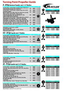


![FT31xD Android Programmers Guide - FTDI Chip [PDF]](https://m.moam.info/img/260x300/ft31xd-android-programmers-guide-ftdi-chip-pdf_6479c351098a9e525c8b4639.jpg)


![[PDF] TCP/IP Sockets in C#: Practical Guide for Programmers](https://m.moam.info/img/260x300/pdf-tcp-ip-sockets-in-c-practical-guide-for-progra_64778022097c474e708bc58b.jpg)
![Cython: A Guide for Python Programmers [PDF] Free ... - Google Sites](https://m.moam.info/img/260x300/cython-a-guide-for-python-programmers-pdf-free-goo_6478244c097c4796708c7add.jpg)


![[PDF] Grokking Algorithms: An illustrated guide for programmers and ...](https://m.moam.info/img/260x300/pdf-grokking-algorithms-an-illustrated-guide-for-p_64775f6c097c474b228c005c.jpg)