Co-Scheduling Hardware and Software Pipelines * R. Govindarajan Supercomputer Education & Research Centre Indian Institute of Science Bangalore, 560 012, India
[email protected]
Erik R. Altman IBM T.J.Watson Research Center Yorktown Heights, NY 10598, U.S.A.
Guang R. Gao School of Computer Science McGill University Montreal, Quebec H3A 2A7, Canada
[email protected]
[email protected]
Abstract
and pipelined supercomputers. Classical hardware pipeline design theory developed more than 2 decades ago was driven by this need [a, 61. In the past decade, technology advances have made it feasible to design very aggressive arithmetic and instruction pipelines in commodity microprocessor architectures, e.g. superpipelined architectures and superscalar architectures. In the meantime, a compiling technique known as software pipelining has become increasingly popular for aggressive loop scheduling for these architectures. A software pipelined schedule overlaps operations from different loop iterations in an attempt to fully exploit instruction level parallelism. A variety of software pipelining algorithms [lo, 7, 3, 5, 12, 21 have been proposed which operate under resource constraints. An excellent survey of these algorithms can be found in 191. In this paper, we propose a design methodology which integrates the scheduling of hardware and software pipelines in a unified framework - termed CoScheduling. The basic observations that lead to the Go-Scheduling framework are: Observation 1: Classical hardware pipeline scheduling theory cannot be directly applied in the presence of software pipelining. The critical missing link is that hardware and software pipeline cycles may have different periods. (Motivating examples for this are provided in Section 2.) Observation 2: Luckily, hardware pipeline scheduling theory may be extended to consider the constraints of software pipelined schedules. These extensions provide key insights and heuristics for improving software pipelining. In particular, by analyzing the reservation table of a hardware (arithmetic) pipeline, we can derive Ugood”initiation sequences that better utilize the pipeline. Use of such initiation sequences narrows the search space of software pipelined schedules, which in turn, reduces the time to construct a schedule. Further, use of “good” initiation sequences may improve
In t h i s paper w e propose CO-Scheduling, a f r a m e w o r k f o r simultaneous design of hardware pipelines struct u r e s and software-pipelined schedules. T w o i m p o r t a n t components of t h e Co-Scheduling f r a m e w o r k are: (1) An extension t o t h e analysis of hardware pipeline design t h a t m e e t s t h e needs of periodic (or software pipelined) schedules. R e s e r v a t i o n tables, forbidden latencies, collision vectors, and state diagrams f r o m classical pipeline theory are revisited and extended t o solve t h e n e w problems. (2) An efficient m e t h o d , based o n t h e above extension of pipeline analysis, t o p e r f o r m ( a ) software pipeline scheduling and (b) hardware pipeline reconfiguration w h i c h are m u t u a l l y “compatible ”. T h e proposed method has been i m p l e m e n t e d and prel i m i n a r y experimental results f o r 1008 kernel loops are reported. Co-scheduling successfully obtains a schedule f o r 95% of t h e s e loops. T h e m e d i a n t i m e t o obtain t h e s e schedules i s 0.25 seconds o n a Sparc-20. Keywords: classical Pipeline Theory, Go-Scheduling, Pipeline Architecture, Software Pipelining, VLIW Architectures.
1
Introduction
Pipelining is one of the most efficient means of improving performance in high-end processor architectures. In order to achieve higher throughput and greater instruction-level parallelism, modern microprocessors contain deeply pipelined function units with arbitrary structural hazards. Historically, design techniques for hardware pipelines with structural hazards have been successfully developed and used in vector *Thiswork was supported by research grants from NSERC, Micronet - Network Centers of Excellence, Canada, and the President’s Grant, Memorial University of Newfoundland, St. John’s, NF, Canada.
52 0-8186-7237-4196$5.00 0 1996 IEEE
the initiation interval (11) in resource-limited loops. We give a number of motivating examples in Section 2. Based on these observations, the Co-Scheduling framework contains two components: (1) We advance the classical pipeline design analysis by first extending reservation tables to cyclic reservat i o n tables (CRT). This allows information on the software pipeline initiation interval I1 to be embedded in the hardware pipeline structures. Important concepts such as for bidd e n latencies, collision vectors, and state diagrams from classical pipeline analysis are revisited and extended for CRTs. This theory facilitates identication of good initiation sequences that maximize the utilization of pipeline stages. (2) On the software (compiler) side, we use a Modulo Initiation Table (MIT) which represents only the initiation pattern of a software pipelined schedule: the resource usage and the structural constraints imposed by the reservation table are captured succinctly by the CRT. Based on the MIT, we present an efficient method for both constructing the software pipeline schedule S and “adjusting” the configuration of hardware pipeline delays to “match” the initiation interval (11). This makes the task of scheduling for architectures involving deep pipelines easier. To demonstrate the feasibility of the co-scheduling approach and its usefulness in software pipelining, we have implemented the proposed method. The major observations are:
complex instruction scheduling to exploit the available instruction-level parallelism. The CO-Scheduling framework proposed in this paper is especially useful for scheduling the new generation deeply pipelined function units. In the following section we motivate the need for the CO-Scheduling framework with a number of examples. In Section 3, the classical pipeline theory is revisited in the context of software pipelining. We present the CO-Scheduling framework in Section 4. Implementation of Co-Scheduling and some preliminary results are discussed in Section 5 . Section 6 compares our approach to other related work. Concluding remarks are presented in Section 7.
2
Background and Motivation
In this section we motivate the need for coscheduling. We make two assumptions in this paper: first, only single-function or static pipelines [6] are considered; second, as in [8],it is assumed that the stages of a pipeline are independent.
2.1
Background
In software pipelining, we focus on periodic linear schedules under which an instruction i in iteration j is initiated at time j * I1 ti, where I1 is the initiation interval or period of the schedule and ti is a constant. Like most software pipelining methods, we assume fized mappi ng where an instruction i (from all iterations) will always be executed on the same function unit (FU) during the course of the loop execution. The minimum initiation interval (MII) is constrained by both loop-carried dependences (or recurrences) and available resources [lo, 7, 5, 9, 21. Loopcarried dependences put a lower bound, RecMII, on MI1 [lo, 71. Another lower bound ResMII on MI1 is enforced by resource constraints. Suppose an instruction uses a pipeline stage s of a function unit (FU) type r (e.g. ADDER), for cl,., cycles. If there are N,. instructions that execute on FU type r and there are F, FUs, then clearly any schedule will have I1 greater than [ N, *d,.,,/F,]. Thus ResMII is the maximumof this bound taken over all stages and FU types:
+
By making use of the good initiation sequences discovered by CO-Scheduling, a schedule was found for 95% of the loops within a small execution time. The median of the execution time was 0.25 seconds. These results are encouraging considering the fact that our experiments used long reservation tables (corresponding to deep pipelines) with arbitrary structural hazards. The CO-Scheduling approach allowed greater pipeline utilization and increased number of initiations per unit time, thus, possibly reducing 11. Our delay insertion approach was a success, allowing a smaller I1 than would otherwise be possible. The CO-Scheduling framework holds great promise for future microprocessor design where aggressive pipelining will be used to accomplish very high processor throughput. Microprocessor vendors are already in the process of designing deeply pipelined ALUs with more than 10 stages. As these high-speed pipelined stages are reused for various functions, arbitrary structural hazards are introduced. This, in turn, requires
And,
MI1 = max (RecMII,ResMII).
(2) Clearly, any initiation interval I1 for which a resource-constrained schedule exists is greater than or equal to MII. i.e. I1 2. MIL
53
Consider the reservation table shown in Figure l(a). The execution time of an instruction in this FU is 6 cycles. Suppose we are interested in constructing a schedule with I1 = 9. To do this we extend the reservation table as shown in Figure 2(a). Notice from Figure 2(a) that initiation of instructions a t time 0 and 1 is permissible [ 6 ] . The resource usage of these two initiations are represented, respectively, by 0 and 1 in the table. As the Table indicates, once two operations are started in the pipeline (at time 0 and l), no further operations can be started until the next iteration begins at time 9. Notice that starting an operation at time step 6 will require the use of Stage 1 at time IU (i.e. 6 cycles after the third x in the Table 2(a)). However, this will interfere with an operation (1*) from the second iteration, and hence is impermissible. More generally, this requirement - that no resource be used by a single iteration at times that are congruent modulo I1 - is known as the modulo scheduling constraint [lo, 91.) Analysis of the reservation table reveals that initiations at time steps U, 3, 6 are permissible and better utilize the pipeline-handling 3 operations every 9 cycles as depicted in Figure 2(b). Compared to the ( 0 , l ) initiation which gives a throughput of 2/9, the (0,3,6) initiation improves the throughput by 3/9 = 1/3. The General Scheduling Algorithm (GSA) outlined above uses any permissible latency sequence, not necessarily an optimal one, in terms of the throughput of the pipeline. If the FU in this example is a critical resource and if a non-optimal greedy initiation, like (0, l),was chosen, then the GSA may have to make a large number of retries or may even fail to produce a valid schedule even though one exists at the given 11. Thus knowing and using the optimal latency sequences in the software pipelining method facilitate producing better schedules and producing them faster (i.e. in less compile time). The GSA models individual stages in an FU as separate resources in the Modulo R e s e r v a t i o n Tables (MRT).As a consequence, for a modern VLIW with less than 10 FUs, the number of columns in the MRT can be very high, increasing the complexity of scheduling. On the other hand, our use of pipeline theory avoids initiations that result in a resource conflict, facilitating the pipelined function unit to be modeled as a single resource. Lastly, the ResMII obtained from Equation 1 is only a loose bound. For example, in the reservation table of Figure l(b), the maximum usage of any stage is only 2. Thus the ResMII for this FU, as computed However, since lausing Equation 1, will be tencies 0 to 3 are forbidden, two initiations need to
Figure 1: Example Reservation Tables Next we briefly review existing software pipelining methods that are capable of handling structural hazards [2, 7, 51. In general, these methods construct a Modulo Reservation Table (MRT) to keep track of the resources used by already scheduled instructions. The MRT contains I1 rows and one column for each resource. If an FU contains structural hazards, each pipeline stage must be considered as a different resource in the MRT. Given the MRT, the existing scheduling algorithms, henceforth referred to as General Scheduling Algorithms (GSA), proceed by scheduling operations based purely on the availability of resources. Which operations get scheduled first is decided by a priority function which differs across various software pipelining algorithms. If an operation cannot be scheduled, the algorithm selectively unschedules a number of operations and re-schedules them again. In hardware pipelines, the resource usage of various pipeline stages are represented by a two dimensional Reservation Table [ 6 ] . If two operations entering a pipeline f cycles apart would subsequently require one (or more) of the pipeline stages at the same time, f is termed a forbidden latency. Operations separated by permissible latencies have no such conflicts. A collision vector has length equal to the pipeline latency and contains a 1a t all forbidden latencies, and a 0 a t all permissible latencies. A state diagram represents the listing of all initiation sequences that are permissible. Refer to [6] for the construction of state diagrams. Analysis of the state diagram reveals what initiation sequence(s) or latency sequences maximize the utilization and throughput of the pipeline. Further details can be found in [ 6 ] . 2.2
Need for Analysis of Pipeline Structure
To the best of our knowledge, none of the existing software pipelining approaches [2, 7, 51 make any explicit use of the analysis developed in classical pipeline theory. With the help of a few examples, we demonstrate that rectifying this omission can greatly improve the schedule produced.
[VI.
54
(a) 0,1Initiation. (* ops from 2nd Iteration)
Figure 2: Extended Reservation Tables from Figure l(a) with Multiple Iterations
4
(b) State Diagram
(a) Reservation Table
Figure 3: An Example Reservation Table and its State Diagram
2, 4, and 9 (or 9 mod 8 = 1). It can be seen that collisions occur at time steps 2, 5 and 4 in stages 1, 2 and 3 respectively. More specifically, a collision occurs between two initiations at time 2 and 4, even though the latency between these two initiations ( f = 2) is permissible according to the hardware pipeline theory. This is not unexpected since the state diagram is obtained for a reservation table with 7 columns and was derived without a “wrap-round” resource usage in mind. Further the classical pipeline theory [8, 61 does indicate that 2 is an impermissible latency for any cycle with period 8, since 2 is the complement of the forbidden latency 6 in the modulo space with I1 = 8. However, the focus in these works [8, 61 is on how to reconfigure the hardware pipelines for a given latency cycle. Whereas here we are interested in finding an optimal latency cycle for the given 11.
be separated by at least 4 cycles, as indicated by the state diagram of the FU. Hence the actual ResMII for this FU is [?I, roughly twice as large as the bound given by Equation 1.
2.3
The need for Co-Scheduling
By analyzing the reservation table of the FU using classical pipeline theory, one can obtain latency cycles that maximize the throughput and utilization of the pipeline. But the period’ of the latency cycle may or may not match the initiation interval of the software pipeline.2 As a consequence some of the legal latency cycles predicted by the classical pipeline theory may violate the modulo scheduling constraint for the given 11. We illustrate this with the help of another example. Consider the reservation table and its state diagram shown in Figures 3. Assume I1 = 8. In the state diagram the latency cycle (2,2,5) has the Minimum Average Latency, M A L = = 3 . In Figure 4 we show the result of initiating instructions at time step
The self cycle in state iiiiOOi0, with a MAL of
4, is the permissible cycle for I1 = 8 with the maximum utilization. As this example shows, the state diagram constructed using the classical pipeline theory does not account for the software pipelining 11. As a consequence the modulo scheduling constraint may be violated by some latency cycles identified as legal by the state diagram. In the following section we show how to extend the classical pipeline theory to achieve the simultaneous scheduling of hardware and software
‘The s u m of the latency values in the latency cycle is the period of the latency cycle. 21t is important to distinguish between the period of the hardware pipeline and the initiation interval of the software pipelined schedule. Henceforth the terms “period”and “initiation interval” are respectively used to refer to the periods of hardware and software pipelines.
55
if this is not the case, it is possible to satisfy the modulo scheduling constraint by modifying the hardware so as to delay all but one of the operations mapping to the same time t.3 Since there are at most dmaz(r) x marks in any row, and dmaz(r) 5 11, it is always possible to delay an X mark to a column such that the resulting CRT has at most one X mark in each column. This forms the basis of Lemma 3.1. Figure 4: Initiation of Instructions at (2, Modulo Reservation Table
4, 9)
Lemma 3.1 It is always possible t o satisfy t h e m o d u lo scheduling constraint by introducing appropriate delays in t h e reservation table.
in the
A formal proof of this as well as other lemmas is presented in [4]. Figure 5(a) shows the CRT of the reservation table shown in Figure l(a), when I1 = 9. Next we define several terms.
pipelines.
3
Modulo-Scheduled Pipelines
In this section we revisit classical pipeline theory in the context of software pipelining. To differentiate our approach from the classical pipeline theory, we refer to our pipelines as Modulo-Scheduled (MS) pipelines. In Section 3.2, we develop the theory behind MS-pipelines which forms the basis for our coscheduling framework.
3.1
Definition 3.1 (Cyclic Forbidden Latency) A latency f 5 11 i s said be a cyclic forbidden latency i f there exists at least one row in t h e CRT where t w o entries (X m a r k s ) are separated by f c o lu m n s (considering t h e wrap-around of columns). M o r e precisely, there exists a stage s s u c h t hat col um n s t and (t + f) mod I1 both cont ai n a n X m a r k .
Preliminaries
It can be easily seen that in an MS-pipeline, a latency value f greater than I1 is equivalent to f mod 11. The set of all cyclic forbidden latencies is referred to as the cyclic forbidden latency set.
The reservation table of a hardware pipeline is represented by an m, x 1, reservation table where m, is the number of stages in the pipeline and I,. is the execution time (latency) of an operation executing on FU r . We use the symbol d,,, to denote the number of cycles stage s in the pipeline is used. Define L G z ( r ) as the maximum of d,,# over all stages in the pipeline. In MS-pipelines, each instruction must be initiated in the pipeline every I1 cycles. Therefore it is appropriate to use a reservation table with I1 (rather than Z,.) columns. Notice that the relationship between ,Z and I1 could be (1) I1 > I, , (2) I, > 11, or (3) I, = 11. If I1 > l,, the reservation table may be extended to I1 columns (with the additional columns all empty). If I1 < I,, the reservation table may be folded. Thus for stage s an X mark at time step t in the original reservation table appears at time step t mod I1 in the folded reservation table. If I1 = I,, nothing need be changed. We call the resulting reservation table the cyclic reservation table (CRT). With the folding required in case (2), multiple X marks separated by I1 may be placed in the same column of the CRT. Fortunately, the modulo scheduling constraint already prohibits such occurrences. Thus if the reservation table satisfies the modulo scheduling constraint, the cyclic reservation table will not have two X marks in the same column of the CRT. However,
Definition 3.2 (Cyclic Permissible Latency) A latency f 5 I1 i s said t o be a cyclic permissible latency i f f i s n o t in t h e cyclic f orbi dden l ate n cy set. The cyclic forbidden latency set for the CRT in Figure 5(a) is (0,2,4,5,7}. The cyclic permissible latencies are 1, 3, 6, and 8.
3.2
State Diagram for MS-Pipelines
Our interest in co-scheduling is to obtain latency sequences that maximize the number of initiations in I1 cycles. In order to derive this, we construct the state diagram for a CRT - henceforth referred to as the Modulo-Scheduled State Diagram (MSstate diagram) - in much the way as is done in classical pipeline theory. The initial state in the MSstate diagram represents an initiation at time step 0. We want to find how many more initiations are possible in this pipeline, and at what latencies. We define a cyclic collision vector to represent the state after a particular initiation. 'As this must be done on a loop by loop basis, we hope that hardware designers will consider making such a capability available in the instruction set of future processors.
56
I
I
101011010 1,8\
8
(b) State Diagram for the CRT Figure 5: A Cyclic Reservation Table and its State Diagram
+
+
will be initiated at time step 0 I1 = 0 9. This operation will have a latency 2 with the operation initiated at time step 11. Since 2 is in the cyclic forbidden latency set, there will be a collision. The MS-state diagram for the CRT in Figure 5(a) is shown in Figure 5(b). Multiple arcs from state Si to Sj are represented by means of a single arc with multiple latency values, e.g. in Figure 5(b), the state iiiillili can be reached from the initial state with a latency value of either 1 or 8. An inspection of the modulo scheduled state diagram (refer to Figure 5(b) reveals that there are no directed cycles in the MSstate diagram. This is formally established in [4].
Definition 3.3 (Cyclic Collision Vector) A Cyclic Collision vector is a binary vector of length 11, with t h e bits numbered f r o m 0 t o I1 - 1. Iff i s forbidden in t h e current state t h e n t h e f -th bit in t h e cyclic collision vector is 1. Otherwise it is 0. For the CRT in Figure 5(a), the initial cyclic collision vector is 101011010. The construction of the MS-state diagram proceeds as follows.
Procedure 1 Construction of State Diagram: Step 1 Start with the initial cyclic collision vector. Step 2 For each permissible latency p in the current state, i.e. all bits p in the collision vector whose value is 0, derive a subsequent state as follows.
Theorem 3.1 T h e collision vector of every state S in t h e M S - s t a t e diagram derived according t o Procedure 1 represents all permissible (and forbidden) latencies in that state, taking i n t o account all initiations m a d e so f a r t o reach t h e state S.
(a) R o t a t e - l e f t the collision vector by p bits. (b) Logically OR the resulting vector with the initial cyclic collision vector. The resulting collision vector is a subsequent state. (c) Place an arc with value p from the previous state to the new state.
A proof of this theorem is presented in [4]. A path in the MS-state diagram is a set of latency
Observe that there is a very close resemblance of Procedure 1 to the state diagram construction in the classical pipeline theory. The main difference is that in Step 2(a) of Procedure 1 a r o t a t e - l e f t operation is performed rather than a shift-lef t operation. For example, the cyclic collision vector ioiollolo when rotated left by 3-bits gives 0110iOiOi. Notice that the rightmost 3-bits in rotate left is 010 indicating that a latency 8 is forbidden (apart from latencies 0, 2, 4, and 5) in the new state. More precisely, after two initiations at time steps 0 and ( 0 + 3 ) , a latency of 8 at time step 0 + 3 + 8 = 11 will cause a collision. Why? Because, another instance (from the following iteration) of the instruction which was initiated at time step 0
values, one associated with each arc along a path, from the initial state to the current state. For example, there is a path with latency values {3,3} from 10~011010to 1iiilllll in Figure 5(b). Since the initial state itself represents as initiation at time step 0, the latency values {3,3} correspond to initiations at time steps (0, (0 3), (0 3 3)) = {0,3,6}. The length of a path is the number of states encountered on the path. Further, the longest path corresponds to the maximum number of initiations possible in a pipeline within a software pipeline cycle. For the MS-state diagram shown in Figure 5(b), the maximum number of initiations is 3 and the corresponding initiations are at {0,3,6h
+
57
+ +
4
CO-Scheduling the Hardware and Software Pipelines
7
Resewation Tables
dGI AiM"
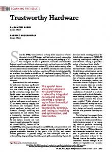
In this section we detail how our CO-scheduling approach generates schedules for FUs with structural hazards. The next section provides an overview of CoScheduling, while Sections 4.2 and 4.3 detail the two major components of Co-Scheduling.
ModifiedPipeline Theory
(Procedure 2)
Sequence
4.1
Overview of Co-Scheduling
SCS: Slackness Based Co-Scheduling
Figure 6 outlines our approach. We begin by calculating MI1 from Equation 2. As the example in Section 2.2 showed, the MI1 from Equation 2 is sometimes too low. In the next Section, we detail how to handle this situation. Once an appropriate I1 is found, using the framework just outlined in Section 3, we attempt to find (one of) the longest latency sequence(s), i.e. we try find at what times operations can be introduced into the pipeline so as to keep it maximally utilized. Next , to perform software pipelining, we introduce SCS, a slackness based co-scheduling algorithm based on Huff's Slack Scheduling [5]. The key distinction between SCS and Huff's approach is that instead of placing operations at any permissible time, S CS places them only at times given by the latency sequence. If S C S fails to find a schedule or fails to find one within a reasonable period of time, I1 is incremented, and the whole process is tried again. Once a schedule is found, the corresponding pipeline delays must be noted. That is, the prologue code to the loop must contain instructions telling the hardware pipelines to place delays (buffers) at the necessary locations.
4.2
I
ProlDgue lnsrmctionsto Insert Delavs in Pioeline
1
Figure 6: Outline of Slack Co-Scheduling Algorithm. constraint. This may introduce delays* in the CRT which, in turn, can increase the execution time of instructions. As a consequence RecMII may be affected. Starting from the MI1 value obtained from Equation 2 (in Section 2.1), we use the following iterative procedure to determine the smallest 11.
Procedure 2 Find-Minimum11 (11) where Step 1 I1 = max(MII,max,.[d,,,(r)]}, L a Z ( r )is the maximum number of X marks in any row of RT, .
Step 2 Repeat Steps 2.1 to 2.6 until a valid I1 satisfying resource, recurrence and modulo scheduling constraints is found
Determining t h e Minimum I1
Step 2.1 For each FU type r do Step 2.1.1 Construct CRT, from RT,. Introduce delays to satisfy modulo scheduling constraint if required. Step 2.1.2 If the introduction of delays has increased the execution time, then 1, is set appropriately.
We use the following notation throughout this section. Our aim is to construct a software pipelined schedule for a loop L to run on an architecture with h different types of FUs (e.g. Adder, Multiplier, etc.). The usage of resources (pipeline stages) in FU type T is specified by a single reservation table RT,, The execution time of an instruction that executes on FU type T is same as the length of the reservation table I,. Further, each FU type T has F, pipelines. The loop L has N, instructions that are executed on the F, pipelines of FU type r . As mentioned in Section 2.1, the minimumI1, MII, is max(ResMI1, RecMII). The ResMII bound is loose. Further for an initiation interval 11, the CRT has length I1 and must satisfy the modulo scheduling
Step 2.2 RecMII is calculated with the new values of 1,. Step 2.3 If the new RecMII > 11, increment I1 by 1 and go back to Step 2.1. 4T~o alternatives to satisfy the modulo scheduling constraints are to unroll the loop and to increase the I1 by 1. However, in this paper, we follow the approach used in the classical pipeline theory, namely introducing delays in the pipeline.
58
The difference lies in how a time is chosen within the slack range. The original Slack Scheduling permitted nodes to be placed anywhere in their slack range. SCS, on the other hand, allows nodes to be placed only at points given in the latency sequence, even if this means avoiding some times that would yield a legal partial schedule. In this way, SCS takes a more global view of when instructions should be scheduled and avoids getting trapped at greedy local maxima, the way the original can.5 To clarify matters, we illustrate SCS through an example. Assume: (a) I1 = 5, (b) one type of function unit, (c) one copy of it, (a) latency Sequence from Procedure 2: 0, 3, (e) one operation already placed at time 1 (mod 11),and (f)new operation must be placed at time 3 or 4 to obey data dependence constraints. Since the first operation has already been placed at time 1, the new operation can be placed only at times matching the latency sequence. Since time i+O=i has already been used, the only other legal value is 1+3=4. Thus time 4 is chosen, even though time 3 may also have produced a legal partial schedule. We chose to use Slack Co-Scheduling because of the good performance achieved by the original Slack Scheduling [5]. However, modified versions of other modulo scheduling techniques [7, 3, 12, 111 using a fixed I1 could have been used instead. The main novelty of our approach lies in Procedure 2. The fact that it can work with variants of many other approaches indicates its versatility. Recall that SCS, at least the current implementation, works with only one latency sequence. This may affect: (a) The existence of a resource-constrained schedule for a given 11. This is true, even if the choice is made only among latency sequences that result in maximum initiations. (b) The quality of the schedule in terms of the number of registers used by the schedule. It is possible, in principle, to extend our SCS algorithm to use multiple latency sequences. We plan to investigate this in future.
Step 2.4 Else, derive the MS-state diagram for the CRTs, CRTl to CRTh. Let M a z , represent the maximumnumber of initiations possible in FU type r and L, be a corresponding latency sequence that achieves the maximum initiations. Step 2.5 If, for each FU type r , F, 2 go to Step 3; Step 2.6 Else, increment I1 by 1 and go back to Step 2.1. Step 3 End. It can be observed that when Procedure 2 terminates, the I1 value satisfies, dependency, resource and modulo scheduling constraints. Further, it can be established that the I1 obtained from Procedure 2 is the minimum I1 [4].
4.3
SCS Algorithm
In our CO-scheduling framework, resource usage of different pipeline stages, and the initiation of operations in pipeline are maintained using the CRT and a ModuZo Initiation Table (MIT). More precisely, the CRT is used to keep track of the resource (pipeline stage) usage and avoid resource conflicts. Notice that our CRT, constructed as discussed in the previous section, does satisfy the modulo scheduling constraint, even in the presence of structural hazards. The modulo initiation table indicates only when operations are introduced in the pipeline. Compared to the MIT, the Modulo Reservation Table (MRT), used in other software pipelining methods [7, 5, 9, 111, represents both the initiation time of instructions and their resource usage. Due to this dual role, MRT consists of a larger number of columns, one for each stage of the pipelines in the architecture. This increases the complexity of software pipelining. In contrast, the MIT only stores when operations are initiated in the pipe. Hence, it consists of fewer columns, equal to the number of pipelines in the architecture. After computing an I1 and a corresponding optimal latency sequence - optimal in terms of the throughput of a hardware pipeline structure - as detailed in Procedure 2, SCS, our slackness based co-scheduling algorithm is used to find a schedule fitting I1 and the Zatency sequence. The basic notion of Huff’s original Slack Scheduling [5] was to schedule nodes in increasing order of their slackness: the difference between the earliest time at which a node may be scheduled and the latest. Slack is a dynamic measure and is updated after each node is scheduled. These points remain in
5
Experimental Results
To evaluate CO-scheduling we implemented it and tested it on 1008 loops taken from a variety of benchmarks: specfp92, specint92, livermore, linpack, and the NAS kernels. All of these loops contain fewer than 64 operations, with a median of 7 and a mean of 12. For the experiments, we considered an architec~-
Ehfairness, we note that the original was applied only to function units with clean pipelines and function units (divide) with no pipelining.
scs.
59
~i
ture with 2 Integer Units, one each of the remaining units: Load, Store, FP Add/Subtract, FP Multiply and FP Divide. To exercise our co-scheduling method fully, we chose long reservation tables (representing deeper pipelines) with arbitrary structural hazards. In particular the FP add and multiply units have a depth of 5 and 7 pipeline stages respectively, while the divide unit has a depth of 22 stages. The reservation tables are chosen in such a way that their execution latency of operations match with those of some state-of-the-art microprocessor architecture. Further they re-emphasize the point that the Co-Scheduling framework is especially for deeper pipelines of future architectures. For pragmatic reasons, we restricted our implementation to take a maximum of 3 minutes to construct the schedule for each loop. We also limited the size of the MS-state diagram generated to 2000 collision vectors. While the latter restriction had no effect on the constructed schedule, the former allowed only 95% (or 958) of the test loops to be scheduled under the given resource constraints. The schedule for the remaining 5% of the loops could be obtained either with a longer compilation time or starting with a higher MII. Table 1 details how well the I1 compares to the lower bound MII. As can be seen, in 41% of loops, we achieve I1 = MIL Further, for 72% of the test loops, the I1 achieved was within 4 cycles from the lower bound, MII. This turns out to be within 1.25 * MII. Our CO-Scheduling method, and all software pipelining methods in general, tend to take longer to construct a schedule when the function units are deeply pipelined and involve arbitrary structural hazard. To the best of our knowledge, this is one of the first extensive experimental results for architectures involving deeper pipelines with arbitrary hazards6. In the future, we plan to compare our co-scheduling method with other software pipelining methods [5, 111. Additional statistics characterizing the loops and resulting schedules are given in Table 2. The median time to schedule a loop was 0.25 seconds and the (geometric) mean was 0.50 seconds on a Sparc 20. The median I1 was 12 and the geometric mean I1 was 14.3. 89.9% of the loops required no more than 32 registers. Thus in a large number of cases, the schedule produced by CO-scheduling does not require any further (register) spill code. From our experiments, we observed that the intro-
I1 - MI1
3 4
# of Cases %-age
50 113
5.0 11.3
No Schedule in 3 minutes Table 1: Difference between I1 achieved and MII.
Table 2: Comparison of I1 achieved to MII. duction of delays in Procedure 2) does not increase 11. This is partly due to our assumption of no interstage dependences. However, the insertion of delays does improve I1 for a small number, 17, of the test loops. The percentage improvement in I1 of our schedules against a scheduling method which does not insert delays (to satisfy modulo scheduling constraint) is roughly 3%. Further, our experiments revealed that the bound (from Equation 2) is quite tight, which is a surprise. Similar results were observed for architectures involving either shallow or deep pipelines. Hence one may conclude that these observations are somewhat independent of the structure of the pipelines. Further investigation of these effects may be required to derive strong conclusions.
6
Related Work
Resource-constrained software pipelining has been studied extensively by several researchers and a number of modulo scheduling algoTithms [2, 3, 5, 7, 10, 11, 121 have been proposed in the literature. A comprehensive survey of these works is provided by Rau and Fisher in [9]. As mentioned in Section 4.3, the CoScheduling method discussed in this paper uses a variation of Huff’s Slack Scheduling method [5].
Similar experiments were conducted for shallow pipelines involving fewer structural haeards. In those experiments the performance of the co-scheduling framework is even better, requiring a (arithmetic)mean execution time of only 1.25 seconds and obtaining schedules for all but 2% of test loops in less than 1 minute. These results are reported in [4].
60
The work presented in this paper is unique in the sense that it coordinates the scheduling of both hardware structures and software pipelined schedules in a single Co-Scheduling framework to achieve high instruction level parallelism. To the best of our knowledge, there is no explicit use of the well-developed classical pipeline theory (or its adaptation) in software pipelining methods. In contrast our Co-Scheduling approach does so. The CO-Scheduling framework complements other related work in resource-constrained software pipelining by considering a special class, viz. a d h m e t i c pipelines. It is very effective for handling deep arithmetic pipelines. There is another major difference between our CoScheduling and other approaches. In Co-Scheduling, the software pipeline initiations are represented in a Modulo Initiation Table while resource conflicts of hardware pipeline structures are handled in the Cyclic Reservation Table. In contrast other modulo scheduling algorithms use a single Modulo Reservation Table t o represent both resource conflicts and initiation time. Separating them, as in our method, facilitates achieving better and faster schedules. An attractive feature of the CO-Scheduling framework is that it opens up new avenues by facilitating the use of classical delay insertion technique to improve instruction level parallelism. Modulo-Scheduled pipelines discussed in this paper are different from pipelines scheduled a t (fixed) latency cycles [8, 6, 11. The period of the latter depends only on the resource usage of the pipeline, while in the former, it is governed both the resource usage and the recurrences in the loop considered for scheduling.
7
References [I] J.K. Chaar and E.S.Davidson. Cyclic job shop scheduling using collision vectors. CSE-TR-169-93, Univ. of Michigan, Ann Arbor, MI., Aug. 1993 [2] J. C. Dehnert and R.A. Towle. Compiling for Cydra 5. J . of Supercomputing, 7:181-227, May 1993. [3] F. Gasperoni and U. Schwiegelshohn. Efficient algorithms for cyclic scheduling. Res. Rep. RC 17068, IBM T. J. Watson Res. Center, Yorktown Heights, NY, 1991. [4] R. Govindarajan,
E. R. Altman, and G. R. Gao. Co-scheduling hardware and software pipelines. ACAPS Tech. Memo 92, Sch. of Comp. Sci., McGill U., MontrCal, QuC., Jan. 1995. In ftp://ftpacaps.cs.mcgill.ca/pub/doc/memos.
[5] R. A. Huff. Lifetime-sensitive modulo scheduling. In Proc. of the ACM SIGPLAN '93 Conf. on Programming Language Design and Implementation, pages 258-267, Albuquerque, NM, Jun. 23-25, 1993. [6] P. M. Kogge. The Architecture of Pipelined Computers. McGraw-Hill Book Company, New York, NY, 1981. [7] M. Lam. Software pipelining: An effective scheduling technique for VLIW machines. In PTOC.of the SIGPLAN '88 Conf. on Programming Language Design and Implementation, pages 318-328, Atlanta, GA, Jun. 22-24, 1988. [8] J.H. Pate1 and E.S. Davidson. Improving the throughput of a pipeline by insertion of delays. In Proc. of the 3rd Ann. Symp. on Computer Architecture, pages 159-164, Clearwater, FL, Jan. 19-21, 1976.
Conclusions
[9] B. R.Rau and J. A. Fisher. Instruction-level parallel processing: History, overview and perspective. J . of Supercomputing, 7:9-50, May 1993.
In this paper we have proposed Co-Scheduling, a unified framework that performs the scheduling
[lo] B. R. Rau and C. D. Glaeser. Some scheduling techniques and an easily schedulable horizontal architecture for high performance scientific computing. In Proc. of the 14th Ann. Microprogramming Work., pages 183-198, Chatham, MA, Oct. 12-15, 1981.
of hardware and software pipelines. The proposed method uses and extends classical pipeline theory to obtain better software pipelined schedules, as has been demonstrated through both examples and experimental results. As part of CO-Scheduling, we have introduced the Modulo Initiation Table (MIT) and Cyclic Reservation Table (CRT) as alternatives to the standard modulo reservation table. We have implemented CO-scheduling and run experiments on a set of 1008 loops taken from various benchmark suites. We have experimented our CO-Scheduling method specifically for architectures involving deeper pipelines and arbitrary structural hazards. The median time for Go-Scheduling to handle one loop was 0.25 seconds.
[ll] B. R. Rau. Iterative modulo scheduling: An algorithm for software pipelining loops. In Proc. of the 27th Ann. Intl. Symp. on Microarchitecture, pages 63-74, San Jose, CA, Nov. 30-Dec.2, 1994. [12] J . Wang and E. Eisenbeis. A new approach to software pipelining of complicated loops with branches. Res. rep. no., Institut Nat. de Recherche en Informatique et en Automatique (INRIA), Rocquencourt, France, Jan. 1993.
61