COMBINED SPATIAL AND SUBBAND BLOCK CODING ... - CiteSeerX
Recommend Documents
still image transmission system based on subband coding and 64-QAM. ... a lot of work in the area of combined source and channel coding during the re- ... the mechanisms for noise generation in communication sys- tems. Section ... For noisy channels,
Mar 1, 2017 - 4.7.1 Multiresolution Analysis and Two-Scale Equation . ..... The first wavelet (the only example for a long time!) was found by Haar .... signal x from some space S, where S can be finite-dimensional (for ...... matrix C with a first l
Mar 1, 2014 - 2.4.1 Signal Expansions and Nomenclature . ...... for example the wavelet packet expansion introduced by Coifman and ...... The answer is.
Apr 4, 2016 - mirror filters (QMF) in the late 1970's, and by Crochiere, Webber and ...... (d. ) D iscrete-tim e. F ou rier tran sform of fi n ite- len gth seq u en ce. F.
Apr 2, 2014 - has n(n â 1)/2 degrees of freedom (up to a permutation of its rows or columns and a sign change in each
in the new JPEG 2000 standard 5] for which work is just getting underway. ..... Let Y1;:::;Yn be i.i.d. observations from a Laplacian source with pdf f (y) = 1. 2 e? y.
Apr 2, 2014 - Speech/audio, image and video compression using transforms, quantization and entropy coding are discussed
PDF online, PDF new Subband Image Coding (The Springer International Series in Engineering and Computer Science), Online
Abstract. The combination of the Radial Basis Function. (RBF) based-equalizer with decision feedback and block turbo decoder is studied. In block turbo.
Tor A. Ramstad. Norwegian University of Science and Technology. Department of Telecommunications. N-7491, Trondheim, Norway [email protected].
MULTIRATE DSP USING DECIMATION AND INTERPOLATION .... Subband coding is effectively implemented by Multirate signal processing. .... T. Dutoit, Glottal Source Estimation Using an Automatic Chirp Decomposition, Lecture Notes in.
This work was supported by Samsung Electronics the block artifacts are ... Also de ne the elements of the DCT base matrix as follows. F= 2. 6664 x1 x2. 0 x3 0. 0.
Stretch Coding and Block Coding: Two New Strategies to Represent. Questionably Aligned DNA Sequences. Daniel L. Geiger. Research Associate, Santa ...
Soo-Chul Han and John W. Woods ... D) subband/wavelet coding scheme for very low bit- rate video ..... 6] S. Choi and J. Woods, \Motion-compensated 3-.
Aug 14, 1998 - Adaptive Source-Channel Subband Video Coding .... bits are allocated to di erent transform or subband coe cients in a rate-distortion ...... tizers," IEEE Transactions on Acoustics, Speech, and Signal Processing, vol. 36, no.
ing/modulation for transmission over noisy chan- nels. In 1], the ... channel-to-noise ratio (CSNR), there is an opti- mal value of ... noisy channels is reduced at the cost of less cod- ... able length coding, it is not possible to take the signi ca
Nov 1, 2002 - Section III generalizes the case of NT = 2 transmit antennas to more than ...... [2] I. Ghauri and D.T.M. Slock, âLinear receivers for the DS-CDMA ...
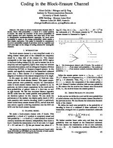
AbstractâWe study an M-ary block-erasure channel with B blocks, where with ... the error probability analysis in previous work by Lapidoth and shed some light ...
Mar 31, 2003 - ENEE624 Advanced Digital Signal Processing. Instructor: Dr. Babis Papadopoulos. 1 Introduction. In this p
When the file size is large it will take much a longer time to build the Huffman ... and puts some overhead of rearranging the code tree every time the sender ...
TECHNICAL REPORT No. TR2000/06/04. 1. Abstract. The wide use of digital media during the past few years, has led to an increase of digital piracy and ...
independent of the above points. In this paper, we propose a PAPR reduction
technique which combines µ-law companding technique and encoding
technique.
same length; they are actually close to the coding gains obtained with a DCT of length 2M. An MLT-based adaptive transform coder (ATC) for speech signals has ...
COMBINED SPATIAL AND SUBBAND BLOCK CODING ... - CiteSeerX
[9] Marc Antonini, Michel Barlaud, Pierre Mathieu, and. Ingrid Daubechies, âImage coding using wavelet trans- form,â IEEE Trans. on Image Processing, vol. 1, no ...
COMBINED SPATIAL AND SUBBAND BLOCK CODING OF IMAGES Frederick W. Wheeler and William A. Pearlman Electrical, Computer and Systems Engineering Dept. Rensselaer Polytechnic Institute Troy, NY 12180, USA [email protected], [email protected] ABSTRACT This paper describes a low-memory cache efficient Hybrid Block Coder (HBC) for images in which an image subband decomposition is partitioned into a combination of spatial blocks and subband blocks, which are independently coded. Spatial blocks contain hierarchical trees spanning subband levels, and are each encoded using the SPIHT algorithm. Subband blocks contain a block of coefficients from within a single subband, and are each encoded by the SPECK algorithm. The decomposition may have the dyadic or a wavelet packet structure. Rate is allocated amongst the sub-bitstreams produced for each block and they are packetized. The partitioning structure supports resolution embedding. The final bitstream may be progressive in fidelity or in resolution. 1. BACKGROUND Set splitting techniques for coding bitplanes of image subband decompositions have received much attention recently. Two fundamental approaches have been taken. EZW [1] and SPIHT [2] use hierarchical spatial tree sets that extend across subbands. These tree-based algorithms are designed to exploit the correlation of coefficient magnitudes that occurs across bands of a decomposition. SPECK [3] and SWEET [4] use rectangular sets within each subband and quad-tree splitting. These algorithms exploit magnitude correlation within, but not between bands. This work develops codecs based on SPIHT and SPECK. Though the types of sets used and the set splitting rules differ, both SPIHT and SPECK follow the same basic procedure. For each bitplane, they first communicate to the receiver which coefficients are newly significant, that is, which coefficients have their MSB in the current bitplane. To do this the subband decomposition is divided into sets of coefficients. Each set is tested to determine whether any coThis work was supported in part by the National Science Foundation under grant numbers NCR-9523767 and EEC-9812706, and by a fellowship from Sun Microsystems.
efficient within is newly significant. This test result is transmitted. If significant, the set is split and the significance test is applied recursively. This process iteratively narrows in on the newly significant coefficients and efficiently encodes clusters of insignificant coefficients. After newly significant coefficients are found in a bitplane, all coefficients found significant for any previous bitplane are refined by having their bit from the current plane transmitted. 2. MOTIVATION This work is motivated by compression, memory usage and memory cache efficiency. In previous reports, SPIHT [2] was generally superior to SPECK [3] considering rate vs. distortion performance. However, SPECK has been found to be most competitive in images with elevated high spatial frequency energy, such as the barbara image. We are attempting to capitalize on this difference with the Hybrid Block Coder (HBC) presented here. HBC applies tree-based SPIHT to low-frequency bands and block based SPECK to high-frequency bands. Discrete wavelet transform based codecs like SPIHT and SPECK generally encode an entire image as one unit. The image is transformed as a whole, and then the algorithm encodes the coefficient values. Unfortunately, there is no structure to the order in which the coefficient values are accessed by the SPIHT and SPECK algorithms. With such an unstructured access requirement, memory cache systems are of no benefit because of frequent cache misses. Effective automatic memory caching relies on temporal and spatial correlation of memory accesses. In order to operate efficiently in a caching environment, we group the wavelet coefficients into small blocks which are entropy coded independently, in turn. With blocks small enough to fit into cache memory, performance is greatly improved. 3. HYBRID SUBBAND PARTITIONING The hybrid partitioning scheme divides the subband transform coefficients into a combination of spatial blocks and
LL3 LH3
LL2
LL1
LH2
LH1
LH1 HL2
HH2
HL3 HH3
HL2
LH2
LH1 HH2
LL0 HL1
HH1
HL1
HH1
HL1
HH1
Fig. 1. An image, and its 1, 2 and 3 level dyadic wavelet transforms are shown. The whole original image is labeled LL0 for the sake of notational continuity. T0 T1 T0 T1 T2 T3 T2 T3 T0 T1 T0 T1 T2 T3 T2 T3
T0 T1 T2 T3
T0 T1 T0 T1 T2 T3 T2 T3
T0
T1
T2
T3
T0
T1
T0
T1
T2
T3
T2
T3
B0
B1
B2
B3
B4
B5
B8
B9
B6
B7
B10
B11
Fig. 2. Shown is an example of hybrid partitioning with L = 4 decomposition levels and K = 1 levels in subband blocks. Bands from LL1 are partitioned into spatial blocks. The highest frequency bands (LH1, HL1, HH1) are partitioned into subband blocks. Solid lines separate subbands, and dotted lines separate spatial and subband blocks. Each section that is a member of a spatial block is labeled with a T followed by the index of the spatial block. The sections that comprise a spatial block are not contiguous. Each subband block is labeled with a B followed by the index of the subband block. There are 4 spatial blocks and 12 subband blocks. Each block has the same number of coefficients. subband blocks. The structure of the dyadic wavelet decomposition is diagrammed in Fig. 1. An L level dyadic wavelet decomposition is partitioned into non-overlapping spatial and subband blocks, as shown in Fig. 2. For some level K , usually 1 or 2, all codevalues from band LLK are partitioned into spatial blocks. Generally K < L, so the LLK band no longer exists as a whole, but has been further subdivided. All bands not in LLK are partitioned into subband blocks, which are rectangular regions within a single subband. Each spatial block holds one or more hierarchical trees, which contain the tree based sets of the SPIHT algorithm, with high frequency bands pruned. Each subband block contains the square sets of the SPECK algorithm. Thus, the core SPIHT algorithm is readily modified to independently encode the spatial blocks and SPECK is likewise modified
to encode the subband blocks. If K = 0, all coefficients are in spatial blocks, resulting in a spatial block SPIHT (SB-SPIHT) codec [5]. If K > L, then all coefficients are in subband blocks, and we have a subband block SPECK (SB-SPECK) codec, which is similar to the SBHP codec [6]. The hybrid block image coder is so named because it is a hybrid of these two schemes. This hybrid partitioning technique can be utilized with non-dyadic decompositions as well. Let P 1 be the decomposition in which the 3 highest frequency bands are each further subdivided into 4 subbands; and P 2 be the decomposition which starts with the P 1 decomposition, but the 15 (level 1 and 2) highest frequency bands are further subdivided into 4 subbands each. Hybrid partitioning and the codec described here can be applied to these decompositions as well. The high frequency bands are partitioned into subband blocks and coded with SPECK. Hybrid partitioning, with K > 0, facilitates resolution scalability. A smaller replica of the encoded image, resulting from the omission of high frequency bands, can be recovered from a truncated bitstream if the packetized bitstream is assembled properly. Strictly spatial tree based compression schemes, such as EZW and SPIHT, in general, do not lend themselves to this property. Because the trees extend to the highest frequency bands, and information bits for the different levels are intermixed in the bitstream, it is more difficult to extract just the information for low frequency bands from the bitstream.
4. ROLLING WAVELET TRANSFORM So that the overall system is cache efficient, and to reduce the memory requirements of this system, we employ a linebased transform engine [7]. At the encoder, the image is read line by line from the top. After each line, all possible computation with the data received thus far is completed. For each decomposition level, a buffer of F lines is required, where F is the vertical filter length. This buffer holds a sliding window of intermediate coefficients awaiting a vertical transform. A memory buffer is created for each block, but not allocated until it is needed. The line-based transform process makes final coefficients ready one row at a time in each band. That data is moved to the appropriate block buffers. As soon as a block buffer is full, it is encoded with SPIHT or SPECK and the buffer memory is released. By the nature of the line-based technique, blocks corresponding to the top of the image will be assembled and ready for encoding first. They will be coded and released before any coefficients for lower blocks are generated. With only a portion of the block buffers allocated at any time, the memory requirements of the system are greatly reduced.
5. WAVELET COEFFICIENT BLOCK CODING The SPIHT and SPECK algorithms produce a fidelity embedded sub-bitstream for each block. Because we wish to visit each block with the encoder algorithm once, use rate control, and minimize the overall reconstructed image distortion, over-coding is required at the encoder. This can be avoided with distortion control, and reduced by using a multi-pass procedure in which partially encoded blocks are revisited for additional coding based on feedback from the rate allocation process. Each block is over-coded to rate R bits per coefficient, where is a rate multiplier of about 3 and R is the final target bit rate. The sub-bitstreams are stored until all blocks are encoded at which point they are packetized to form the final bitstream. Each block is over-coded because the amount of rate to be allocated to a particular block cannot be determined before all blocks are encoded. The sub-bitstream Bp produced for each block is moved from cache memory to slow memory and the block buffer memory is released. The original SPECK system [3] was designed to code full images, not independent subband blocks. Full image SPECK initially has a type S and an L-shaped type I set. The type I set spans all bands at all orientations above some level. To apply SPECK to a single block we initialize with the entire block represented in one or more square type S sets, and never use the L-shaped type I set. 6. RATE ALLOCATION Rate control is applied to the sub-bitstreams to achieve an exact target bitrate and to minimize distortion in the reconstructed image. The rate allocated to each block is not yet known when the parts are encoded, so each block is overcoded, as described above. It is critical that SPIHT and SPECK are fidelity embedded to be used in this way. As described in [5], the encoder keeps an estimate of its operational rate distortion performance on each block using a fast low-overhead technique. The encoding algorithms each affect the reconstructed image via two types of events communicated to the receiver: a newly significant coefficient is found and its sign is transmitted, or a significant coefficient is refined. In significance passes, newly significant coefficients are found, and in refinement passes, coefficients are refined. Both SPIHT and SPECK, for each plane, have multiple significance passes, followed by a refinement pass. As each block is encoded, some extra information is collected. For each bitplane, and each pass, the encoder simply counts the number of newly significant coefficients found if in a significance pass, or it counts the number of coefficients refined if in a refinement pass. The encoder also records the number of bits sent for that pass. Based on this data and a probabilistic model for the wavelet coefficients, a piecewise
linear quantizer function is generated for each block [5]. The quantizer function represents the rate-distortion performance of the SPIHT or SPECK algorithm for that block. The SPIHT and SPECK coders produce a finely fidelity embedded bitstream for each block. However, because of the way in which the sub-bitstreams will be packetized, the final bitstream will not inherit this property. A fidelity embedded final bitstream will be produced via Q discrete rate allocation layers. The rate allocation algorithm can allocate rate amongst the combination of block types just as well as if there were only one block type. A nearly optimal greedy procedure [8] is used to allocate Q fidelity layers at user selected rates. Let Rq be the desired rate for fidelity layer q , where q = 0,: : :,Q 1. Accounting for the global and fixed size packet headers, the rate allocation procedure is applied once for each layer. This process determines the number of bits, Bp;q , to use from Bp , the sub-bitstream for block p, in order to achieve fidelity layer q . 7. FINAL BITSTREAM ASSEMBLY This independent block compression system offers many possible final bitstream assembly formats. The P blocks are ordered from the low to high frequency bands. If p1 < p2 , then block p1 is within the same level (or levels if it is a spatial block) as p2 , or in a level (or levels) lower in frequency. Ordering within a level for our purposes is arbitrary. Let Pl be defined such that the first Pl blocks consist of the minimal set of blocks holding all data from all bands up to decomposition level l. Let G represent a series of bits forming the global header holding the image size and other parameters. Let Dp;q represent the packet for block p, layer q . The packet holds a fixed size header, and bits Bp;q 1 + 1 through Bp;q from sub-bitstream Bp , with Bp; 1 = 0. A simple assembly mode for Q = 1 with resolution embedding is G D0;0 D1;0 : : : DP 1;0 . With Q = 2 rate layers, we can assemble the bitstream so that the entire image is reconstructed to layer 0, then layer 1 with G D0;0 D1;0 : : : DP 1;0 D0;1 D1;1 : : : DP 1;1 . Or, the quarter resolution image can be completely transmitted first, with G D0;0 D1;0 : : : DPL 1 1;0 D0;1 D1;1 : : : DPL 1 1;1 DPL 1 ;0 DPL 1 +1;0 : : : DP 1;0 DPL 1 ;1 DPL 1 +1;1 : : : DP 1;1 . 8. EXPERIMENTAL RESULTS Coding results for the 512 by 512 grayscale lena, goldhill and barbara images are shown in Table 1. For these experiments, we used a five level decomposition with the 9/7 biorthogonal wavelet [9]. A single rate layer was used for each result presented here. All spatial and subband blocks are 64 by 64 coefficients. The codec used to generate these
Table 1. Reconstructed image distortion in dB is tabulated. Codec names are SPIHT for SB-SPIHT (K = 0), HBC1 (K = 1), HBC2 (K = 2), and SPECK for SBSPECK (K > L). Decomposition names are M for Mallat (dyadic), P1 and P2 for the wavelet packet decompositions from Sec. 3. For each rate and image the best result is highlighted.
results is implemented as a module in the JPEG 2000 Verification Model test software, version 7.1. No arithmetic coding was used on the significance test or any symbols produced by the SPIHT or SPECK algorithms for these results. Back-end arithmetic coding using contexts and joint encoding generally improves SPIHT and SPECK by about 0.5 dB. In the results in Table 1, the performance of subband block SPECK is better than spatial block SPIHT for all images and all rates. This unexpected result is due to binary uncoded SPECK compression that is better than previously reported [3]. The results for HBC fall close to, but slightly below the SPECK results. For the barbara image, which
has greater than normal high frequency content, the wavelet packet decompositions offers a significant improvement. 9. REFERENCES [1] Jerome M. Shapiro, “Embedded image coding using zerotrees of wavelet coefficients,” IEEE Trans. on Signal Processing, vol. 41, no. 12, pp. 3445–3462, December 1993. [2] Amir Said and William A. Pearlman, “A new, fast, and efficient image codec based on set partitioning in hierarchical trees,” IEEE Trans. on Circuits and Systems for Video Technology, vol. 6, no. 3, pp. 243–250, June 1996. [3] Asad Islam and William A. Pearlman, “An embedded and efficient low-complexity hierarchical image coder,” in Proc. of SPIE Vol. 3653, Visual Communications and Image Processing ’99, San Jose, CA, January 1999, pp. 294–305. [4] Jim Andrew, “A simple and efficient hierarchical image coder,” in Proc. of the International Conf. on Image Processing, 1997, vol. 3, pp. 658–661. [5] Frederick W. Wheeler and William A. Pearlman, “Lowmemory packetized SPIHT image compression,” in Proc. of the 33st Asilomar Conf. on Signals, Systems and Computers, November 1999. [6] Christos Chrysafis, Amir Said, Alex Drukarev, Asad Islam, and William A. Pearlman, “SBHP — A low complexity wavelet coder,” in Proc. of the International Conf. on Acoustics, Speech and Signal Processing, June 2000, to appear. [7] Christos Chrysafis and Antonio Ortega, “Line-based, reduced memory, wavelet image compression,” IEEE Trans. on Image Processing, vol. 9, no. 3, pp. 378–389, March 2000. [8] Eve A. Riskin, “Optimal bit allocation via the generalized BFOS algorithm,” IEEE Trans. on Information Theory, vol. 37, no. 2, pp. 400–402, March 1991. [9] Marc Antonini, Michel Barlaud, Pierre Mathieu, and Ingrid Daubechies, “Image coding using wavelet transform,” IEEE Trans. on Image Processing, vol. 1, no. 2, pp. 205–220, April 1992.