Table 3 The basic components of a GAMS model [3] ....................................................
. ..... by applying it to an example application for sizing a hydraulic log splitter.
COMBINING MATHEMATICAL PROGRAMMING AND SYSML FOR COMPONENT SIZING AS APPLIED TO HYDRAULIC SYSTEMS
A Thesis Presented to The Academic Faculty
by
Aditya A. Shah
In Partial Fulfillment of the Requirements for the Degree of Master of Science in the School of Mechanical Engineering
Georgia Institute of Technology May 2010
COMBINING MATHEMATICAL PROGRAMMING AND SYSML FOR COMPONENT SELECTION AS APPLIED TO HYDRAULIC SYSTEMS
Approved by: Dr. Chris Paredis, Co-Advisor School of Mechanical Engineering Georgia Institute of Technology Dr. Dirk Schaefer, Co-Advisor School of Mechanical Engineering Georgia Institute of Technology Dr. Ashok Goel, School of Interactive Computing, Georgia Institute of Technology
Date Approved: March 18, 2010
ACKNOWLEDGEMENTS Above all, I would like to acknowledge my family, for supporting and enabling me to experience and follow a path that has lead me to multiple places, including my time here at Georgia Tech. I know that I would not have made it this far without their support. Academically speaking, I deeply wish to thank my advisers Drs. Chris Paredis and Dirk Schaefer. They have always been there to provide guidance and I am grateful for their patience during the times when I was slow to form ideas. Their insights and criticisms have helped shape the ideas in this research, and have played a great role in my personal and professional development. In addition, I thank them for providing me the opportunity to interact with researchers in other departments as well as experiment with new technologies that I was unaware of at the start of this research. I would like to thank my committee members, Drs. Paredis, Schaefer and Goel for taking the time to provide feedback and asking challenging and insightful questions. I would also like to thank Roger Burkhart at Deere & Company for believing in this research and providing insightful comments that helped keep this research focused and relevant from a practical perspective. In addition, I would like to acknowledge my fellow lab-mates and friends for their valuable discussions and comments on a regular basis. In particular, I would like to thank Ben Lee, Alek Kerzhner, Roxanne Moore, Stephanie Thompson, Rich Malak, Kevin Davies, Mukul Singhee, Patrick Chang and Julie Bankston for enriching my experiences here at Tech and making these past two years memorable.
iii
This work is funded in part by Deere & Co., the Woodruff School of Mechanical Engineering, and the Engineering Research Center for Compact and Efficient Fluid Power, supported by the National Science Foundation under Grant No. EEC-0540834.
iv
TABLE OF CONTENTS ACKNOWLEDGEMENTS .......................................................................... iii LIST OF TABLES ....................................................................................... vii LIST OF FIGURES..................................................................................... viii SUMMARY ................................................................................................... x CHAPTER 1 INTRODUCTION ................................................................... 1 1.1
Component Sizing and Architecture Exploration in Design............................... 1
1.1.1
Component Sizing is Hard to Solve and Formulate........................................ 2
1.1.2
Current Approaches to Component Sizing ..................................................... 3
1.1.3
Constrained Optimization as a Better Way for Component Sizing ................ 4
1.1.4 Acausal Algebraic Equation Based Declarative Modeling for Constrained Optimization in Component Sizing ............................................................................ 6 1.2
Research Questions and Hypotheses .................................................................. 8
1.3
Hydraulic Systems as an Example Application Domain .................................. 10
1.4
Thesis Organization .......................................................................................... 11
CHAPTER 2 RELATED WORK & PROBLEM BACKGROUND ........... 13 2.1
Related Work on Solving Component Sizing Problems ................................... 13
2.1.1
Knowledge-Based Engineering Efforts ........................................................ 14
2.1.2
Constraint-Satisfaction Problem (CSP) Based Approaches ......................... 16
2.2
Related Work on Representing CSPs ............................................................... 18
2.3
Component Sizing as a Constraint Satisfaction Problem (CSP) ....................... 19
2.3.1
Using Solvers in GAMS for Solving Component Sizing Problems ............. 23
2.3.2
Limitations of GAMS for Representing Component Sizing Problems ........ 24
2.4
Introduction to SysML ...................................................................................... 26
2.5
Summary ........................................................................................................... 28
CHAPTER 3 EXTENDING MATHEMATICAL PROGRAMMING USING SYSML ........................................................................................... 29
v
3.1
Formal Capture of GAMS Domain Using Metamodels ................................... 30
3.2
Representing Component Sizing Problems in SysML...................................... 33
3.2.1
Capturing GAMS Semantics in SysML Using Profiles ................................ 34
3.2.2 New Constructs in SysML to Support Representation of Component Sizing Problems ................................................................................................................... 36 3.3
Model Transformations to Support Hierarchical Object-Oriented Modeling... 39
3.4
Summary ........................................................................................................... 44
CHAPTER 4 EXAMPLE APPLICATION: COMPONENT SIZING FOR A HYDRAULIC LOG SPLITTER .................................................................. 45 4.1
Problem Description and Motivation for Fluid Power ..................................... 45
4.2
Modeling the Log Splitter Problem in SysML ................................................. 47
4.2.1
Requirements Modeling in SysML ............................................................... 48
4.2.2
Energy-Based Modeling & Multiple Use-Phases for Fluid Power Systems 51
4.2.3
Multiple Analyses & Hierarchical Modeling ................................................ 53
4.2.4
Common Sizing Description for the Entire Model ....................................... 54
4.2.5
Defining the Solve Block & Solving in GAMS............................................ 59
4.3
Results for Different Scenarios ......................................................................... 59
4.4
Summary ........................................................................................................... 69
CHAPTER 5 DISCUSSION AND CLOSURE ........................................... 71 5.1
Review and Evaluation ..................................................................................... 71
5.2
Limitations and Future Work ............................................................................ 75
APPENDIX A COMPONENT MODELS & ASSOCIATED CATALOG DATA ........................................................................................................... 78 REFERENCES ............................................................................................. 88
vi
LIST OF TABLES Table 1 Comparison of different types of CSP solvers..................................................... 18 Table 2 Imperative versus Declarative Implementation of a constraint ........................... 22 Table 3 The basic components of a GAMS model [3] ..................................................... 25 Table 4 Comparison of results for different scenarios. Component Sizing is represented in terms of the selection from the corresponding component catalogs. ........... 63 Table 5 Component Sizes to Produce Maximum Log Splitting Force (N)....................... 64 Table 6 Comparison of selected pump (SKP1NN_012) with other pumps ...................... 66 Table 7 Component Sizes for Fastest Log Splitter Operation (Total Time in seconds) ... 67 Table 8 Component Sizes for the Cheapest Log Splitter ($) ............................................ 67 Table 9 Component Sizes for Least Mass (kg) ................................................................. 68 Table 10 Component Sizes that Minimize Multi-objective function................................ 69 Table 11 Cylinder Catalog Data ....................................................................................... 84 Table 12 Pump Catalog Data ............................................................................................ 85 Table 13 Valve Catalog Data ............................................................................................ 86 Table 14 Engine Catalog Data .......................................................................................... 87
vii
LIST OF FIGURES Figure 1 Imperative programming based approach for nonlinear optimization. The optimizer referred to above is fmincon, a nonlinear optimizer in MATLAB [25] ............................................................................................................... 21 Figure 2 Optimization form for mathematical programming. Constraints represent the behavior of a model and not how to solve it. Symbolic manipulation is performed at runtime to determine order of execution of equations. .......... 22 Figure 3 Example of manual input of GAMS model for an engineering problem. There is duplication of variables and equations, making it difficult to reuse a model. Also, variable naming must be unique ......................................................... 26 Figure 4 GAMS Metamodel Definition. Semantics Of GAMS are Represented as Objects in the Metamodel ......................................................................................... 32 Figure 5 Profile to extend Mathematical Programming semantics in SysML. New semantics are defined that extend from existing Port, Connector and Constraint metaclasses................................................................................. 35 Figure 6 Process Of Model Transformation from Source to Target Model (Czarnecki et al. [8]) .......................................................................................................... 40 Figure 7 Portion of correspondence metamodel defined to relate SysML and GAMS metamodels .................................................................................................. 41 Figure 8 Sequence of Model Transformations to solve the component sizing problem. Converts from SysML model to GAMS executable model and returns output of solver to SysML....................................................................................... 42 Figure 9 Model Transformation to convert SysML model to MOF model (as per GAMS Metamodel) .................................................................................................. 43 Figure 10 An assembly and block diagram for a horizontal acting hydraulic log splitter 46 Figure 11 SysML model for requirements and associating them with corresponding component models through dependencies (). Requirements modeling helps to decompose the problem into different analyses and use phases. .......................................................................................................... 49 Figure 12 System Level View highlighting the features found in component sizing problems. This type of model hierarchy would be common for such problems in general. ..................................................................................... 50 Figure 13 Modeling multiple use-phases for a problem. In this case, there are two usephases, a ForwardAnalysis and ReverseAnalysis. The use-phases are for the same hydraulic circuit, as represented by the common OpenCenterCkt Block. ........................................................................................................... 52
viii
Figure 14 A Internal Block Diagram for the open center circuit used in the problem. The connections between ports are stereotyped with and automatically generate the connection equations, based on conservation of energy. ............................................... 53 Figure 15 The process of using a problem-independent component catalog library to automatically populate the possible values (in this example, cost of a valve) into the catalog model being used in the problem ....................................... 56 Figure 16 Equations used to associate a component’s sizing variables (boreDiameter) with the corresponding catalog values from supplier (boreDiameterCatData) ...................................................................................................................... 57 Figure 17 Through the use of a customized connection (), it is possible to ensure that common sizing description is used across the entire model. Equations are automatically generated to equate the variable used in an analysis or use-phase with the corresponding variable in the sizing description model. ............................................................................. 58 Figure 18 Model and solver statistics for the scenario of minimizing total cost. The model statistics are same for all scenarios since they are for the same problem. The solution is provided by the solver BARON. ................................................ 61 Figure 19 Engine operating point for forward phase of operation, as determined by solver. The operating point is below the speed at max torque (as provided by engine specification), which is counterintuitive to a designer ..................... 65 Figure 20 GAMS-compliant SysML model to capture the idealized hydraulic behavior for a double acting cylinder. The equations used to model the cylinder are displayed in the Constraints area in the CylinderFP Block ......................... 79 Figure 21 GAMS-compliant SysML model to capture the idealized hydraulic behavior for a fixed displacement pump. .................................................................... 80 Figure 22 GAMS-compliant SysML model to capture the idealized hydraulic behavior for a 4-way 3-position open center directional control valve. ..................... 81 Figure 23 GAMS-compliant SysML model to capture the idealized behavior for a IC gas engine. .......................................................................................................... 82
ix
SUMMARY In this research, the focus is on improving a designer’s capability to determine nearoptimal sizes of components for a given system architecture. Component sizing is a hard problem to solve because of the presence of competing objectives, requirements from multiple disciplines, and the need for finding a solution quickly for the architecture being considered. In current approaches, designers rely on heuristics and iterate over the multiple objectives and requirements until a satisfactory solution is found. To improve on this state of practice, this research introduces advances in the following two areas: a.) Formulating a component sizing problem in a manner that is convenient to designers and b.) Solving the component sizing problem in an efficient manner so that all of the imposed requirements are satisfied simultaneously and the solution obtained is mathematically optimal. In particular, an acausal, algebraic, equation-based, declarative modeling approach is taken to solve component sizing problems efficiently. This is because global optimization algorithms exist for algebraic models and the computation time is considerably less as compared to the optimization of dynamic simulations. In this thesis, the mathematical programming language known as GAMS (General Algebraic Modeling System) and its associated global optimization solvers are used to solve component sizing problems efficiently. Mathematical programming languages such as GAMS are not convenient for formulating component sizing problems and therefore the Systems Modeling Language developed by the Object Management Group (OMG SysML™) is used to formally capture and organize models related to component sizing into libraries that can be reused
x
to compose new models quickly by connecting them together. Model-transformations are then used to generate low-level mathematical programming models in GAMS that can be solved using commercial off-the-shelf solvers such as BARON (Branch and Reduce Optimization Navigator) to determine the component sizes that satisfy the requirements and objectives imposed on the system. This framework is illustrated by applying it to an example application for sizing a hydraulic log splitter.
xi
CHAPTER 1 INTRODUCTION This research focuses on improving a designer’s capability to determine component sizes, such as during the architecture exploration phase in the design process. This can lead to more efficient ways of exploring large design spaces and ultimately allow a designer to consider more alternatives. The need to consider more alternatives is increasing because the design of modern systems is becoming increasingly complex, not only due to the associated core technology of the system, but also due to the large number of often competing requirements that the system must simultaneously satisfy. These requirements come from a multitude of stakeholders involved in different engineering domains [38]. This makes the process of determining component sizes harder and therefore a different approach is necessary. In order to determine a different approach it is necessary to explore the problem of component sizing in more detail, starting with understanding the importance of component sizing in design. t
1.1 Component Sizing and Architecture Exploration in Design The process of design can be considered as problem solving involving a repeated sequence of two steps: Synthesis and Analysis. Synthesis involves the process of generating a complete specification of a system. This includes the architecture (also known as topology) as well as the sizes for the components of the system. With a complete specification available, the analysis process involves determining the extent to which the system satisfies the requirements. For instance, a dynamic simulation or
1
traditional machine design for a system is a type of analysis. Therefore in this context of design, component sizing is a part of the synthesis process in which appropriate sizes for a particular architecture are determined to enable its subsequent analysis. This is a subtle difference, mainly because the result of component sizing is a set of specifications while in analysis the result is a set of performance metrics. Therefore, during the architecture exploration phase, component sizing is an important type of analysis because it is possible to reject or not even consider a near-optimal solution due to improper component sizing methods. This is mainly due to the fact that component sizing problems are hard to solve and formulating them is also time-consuming.
1.1.1
Component Sizing is Hard to Solve and Formulate Component sizing problems are hard to solve because of a variety of different
factors, some of which are as follows. The large number of requirements imposed on the system result in multiple competing objectives, each of which must be measured, predicted or modeled by some means. In addition these competing objectives can come from multiple types of analyses, such as cost, mass, performance, or reliability, all of which need to be handled simultaneously. Moreover, the requirements themselves are often formulated as inequalities, such as “The force shall be greater than x N” or “The cost shall be less than y dollars”. In such cases, it becomes non-trivial to find good components that satisfy all the requirements simultaneously and is near-optimal, i.e. it is difficult to find a better solution than the one obtained. In addition to being hard to solve, the formulation of component sizing problems is a time consuming effort. Due to the presence of numerous inequality relations it is
2
often necessary to change the problem formulation based on the assumptions that have been made. For instance, a designer may use a different method to size a system given an engine specification versus sizing a system given a cylinder specification. Moreover, it is often difficult to formulate a representation that can take into account all of the aspects of the problem (multiple analyses, requirements in terms of inequalities, competing objectives). Therefore, the goal of this research is to provide a tool that can help designers not only find “good” component sizes quickly but also help in formulating the problem during the design phase. In order to do this, it would be helpful to gain a perspective on how designers solve such problems currently.
1.1.2
Current Approaches to Component Sizing In spite the difficulties described above, practicing designers encounter these
problems often and tackle them successfully. However, this does not mean that their methods are ideal. Designers make use of the limited resources available and make tradeoffs when necessary. For instance, they may use predefined “best” practices, heuristics or spreadsheets that have been developed previously or make certain assumptions to limit the number of available choices. A designer goes through multiple iterations, mainly based on trial and error, and the solution obtained is largely dependent on the experience of the designer [35]. Such compromises are made because the process of design is ultimately one of value, in which a method or tool is used only if it provides value to the designer. Therefore, the question is: How can a designer do better than the current practices described above?
3
1.1.3
Constrained Optimization as a Better Way for Component Sizing The central idea in this research is to formulate the component sizing problem in
terms of a constrained optimization problem instead of using heuristics and assumptions related to what is known and unknown prior to solving the problem. As described in the previous sections, component sizing is hard because of factors such as the presence of inequalities, multiple objectives, and different analyses. As a result there is no predetermined single sequence of steps that can be used to solve the equations and arrive at a solution. Consequently, the problem becomes one of optimization in which a single or multi-variable objective needs to be optimized, such as “Find the component sizes that minimizes the total cost”. In particular, the class of optimization involved for component sizing is MixedInteger Nonlinear Constrained Global Optimization, also known as MINLP (MixedInteger Nonlinear Programming) problems. Component sizing falls under the nonlinear class of optimization because the models involved commonly have nonlinear relations గ
(e.g., ݀ = ܨଶ where F, d, p are variables). In addition, component sizing problems ସ
usually consist of a mix of continuous and discrete variables. Discrete variables arise due to the nature of the design space for the components. When making decisions at the system level, detailed component behavior models are often not available or are computationally too intensive. For instance, a system-level variable such as mass of a cylinder is dependent on the cylinder’s detailed geometry, which is unknown or too complex to model during the system-level design phase. Alternatively, system-level attribute information can be obtained from manufacturers’ catalogs, which are usually discrete in nature. This has the advantage of describing system-level information without
4
the need for complex low-level parametric relations but at the same time makes it harder to solve as compared to using purely continuous variables [41]. Even without the discrete nature of component sizing, global nonlinear optimization problems are hard to solve [46]. Since the term “global optimization” is used throughout this thesis, an important clarification is required. The term global optimization is used purely in the context of optimizing the mathematical representation of the problem being considered and not with the entire design process. Traditional approaches for solving global optimization problems involved the use of imperative techniques based on sampling such as gradient-based, stochastic and evolutionary algorithms. However, these approaches have certain limitations when applied to the class of component sizing problems. Sampling based algorithms treat the optimization problem as a black box and therefore it is difficult for the algorithm to guarantee global optimality. Since the design space is sampled, there is always the possibility that a better solution may exist in an unsampled region. As a result, such algorithms are inefficient when dealing with situations requiring global optimization. Gradient based methods are also not applicable when dealing with discrete variables and MINLP problems. Moreover, these techniques are imperative in nature, i.e. equations consist of a left hand side representing unknown variable and right hand side representing known variables. As a result, the equations would change depending on what is assumed to be known and unknown. This makes it hard to formulate the component sizing problem, since multiple models would be needed depending on the objective being optimized. Thus, a different approach to constrained optimization is required for component sizing.
5
1.1.4
Acausal Algebraic Equation Based Declarative Modeling for Constrained Optimization in Component Sizing As discussed in the previous section, traditional optimization approaches are not
ideal when dealing with MINLP problems, such as component sizing problems. Therefore, in this thesis, the use of equation-based declarative modeling is proposed for component sizing problems. One of the benefits associated with using a declarative programming approach is the ability to describe an equation without any consideration to the order of execution of its elements. This frees a designer to create representations that are more reusable than in traditional methods. In addition, unlike traditional approaches, declarative based models are not black boxes for a solver because they provide additional problem-specific information that can be used during optimization. For instance, declarative modeling languages support operations such as symbolic manipulation, which is used to rearrange and determine the order of execution of equations at run-time. As a result, in addition to using sampling points similar to traditional approaches, declarative based solvers can make use of additional knowledge about a model. This additional knowledge can be in the form of intervals that represent the feasible bounds of a variable. Solvers can perform operations on intervals using interval arithmetic to logically determine optimal solutions. This has led to the development of algorithms such as branch-and-bound, which are better suited for global optimization as compared to traditional sampling based techniques. Moreover, these algorithms can ensure global optimality under certain assumptions, which is not possible with traditional sampling-based approaches.
6
Therefore, in this research, the use of declarative equation based modeling for component sizing is proposed. So the next question then is: What kind of declarative modeling language should be used? Different declarative modeling languages exist depending on the type of models involved in a problem, such as dynamic or algebraic models. As the computing resources available increases, there is a trend to go towards more complex models that describe a system. To this end dynamic models, which are based on differential equations, are able to model complex time-dependent phenomena better than algebraic models, which are time-independent. However, in the case of component sizing, the use of dynamic models may prove infeasible due to certain limitations which are discussed below. Dynamic modeling languages such as Modelica [26] are commonly used to simulate the dynamic behavior of a system given the complete specification of the system at an initial time. This is also known as initial-value problems. However, in component sizing, the specifications of the system are unknown and are to be determined based on the requirements imposed on the system. Therefore, in the case of dynamic models, it becomes a boundary-value problem in which the sizes (considered as variables with derivative equal to zero) are to be determined given boundary conditions in the form of requirements. This can be very time consuming due to the large number of simulations required and ensuring global optimality becomes very difficult. Therefore, in this research, declarative algebraic models are used to represent component behavior instead of dynamic models. Since algebraic models are not timedependent and do not contain derivative terms, component sizing can be formulated as solving a number of algebraic equations simultaneously, which is considerably faster than
7
for a similar dynamic model formulation. Moreover, the limitation of algebraic models can be overcome by performing a dynamic simulation to verify the performance once sizing has been performed with algebraic models [35].
To summarize the line of thought presented in this section, component sizing is an important part of architecture exploration. However, for a particular architecture, it is non-trivial to find “good” sizes for components that both satisfies all the requirements and is near-optimal. It is also time consuming to formulate the problem when trying to explore different scenarios for the same architecture (e.g. minimize cost, minimize mass, maximize force, etc.). The goal of this research, therefore, is to provide designers with a capability to represent and solve component sizing problems for a given architecture more efficiently. Integrating such a method within architecture exploration would increase the value associated with exploring more system architectures early in the design phase, thereby increasing the likelihood of designing better systems that satisfy all of the requirements.
1.2 Research Questions and Hypotheses The ideas presented in the previous section lead to the following research questions and hypotheses: RQ:
Is it possible for designers to represent and solve component sizing problems more efficiently? The above question can be divided into two parts: a.) Solving component sizing
problems efficiently and b.) Formulating the problem in a manner that is both convenient
8
to designers and can be solved using the method proposed. The answers to these two questions forms the basis for the hypotheses defended in this thesis. H1:
Through the use of mathematical programming and constraint satisfaction techniques, designers can solve component sizing problems involving algebraic models more efficiently. Based on the discussion in the previous section, the idea is to use declarative
algebraic equations to solve component sizing problems efficiently. Mathematical programming is a type of algebraic declarative language that can be used to solve mixed integer nonlinear optimization problems such as those encountered in component sizing. In addition, by using the global optimizers available in mathematical programming languages it is possible to determine sizes with a possibility of optimality. Along with solving component sizing problems more efficiently, designers care equally, if not more, about the ease with which problems can be formulated and represented. This becomes more important as the complexity of problems increases and it is no longer feasible to manually create models that can be executed. Mathematical programming is good for solving complex algebraic models. However, it lacks the semantics necessary to represent engineering design problems in an easy-to-use manner. Therefore, a method for representing component sizing problems in a more convenient manner is developed using the Systems Modeling Language (SysML™) [33] developed by the Object Management Group (OMG). Thus, in order to increase the value associated with using Mathematical Programming for solving component sizing problems, the following hypothesis is also studied in this thesis:
9
H2:
It is possible to extend traditional mathematical programming using SysML and model transformations to provide designers with improved capabilities for representing and formulating component sizing problems. Since component sizing can be applied to many types of problems the scope of
this research is limited to one application domain, which is the hydraulic systems domain. The motivation for using hydraulic systems as an application domain is provided in the next section.
1.3 Hydraulic Systems as an Example Application Domain The term Component Sizing Problem is very broad in scope and can be applied to many different domains and disciplines. Therefore, in order to take the first steps towards addressing the research question proposed in the previous section, it is necessary to identify the domain over which component sizing problems will be considered. In this thesis, the domain under consideration is the Fluid Power or Hydraulics domain. From the perspective of design automation and systems engineering, fluid power systems have an interesting characteristic in that they are circuit-like. This is because fluid power systems can easily be decomposed into a number of modular components that connect together to form complex systems. This modularity also ensures the presence of a consistent interface between different components, such as fluid ports. As a result, the systems can be specified in terms of independent component models that can be connected together, just as in the actual systems. These independent component models refer to two types of models: behavior models as well as selection models, such as supplier catalog information. Moreover, hydraulic systems consist of components
10
belonging to different domains, such as motors, engines, and cylinders. This is an important characteristic that helps broaden the scope of component sizing being considered in this thesis. The hydraulic system used in this thesis for an example application is based on a practical application of a log splitter, which is discussed in Chapter 4.
1.4 Thesis Organization The remainder of this thesis is organized as follows: In the next chapter, related work is reviewed and the problem background is provided. This includes related literature on solving of component sizing problems as well as literature on representing constraint satisfaction problems (CSPs). Based on this related work, the use of CSP-based formulation for component sizing is discussed. Thereafter, an introduction to the mathematical programming language GAMS and general modeling language SysML is provided. In Chapter 3 the framework for component sizing is described, in which mathematical programming is extended using SysML. The framework is based on the use of domain specific languages, metamodels and model transformations to automatically generate executable GAMS code from SysML models. This framework is then applied to an example application for a hydraulic log splitter in Chapter 4. This chapter details the process of representing the problem in SysML and its subsequent solution using GAMS. The results obtained for different scenarios are then presented.
11
Finally, in Chapter 5 the research questions and hypotheses are reviewed along with a discussion about the research contributions, limitations and future work.
12
CHAPTER 2 RELATED WORK & PROBLEM BACKGROUND This chapter provides a review of the underlying principles along with a discussion on the related work that is applicable for this research. A basic premise of this research is the use of Mathematical Programming for solving component sizing problems and use of SysML for its representation. Therefore, related work in solving component sizing problems as well as for representing Constraint Satisfaction Problems (CSPs) is discussed. Thereafter, the motivation for describing component sizing problems in terms of CSP and based on mathematical programming is discussed. Finally, a brief introductory background regarding the use of GAMS (General Algebraic Modeling System) and SysML (Systems Modeling Language) is provided to familiarize the reader with concepts that will be used in the framework presented in this thesis.
2.1 Related Work on Solving Component Sizing Problems The following is a review of other literature related to the solving of problems related to component sizing of systems. The focus of this research is to develop an automated tool for component sizing; therefore, two main approaches are reviewed: knowledge-based engineering (KBE) efforts and efforts based on Constraint Programming (or CSP). In addition to the research in automated sizing of systems, a more conventional approach known as the Component Sizing Procedure is also commonly used in industry, in which pre-defined procedures are used to guide the designer in selecting a particular
13
component. For instance, companies like Sauer-Danfoss [43] and Eaton [12] publish manuals that provide procedures for selecting a particular component based on assumptions made regarding loading, performance, life requirements, etc. A disadvantage of such procedures is that they limit the designer’s ability to experiment with different alternatives by forcing the designer to assume certain starting values for variables and check the feasibility of the system. For instance, a designer may be required to start with assumptions on the engine output and then sequentially size the remaining components of the system. Another disadvantage with such procedures is that they are company dependent i.e., a manual from Eaton uses components by Eaton only and therefore mixing components from multiple manufacturers can be difficult to implement in the form of a procedure.
2.1.1
Knowledge-Based Engineering Efforts The idea of automating design tasks and capturing knowledge through computers
gained momentum through the use of Knowledge-Based Engineering (KBE) in the 1980s with the advent of artificial intelligence and expert systems [7, 11]. These efforts were characterized by two main features: a. Use of detailed design knowledge, and b. Heuristics for sizing. For instance, this initial effort was strongly focused on the generation of geometry during the detailed design phase, which resulted in a variety of commercial software based around CAD tools, such as Knowledge Fusion (part of NX by Siemens PLM) or KnowledgeWare (part of Catia by Dassault Systèmes). These tools were typically add-
14
ons to existing mechanical CAD tools and most often required low-level design knowledge that involved using relationships based on physical principles (e.g., modeling mass based on complex relations between material properties and detailed geometry). Concurrently, in the hydraulics domain, a few efforts toward KBE have been reported in the literature [9, 10, 18, 22, 42, 48]. In particular, da Silva developed an expert system for configuring hydraulic components based on a high-level characterization of loading conditions [9]. This expert system is entirely rule-based and does not involve any analysis models. Its heuristics can identify a reasonable configuration among the known hydraulic circuit configurations, but does not attempt any component-level or system-level optimization. The framework presented in this research differs from the above mentioned approaches in two distinct areas, namely: a. The use of tradeoff models [24] instead of low-level models that rely on physical principles b. The use of analysis models instead of heuristics Low-level models are used to establish relations between the sizing attributes of components, such as maximum power output, cost or mass. However, such low-level models are not usually available during system-level decision making. As an alternative, tradeoff models that consist of discrete observational data from existing components (supplier catalogs) are used. By definition, a tradeoff model is an “abstract representation of a system in terms of a predictive relationship between its top-level attributes” [24]. Therefore, discrete component data is utilized to establish system-level relations between component attributes.
15
In addition to tradeoff models, analysis models are used in place of heuristics. In the context of this research, the analysis models consist of algebraic equations that relate to a model's performance as well as the physical laws that it must obey at component interfaces where energy flow takes place. For instance, in the electrical domain this refers to the two Kirchhoff Laws, in which the potentials between two connections are equal and the currents flowing in and out of each connector sum-to-zero. These principles of equality and sum-to-zero are found in almost all domains in which some kind of energy flow takes place between components. Consequently, it is possible to define self-contained analysis models that can be connected together to form larger systems. The approach for automating this connection behavior is similar to approaches used in Modelica [16, 26] (a modeling language for dynamic simulations of energy-based systems). In addition to these characteristics, the framework proposed in this research relies on principles used in solving CSPs and so the next section reviews related literature that utilizes CSP-based approaches.
2.1.2
Constraint-Satisfaction Problem (CSP) Based Approaches The analysis models described in the previous section consist of constraints or
equations over variables, which must be satisfied simultaneously in order for the selection of components to be valid. As discussed in Section 2.3, the resulting system model consisting of a number of components can be treated as a Constraint Satisfaction Problem (CSP). CSPs have been commonly used in many different areas, such as artificial intelligence, operations research, engineering design, and computer science since the 1960's [37]. Moreover, algorithms to solve such problems have also been in
16
development and have become increasingly powerful at solving problems belonging to a wide variety of domains [14]. Based on the type of variables, constraints or domains encountered, CSPs can be classified as: discrete (integer and boolean), continuous (real), linear, nonlinear, finite and infinite bounded. In the field of engineering and engineering design the most common type of CSP encountered is the mixed-integer nonlinear type, consisting of a combination of integer, real and boolean variables along with both linear and nonlinear constraints. In the literature, the use of CSP for engineering design has been reported by Chenouard et al. [6], O'Sullivan [31], Wielinga [49] and others. Depending on the type of CSP, different solvers are available. Table 1 includes a comparison of some commonly used CSP tools. Continuous constraint support is a must for engineering problems due to the presence of continuous variables and non-linear constraints. It is clear from the related literature that CSP techniques are a powerful tool for solving problems and component sizing problems clearly fit within the framework of CSP-based modeling. However, the current implementations for CSP are limited in their ability to effectively represent the engineering problem to be solved. Therefore in the next section, literature related to the representation of CSPs is reviewed.
17
Table 1 Comparison of different types of CSP solvers
Solver
Continuous Constraint Support
Math based Syntax
OS
Modeling Language
License
Development Status
BARON [40]
Y
Y
Windows / Unix
GAMS
Commercial
Current (by GAMS & BARON)
Choco1
Y
N
Independent
Java
Open Source
Current
Elisa2 (Gaol3, Mathlib)
Y
N
Linux / GCC
C++
Open Source
2005 (Gaol: 2008)
GlobSol4
Y
N
Windows
FORTRAN
Boost License
2003
Ilog5
Y
Y
Windows
Multiple
Commercial
Current (by IBM)
RealPaver [20]
Y
N
Linux / GCC
C++
Open Source
2004
JaCoP6
N
N
Independent
Java
Open Source
Current
Koalog7
N
N
Independent
Java
Commercial
Current
1 http://www.emn.fr/z-info/choco-solver/index.html 2 http://sourceforge.net/projects/elisa/ 3 http://sourceforge.net/projects/gaol/ 4 http://interval.louisiana.edu/GlobSol/ 5 http://www-01.ibm.com/software/websphere/products/optimization/ 6 http://jacop.osolpro.com/ 7 http://www.koalog.com
2.2 Related Work on Representing CSPs A common feature for representing CSPs and declarative programming involves the separation between defining the problem to be solved and specifying how to solve it. Towards this, there has been a recent trend in the CSP tools described in the previous section to separate the process of defining and solving problem, such as in Zinc [28] for discrete CSPs or in GAMS [19] for continuous optimization problems (and CSPs). However, there is close to limited or no support for object-oriented representation of CSPs, even if the tool itself is encoded in an object-oriented language such as Java or
18
C++. This is a major limitation when dealing with engineering systems due to their hierarchical nature, in which systems can be decomposed into multiple levels of subsystems and modular units. As an example of research in this direction, Chenouard et al. have developed a custom implementation (s-COMMA GUI) that allows users to graphically define constraint models [5]. However, some of its features limits its use in engineering design, such as limited support for defining continuous CSPs and limited support for continuous CSP solvers (only RealPaver is currently supported), as well as a custom user interface in which only constraint models can be defined. Another example is the development of ASCEND [36], which is an object-oriented mathematical modeling system used mainly for chemical process modeling. A common limitation of these tools is the difficulty involved in integrating the custom representations within other tools that are used in the design process.
Based on the related work, it is clear that component sizing problems fit within the framework of CSPs. The use of CSP formulation approach that is based on mathematical programming is discussed in the next section.
2.3 Component Sizing as a Constraint Satisfaction Problem (CSP) The process of component sizing for a particular architecture can be viewed as a two-part process. First, constraints are specified to limit a designer’s selection and then different alternatives that satisfy all of these constraints are explored, with the best alternative being the solution [21]. There are different types of constraints associated with
19
the sizing of a system, such as behavioral constraints (fundamental physical laws) and selection constraints (catalog information) that are not controllable by the designer, as well as requirements and objectives that reflect a designer's preferences and goals. When taken together, component sizing becomes a constrained optimization problem, which can be solved in various ways. The approach taken in this thesis is to model component sizing in terms of a Constraint Satisfaction Problem (CSP), which is based on Mathematical Programming principles. The motivation for using Mathematical Programming is discussed in the next section.
Motivation for Mathematical Programming: There are two main approaches to defining and solving constrained optimization problems: a declarative and imperative approach. Imperative programming is based on explicitly specifying the sequence of statements necessary to model a problem. For instance, a designer may define a model to calculate the force produced by a cylinder. The model would take certain inputs such as pressure and return an output force. This same model cannot be used to determine the pressure required to generate some known force. From a designer’s perspective, the same model for a cylinder should be able to calculate force given pressure as well as pressure given force. Thus, imperative programming limits the expressivity of a designer, because multiple models are needed depending on what is known and unknown. This influences the way designers solve optimization problems. For instance when using fmincon [25], a non-linear optimizer in MATLAB, a designer is required to specify non-linear constraints and objectives in terms of functions with predetermined causality, i.e. a left- and right-hand side with inputs and
20
outputs respectively (Figure 1). Therefore, in order to use the imperative programming approach designers must make some assumptions regarding what is known and unknown at the time of execution, a valid assumption in certain cases. min ݂ሺ ݔሻ subject to ௫ ܿ ሺ ݔሻ ≤ 0 ܿ݁ ݍሺ ݔሻ = 0 ܾ≤ ݔ∙ܣ ݍܾ݁ = ݔ ∙ ݍ݁ܣ ݈ܾ ≤ ܾݑ ≤ ݔ where the RHS is constant
(1)
Figure 1 Imperative programming based approach for nonlinear optimization. The optimizer referred to above is fmincon, a nonlinear optimizer in MATLAB [25] During component sizing, however, this is a difficult assumption to make since the different components of a system are coupled while at the same time are independent. For instance, the behavior of a pump, engine and cylinder can be modeled independently but their selection is coupled at the system-level. The force requirement on cylinder influences pressure requirements in the circuit, thereby influencing torque requirements on the pump which ultimately affects the output of the engine. Thus a different approach is required when it is not possible to identify what is known and unknown, and declarative programming is an approach that can handle such situations. Declarative programming, in contrast to imperative programming, involves specifying properties of a valid solution for a problem instead of specifying how to solve it. From the perspective of component sizing designers can specify constraints on variables without any mention of inputs or outputs. The acausal nature of constraints allows the designer to experiment with different objectives without changing the models. For instance, consider a constraint for a cylinder in which force is related to bore diameter and pressure (see Table 2). In the imperative approach, the constraint would be 21
formulated differently depending on what the designer assumes as input and output. Declarative equations, on the other hand, specify a relation and impose causality only at the time of solving. Consequently, it is possible to use the same equation for different problem formulations. Table 2 Imperative versus Declarative Implementation of a constraint Implementation of Constraint in a Solver Constraint formulated by designer
Imperative Approach (MATLAB, C, Java) Output: F
ߨ ݀ ∙ ∙ = ܨଶ 4
Output: p
Output: d
ߨ ଶ ∙݀ 4 4 1 ∙ ∙ܨ=ଶ ߨ ݀
Declarative Approach (Mathematical Programming)
∙= ܨ
݀ = ඨ∙ ܨ
4 1 ∙ ߨ
Output: F, p or d
∙= ܨ
ߨ ଶ ∙݀ 4
Therefore in this research, a mathematical programming approach, which is based on the declarative programming, is used to formulate and solve component sizing problems. In mathematical programming, by modeling variables and constraints over these variables, a variable is optimized as opposed to an objective function (see Figure 2). This means that there is no restriction on the way constraints are formulated. As a result, issues of causality are taken care of during runtime by the solver. min ݒ given ݂ଵ , ݂ଶ , ݂ଷ , … and variables ݒଵ , ݒଶ , ݒଷ , … , ݒ
where ܿଵ , ܿଶ , ܿଷ , … are constraints ሺlinear/nonlinerሻ of the form
(2)
݂ ሺ ݒሻ ≤ ݃ሺ ݒሻ, ݂ሺ ݒሻ = ݃ሺ ݒሻ, or ݂ ሺ ݒሻ ≥ ݃ሺݒሻ
Figure 2 Optimization form for mathematical programming. Constraints represent the behavior of a model and not how to solve it. Symbolic manipulation is performed at runtime to determine order of execution of equations.
22
In particular the mathematical programming language GAMS (General Algebraic Modeling System) is used in this research and a brief discussion of the relevant features of GAMS is discussed in the next section.
2.3.1
Using Solvers in GAMS for Solving Component Sizing Problems A benefit of using CSPs to solve problems is that a designer can specify a
problem without needing to specify how to solve it. This relates to the concept of separation between modeling and solving of a problem. Such concepts have been popular in mathematics and operations research, in which the same model can be solved by a number of different solvers. In engineering, however, the trend has been to define specialized solving techniques that are tailored for a particular problem [17]. Traditional approaches included the use of sampling-based techniques such as stochastic, gradient-based or evolutionary algorithms to find solutions. These approaches are imperative in nature, i.e. the model may change depending on the assumptions imposed regarding the knowns and unknowns in the problem [6]. In addition, engineering problems typically consist of a combination of continuous and discrete variables as well as linear and non-linear constraints. One such example is the combination of continuous variables such as force and integer variables such as number of gear teeth or a variable used to select a gear out of a set of potential gears from a supplier catalog. Such problems are commonly known as MINLP (Mixed-Integer Non Linear Programming) problems and are a special type of CSPs that use specialized algorithms based on interval arithmetic and branch-and-bound frameworks [2], such as those included within the algebraic modeling environment known as GAMS [19].
23
In this research, the solver used is BARON (Branch and Reduce Optimization Navigator), which is available within the GAMS (General Algebraic Modeling System) language. BARON is a global optimization solver that can be used to solve purely continuous nonlinear programs (NLP), purely integer, and mixed-integer nonlinear programs (MINLP) [40]. According to a comparison carried out by Neumaier et al., BARON is the fastest and most robust global optimization solver among available global solvers [29]. GAMS (General Algebraic Modeling System) is a high-level modeling language for mathematical programming and optimization. According to [19], GAMS is intended for “complex, large scale modeling applications, and allows [a designer] to build large maintainable models that can be adapted quickly to new situations.” To this end, GAMS consists of a modeling language and a number of integrated solvers which can be changed according to the type of problem (LP, NLP, MINLP, etc.). GAMS models consist of purely algebraic statements, which is compatible with this research’s use of algebraic constraints for modeling component sizing problems. Although GAMS is suitable for representing constraints declaratively, it is limited in its ability to describe engineering systems. This is discussed in the next section.
2.3.2
Limitations of GAMS for Representing Component Sizing Problems GAMS is a text-based language with semantics based on the characteristics of
optimization problems typically found in Operations Research. One of the main features of GAMS is the separation between the characteristics of a problem and the data that it uses. For instance, in a transportation problem the model is defined independently of the
24
size of the supply and demand. This is similarly found in component sizing problems, in which the same model can be used irrespective of the number of potential catalog components being considered. To facilitate such modeling, the common components of a GAMS model are described in Table 3. Through these components, it is clear that GAMS is well-suited for problems found in mathematical programming, such as operations research, in which problems can be described without the need for subsystems and individual components. Table 3 The basic components of a GAMS model [3] Inputs: • Sets: Container for elements. Represents “collections” • Data (Scalars, Parameters, Tables): Used to store constant data in one, two or multiple dimensions. • Variables: Same as traditional variables. Its value changes during the process of solving • Assignment of bounds and/or initial values (optional) • Equations: Used to define the symbolic algebraic relationships • Model and Solve statements: Model is used to collect equations into a group; Solve solves the set of equations included in the Model for the objective to be optimized and using the specified solver and • Display statement (optional)
Outputs: • Echo Print • Reference Maps • Equation Listings • Status Reports • Results
However, GAMS is not well suited for describing engineering design problems due to a number of reasons, one of which is the hierarchical nature of engineered systems. Engineered systems are commonly composed of multiple levels of subsystems that ultimately consist of individual component models. In addition, there is a large amount of model reuse in engineering systems and corresponding design problems, such as reusing the same component (e.g. Cylinder) multiple times in the same circuit as well in other problems. These characteristics of design problems imply the need for an objectoriented perspective along with additional language constructs, which GAMS does not 25
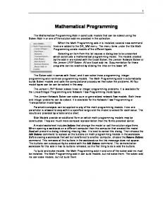
support. In Figure 3, an example of manual creation of a GAMS model for engineering problems is shown. In particular, note the manual duplication and unique variable naming required when using the same cylinder component again. In order to support the modeling and formulation of component sizing problems using mathematical programming, the use of the Systems Modeling Language (SysML) [33] is proposed. SysML is a general modeling language developed by the Object Management Group (OMG). Therefore, prior to discussing the proposed framework in Chapter 3, a brief introduction to SysML is provided in the next section. * To use the same cylinder model twice, a copy with unique names must be created. * There is no concept of objects, or model hierarchies, or reuse of the same model. * Cylinder Model 1 set cylinderCatalog1 / SAE-64508, SAE-64008, HMW-5008, PMC-5608 /; parameter boreDiameterData1 / SAE-64508 0.1143, SAE-64008 0.1016, HMW-5008 0.127, PMC-5608 0.1016 /; variable cylinder_f1, cylinder_bore1, cylinder_rod1, cylinder_portA_p1, cylinder_portB_p1; equation cylinder_f_eq1; cylinder_f_eq1.. cylinder_f1 =e= Pi*0.25*( (sqr(cylinder_bore1)*cylinder_portA_p1) - cylinder_portB_p1* (sqr(cylinder_bore1)-sqr(cylinder_rod1)) ); * Cylinder Model 2 set cylinderCatalog1 / SAE-64508, SAE-64008, HMW-5008, PMC-5608 /; parameter boreDiameterData1 / SAE-64508 0.1143, SAE-64008 0.1016, HMW-5008 0.127, PMC-5608 0.1016 /; variable cylinder_f1, cylinder_bore1, cylinder_rod1, cylinder_portA_p1, cylinder_portB_p1; equation cylinder_f_eq1; cylinder_f_eq1.. cylinder_f1 =e= Pi*0.25*( (sqr(cylinder_bore1)*cylinder_portA_p1) - cylinder_portB_p1* (sqr(cylinder_bore1)-sqr(cylinder_rod1)) ); model m /cylinder_f_eq1, cylinder_f_eq2/; solve m using minlp maximizing cylinder_f1; display cylinder_f1.l, cylinder_f2.l;
Figure 3 Example of manual input of GAMS model for an engineering problem. There is duplication of variables and equations, making it difficult to reuse a model. Also, variable naming must be unique
2.4 Introduction to SysML In order to familiarize the reader with the terminology used in this thesis, some general background is provided regarding the features of SysML. SysML is an extension 26
of the Unified Modeling Language (UML) [34], both of which have been standardized by the OMG. UML is widely used in software engineering and has been extended to support the modeling of systems of all types through SysML. The following are some of the common SysML entities used throughout this thesis. These descriptions are based on the book by Friedenthal et al. [15] and the SysML specification [33]. SysML Blocks: A block is the primary modeling unit in SysML. The analogous of a block in software engineering is a class. A block can be used to represent various parts of a system, such as a process, function, model, behavior or the system itself. Blocks can be combined together to form subsystems and systems that collectively describe the problem being modeled. In addition, blocks can contain other entities like properties and ports to describe the problem in more detail. Thus, blocks provide a modular way for a designer to represent the system in a decomposable manner. SysML Properties: SysML properties are an extension of UML properties and can be classified as value properties and part properties. Value properties are commonly used to specify variables while part properties are used to define local usages for a block within another block. This is similar to the concept of class definition versus class usage in objectoriented programming. This translates well for component sizing problems, in which systems can be decomposed using part properties and variables can be modeled using value properties. SysML Flow Ports:
27
In order to enable model reuse in SysML, ports are used to clearly define the interfaces through which information can be exchanged [33]. By connecting together the ports of different blocks, it is possible to model the flow between various parts of the system. Depending on the system being modeled, the concept of what flows can be different such as energy flow between components in energy-based system models. Stereotypes & Profiles: In order to customize SysML for a specific domain such as GAMS or fluid power, UML (and SysML) provide a construct known as a stereotype that can be used to extend existing SysML constructs like blocks and properties. A stereotype is more precise than the existing SysML entities. Stereotypes are organized within profiles, which represent a collection of customizations for a specific domain or application.
2.5 Summary Through a review of literature related to solving of component sizing problems and their representation, it is clear that the CSP approach is a powerful solving technique that can be used in a variety of problems. In particular, component sizing problems clearly fit within the framework of CSP-based solving. However, limitations in the expressivity of the current modeling capabilities of CSP tools such as GAMS limits it from being used to solve problems in engineering design such as component sizing. Consequently, the framework proposed in this thesis involves using a general modeling language such as SysML to extend the current modeling formalisms of GAMS in order to support a more efficient representation of component sizing problems. This framework is described in the next chapter.
28
CHAPTER 3 EXTENDING MATHEMATICAL PROGRAMMING USING SYSML In this chapter, the framework for representing and solving component sizing problems more efficiently using SysML and GAMS is presented. In this framework, SysML is used to extend current mathematical programming formalisms of GAMS in order to provide a designer with improved capabilities for modeling the component sizing problem to be solved. The actual solving of the problem is still done using the integrated solvers included in GAMS. In this research, the solver BARON is used to solve the problem after it has been modeled in SysML. This process is based on using the principles of Model Driven Software Development (MDSD) [45], which is commonly used in software engineering. This process involves the specification of metamodels, domain specific languages (DSLs) and automated model transformations. In particular, the process of representing the analysis knowledge related to component sizing in a form that is convenient to designers within SysML is presented. Along with capturing this analysis knowledge, the process of transforming such a representation into a form that can be solved by external solvers in GAMS is also discussed. In order to use the advantages of both languages (SysML and GAMS), a combination of DSLs and model transformations are used to create a consistent representation in both languages. The approach presented in this thesis involves the following steps: 1. Formal Capture of GAMS Domain Using Metamodels. 2. Representing GAMS Compliant Models in SysML using Profiles 3. Model Transformations to Support Hierarchical Object-Oriented Modeling
29
Each step is discussed in the following sections.
3.1 Formal Capture of GAMS Domain Using Metamodels In order to provide designers with improved capabilities for representing component sizing problems, SysML is used as a formal object-oriented modeling language, which can then be passed to GAMS and subsequently solved. This requires a different approach than when done in a single tool, e.g. entirely in GAMS. In a single tool, this process would be done through internal data-models (language compilers) that are customized for the particular software tool, such as the source code for GAMS. In order to integrate multiple tools a common metamodel is used, which describes the concepts that can appear in a valid model as well as represents the links between these concepts, such as inheritance and composition. To support such model and metamodel driven systems, the OMG established the Meta Object Facility (MOF) standard, which provides a framework for “defining, manipulating, and integrating meta-data and data in a platform independent manner” [23, 32]. A metamodel represents the abstract syntax for a domain, since the relations are defined using classes and associations that are independent of any particular encoding. To extend the functionality supported by GAMS, the approach taken is to convert the implicit metamodel for GAMS (i.e., the data structures used internally – refer Table 3) into a formal and explicit metamodel compliant with the MOF standard. In addition, existing constructs are extended through additional features such as object-oriented modeling that are added to the metamodel.
30
The GAMS metamodel is shown in Figure 4, in which the constructs in GAMS are represented as classes (GamsSolve, Model, GamsVariable, etc.). According to mathematical programming formalism of GAMS, the model that is passed to a solver consists only of equations and there is no concept of ownership. Moreover, a GAMS file consists of a number of variables, parameters, sets, equations, a model statement and a solve statement, and some display statements, all of which are modeled at the same level. As a result, a GAMS model is flat i.e., there is no concept of an object, ownership, or visibility (public, private). This lack of expressivity severely limits a designer’s ability to describe systems in terms of modular components. To overcome this, existing GAMS constructs are mapped to different objects (similar to class in object-oriented programming) in the metamodel shown in Figure 4. In order to introduce the concept of ownership and hierarchical modeling, associations are defined between the objects such as A_owner_ownedModels and A_model_variables. This enables a designer to define and limit the scope of GAMS constructs used within models. These associations can be described as follows. The GamsSolve corresponds to the solve statement in GAMS and it represents the top-most level in the resultant model hierarchy. Just as a solve statement specifies the model to solve, a GamsSolve object has an association A_gamsSolve_model which specifies that a GamsSolve object owns a Model. This is as far as the similarity between GAMS and the metamodel goes. Unlike GAMS, the metamodel allows a Model to own the following: other models, variables, sets, parameters and equations. In this way, it is possible for a designer knowing GAMS syntax to define a modular class-based system with object-oriented constructs.
31
Figure 4 GAMS Metamodel Definition. Semantics Of GAMS are Represented as Objects in the Metamodel An interesting feature of the metamodel described above is that it is not specific for component sizing problems. The abstract syntax described in this metamodel can be used to represent any GAMS model and can therefore be used for other applications as well that consist of decomposable systems. In order to provide additional capabilities specifically for component sizing, new language constructs are added to the concrete syntax, in this case SysML. This involves customizing SysML through the use of profiles, and then using model transformations to
32
automatically generate an executable representation in GAMS. The customization of SysML is discussed in the next section.
3.2 Representing Component Sizing Problems in SysML Since SysML is a general purpose modeling language, it lacks the detailed, formal semantics needed for representing a problem in a domain-specific way [4]. For instance, there is no SysML concept that can represent GAMS-specific semantics like variable or parameter. They could all be modeled by using the same SysML construct, such as Property, and using the name to represent a variable or parameter (e.g. variable_x as the name of a Property in SysML). This would lead to ambiguity at the time of converting from SysML to GAMS. In addition, the lack of precise problem-specific semantics can make it cumbersome for domain experts to create models in SysML due to the large amount of repetitive tasks involved. This can limit the acceptance of general SysML for specific domains and problems. Therefore, in order for SysML to be used for modeling a particular type of problem, the necessary semantics associated with the problem must be included within SysML through customizations. Therefore, in this section, the process of customizing SysML for component sizing is discussed. There are two parts to this: capturing existing GAMS semantics in SysML and defining new semantics that are relevant from a component sizing perspective.
33
3.2.1
Capturing GAMS Semantics in SysML Using Profiles SysML (UML) provides several mechanisms for customization, such as extending
the UML metamodel, creating new profiles that extend existing SysML/UML constructs or defining a completely new language. Profiles are preferred since they do not modify the underlying UML metamodel, thereby retaining existing tool support [47]. A portion of a profile created for representing component sizing problems based on GAMS semantics is shown in Figure 5. The profile is constructed as per the MOF metamodel (Figure 4). For instance variable, parameter and set each have their own stereotype defined but all extend the SysML Property class. The GAMS construct for equation is defined by a stereotype GamsEquation that extends the SysML Constraint class. Since both the model and solve constructs extend the SysML Block, all of the characteristic of a Block are available to objects stereotyped as GamsModel and GamsSolve. For instance, SysML supports hierarchical modeling through composition associations and this is automatically available when using GamsModel stereotype to create models.
34
pkg [Profile] GamsProfile[
GamsProfile ]
«stereotype» Block [Class]
Existing GAMS Semantics
«metaclass» Constraint
«stereotype» GamsSolve [Class]
«stereotype» GamsEquation [Constraint]
-isEncapsulated : Boolean [0..1]
«stereotype» GamsModel [Class]
-modelType : GamsModelType [1] = minlp -optimizeDirection : GamsOptimizeDirectionKind [1] = minimize -solverType : GamsSolverType [1] = BARON -objVarName : String [1] = null
-domainName : String
«metaclass» Property
«stereotype» GamsVariable [Property]
«stereotype» GamsSet [Property]
«stereotype» GamsParameter [Property]
-flowFlag : FlowFlag [1] = nonflow -domainName : String -type : GamsVariableType [1] = free
-specification : String [1] = "" -domain : ValueProperty [0..*] -domainName : String
-specification : String [1] -domainName : String
«metaclass» Port
«stereotype» OwnedGamsModel [Property]
«metaclass» Connector
«stereotype» GamsPort [Port]
«stereotype» GamsPhysicalConnection [Connector]
«stereotype» GamsSelectionConnection [Connector]
-causality : GamsCausality [1] = inout
«metaclass» Constraint
«stereotype» GamsPhysicalConnectionEquation [Constraint]
«stereotype» GamsSelectionConnectionEquation [Constraint]
New Semantics
Figure 5 Profile to extend Mathematical Programming semantics in SysML. New semantics are defined that extend from existing Port, Connector and Constraint metaclasses.
35
3.2.2
New Constructs in SysML to Support Representation of Component Sizing Problems Existing SysML constructs are extended using stereotypes to make it easier for a
designer to define component sizing problems. These new features include support for hierarchical modeling, embedding the physics related to energy-based systems that are typically encountered during engineering design, as well as support for explicitly defining dependencies between component models and their associated selection models (supplier catalogs). Hierarchical modeling is established through existing composition associations in SysML and this allows the designer to logically decompose a system into its individual components. It also enables a designer to store models and reuse them in multiple contexts in the same problem or across different problems. An important effect of modularization is the possibility of using connections to connect the components in different ways, which is similar to the process engineers use when assembling together components in the real world. The concept of connecting components exists at multiple levels during the design process. Moreover, the connections can have different meanings depending on the context in which they are used. For instance, when connections are used to create schematics they refer to the graphical representation. For this and other situations in which connections can be used, the existing SysML constructs of Port and Connector are customized depending on the context of use. Based on the different contexts, it is possible to encode knowledge by customizing SysML in order to make it more convenient for designers to formulate component sizing problems. This reduces the
36
amount of repetitive and error-prone manual modeling that a designer would otherwise have to do. In particular, three types of connections are considered in this research: 1. Connections used to describe a system architecture 2. Connections used for energy-based analysis models 3. Connections used to establish relations between multiple analysis models and corresponding catalog models In this research, a system architecture is assumed to exist and component sizing is performed on the given architecture. Therefore, the capability to model a system architecture by connecting components together is provided by customizing existing SysML constructs of Port and Connector. The additional knowledge that is encoded in Port and Connector can be used to automatically generate equations that a designer would otherwise have to manually define. A common feature in models for energy-based systems is the existence of standard interfaces through which energy is transferred between components. This process of energy transfer can be captured in terms of equations that can be used to generate system-level models from component-level models and their connections. This logic is based on the law of energy conservation and can generally be formulated through two equations: •
Sum-to-zero equation for flow variables (e.g. force, flow, torque)
•
Equality equation for potential variables (e.g. pressure, velocity, angular speed).
This is a generic logic that applies to multiple domains including fluid power, mechanics (translational / rotational), thermal, etc. Therefore, to aid the designer in
37
creating system-level analysis models from component models, Port and Connector are
customized
to
encode
this
logic
for
energy
transfer
(refer
to
stereotype in the GAMS profile in Figure 5). This allows for automatic generation of equations, which would otherwise be done manually by the designer. As a result, it is easier for designers to create new architectures and analyze them. The final type of connection that is customized refers to the process of relating a component to its use across multiple analyses. As discussed previously, component sizing involves satisfying a number of requirements simultaneously. These requirements come from multiple analyses such as cost analysis, mass analysis, and hydraulic performance analysis. Different component models exist for each analysis and therefore it is necessary to ensure that ultimately the same component is referred to across all of the analyses. This is done by defining a SystemSizingModel, in which all of the components to be sized are included, and then explicitly defining connections between each component in the SystemSizingModel and its usage in each analysis model. The Connector class is extended through the stereotype. The corresponding logic to be encoded involves the creation of equality constraints between each variable in the component model in SystemSizingModel and its corresponding usage in an analysis.
Thus, by defining current GAMS semantics along with new constructs related to component sizing problems in SysML, a designer is provided with additional capabilities to represent component sizing problems. Moreover, the combination of profiles and
38
metamodels provides the framework in which model transformations can be used to define the logic described above in order to automatically generate models that can be solved in GAMS. This is discussed in the next section.
3.3 Model Transformations to Support Hierarchical Object-Oriented Modeling As discussed in the previous sections, a combination of profiles and metamodels are used to provide new capabilities to designers for representing component sizing problems in SysML and solving them by solvers in GAMS. In order to encode the logic behind these new constructs (such as ) as well as generate GAMS-compliant executable code, model transformations are used to automatically perform these tasks. Model transformations are used to convert the SysML model into an intermediate object-oriented GAMS model, which is then transformed into a flat executable model that can be solved within GAMS. Since the domain MOF metamodel and SysML profile can be described in terms of graphs [1], model transformations can be defined in which the domain semantics (metamodel and profile objects) represent the nodes, and associations between objects represent the edges. As is shown in Figure 6, the transformations are defined in a declarative fashion at the meta-model level and are then compiled into an executable form that operate at the user-model level.
39
Source Metamodel
Refers to
Transformation Definition
Conforms to
Refers to
Executes Reads
Source View
Target Metamodel Conforms to
Writes Transformation
Target View
Figure 6 Process Of Model Transformation from Source to Target Model (Czarnecki et al. [8]) A correspondence metamodel is used to maintain relations between the elements of the input SysML model and the resulting GAMS model [23, 44]. This is necessary when retrieving information from the solver's output to update the SysML model. An example of a correspondence link is shown in the correspondence metamodel in Figure 7. It
involves
the
use
of
object
GamsModelUsage2GamsModelPartProperty
gmu2gmpp to
of
type
link
a
topLevelGamsModelPartProp object of type Property in SysML to a topLevelGamsModel object of type GamsModel in the GAMS metamodel (refer to the GAMS metamodel in Figure 4).
40
GAMS Metamodel
Correspondence Metamodel
SysML Metamodel
Figure 7 Portion of correspondence metamodel defined to relate SysML and GAMS metamodels Model transformations are then defined using the correspondence metamodel to relate elements of the source and target views with one another. The transformations are written in a declarative and graphical manner through the use of story diagrams [13]. The model transformations used in this research are defined in MOFLON [27], which automatically generates Java Metadata Interface (JMI) code that implements the transformations in Java. This JMI code is then combined with a JMI-compliant SysML tool, such as Magic Draw [30], in the form of a plugin that can be executed from within SysML. The sequence of model transformations executed to solve a component sizing problem described in SysML using solvers in GAMS is shown in a SysML activity diagram (Figure 8). Each action represents a transformation that is performed.
41
SysML Activity Diagram [
XformSequence ]
Solve Block in SysML Generate Physical Connection Equations
Operate on SysML Model
Generate Sizing Connection Equations
Transformation to Convert SysML Model to MOF Model (as per GAMS Metamodel)
Operate on MOF model
Transformation to Convert MOF Model to Flattened MOF Model
Print Flattened Model into a GAMS executable text file
Execute Model using Solvers in GAMS
Pretty Printing to text file
Update SysML Model with Results
Figure 8 Sequence of Model Transformations to solve the component sizing problem. Converts from SysML model to GAMS executable model and returns output of solver to SysML The transformation that converts an input SysML model of the problem into an intermediate representation based on the MOF metamodel is shown in Figure 9. One such transformation is shown in, in which the input is a SysML block (stereotyped with GamsSolve) that contains solver information and the model to be solved. The output of this model transformation is the creation of an equivalent model based on the GAMS metamodel that was defined previously. The mechanism for transformation involves matching a pattern (left-hand side) and applying a replacement pattern (right-hand side) if successful. The pattern to be matched is defined in black and the replacement pattern is shown in green (with tag visible).
42
Figure 9 Model Transformation to convert SysML model to MOF model (as per GAMS Metamodel)
43
3.4 Summary In this chapter, a framework using Model-Driven Software Development concepts is presented for representing component sizing problems in SysML and their solving in GAMS. This framework provides improved capabilities to designers for more efficiently formulating component sizing problems in a hierarchical, model-based manner, thereby addressing the limitations of current tools in terms of expressivity. Moreover, the use of SysML enables this framework to be integrated within larger frameworks of design, such as Model-Based Systems Engineering. In the next chapter, an example application is presented which explores the use of this framework for representing and solving component sizing problems more efficiently.
44
CHAPTER 4 EXAMPLE APPLICATION: COMPONENT SIZING FOR A HYDRAULIC LOG SPLITTER In this chapter, an example application involving the sizing of a hydraulic log splitter is presented in order to apply the framework presented in this research. First, the motivation for the use of fluid power as an example domain is provided. Thereafter, the modeling of the problem in SysML using the proposed framework is discussed. Finally, results obtained from solving the problem under different scenarios are presented.
4.1 Problem Description and Motivation for Fluid Power To validate the framework presented in the previous chapter for automated component sizing, it is applied to an example belonging to the fluid power domain. The use of fluid power as an example domain for component sizing was discussed in Section 1.3. To summarize, some of the desirable characteristics of the fluid power domain include: systems are circuit-like in that they can be modularized and connected together, well defined interfaces exist between components, and there is large amount of catalog data available for different components which makes component sizing problems combinatorially hard to solve. . The hydraulic system considered in this example application is that of a horizontal acting hydraulic log splitter (Figure 10). A log splitter is a system used to divide roughly cylindrical pieces of wood into two or more pieces, generally longitudinally along the grain of the wood. An operator loads a piece of wood (of varying length) and actuates a
45
control to drive a wedge along the grain of the wood. Log splitters are usually portable and so the critical requirements include the ram force available to split the log, total cycle time involved, total mass, and total cost of the machine. These attributes represent competing objectives, out of which the designer must make tradeoffs to find a specification that satisfies all of the requirements simultaneously. Log Loading & Splitting Area
Directional Control Valve
Hydraulic Cylinder & Ram Engine & Pump
Engine
Pump
Directional Control Valve
Tank
Cylinder
Load
Hydraulic Connection Mechanical Rotational Connection Mechanical Translational Connection
(credit: Dave Thompson)
Figure 10 An assembly and block diagram for a horizontal acting hydraulic log splitter The scope of component sizing is limited to the hydraulic subsystem; the mechanical structure is not considered. In Figure 10, a block diagram of the log splitter architecture considered in this example application is shown. There are different system architectures that can be used, for instance open center circuit with constant pump displacement versus closed center circuit with variable pump displacement. In this example, the open-center circuit is used. The components that are considered include: a gas engine, hydraulic fixed displacement pump, directional control valve, double acting cylinder, load and tank. Since the system is horizontal, only a horizontal load requirement is considered. As discussed in Chapter 1, this example is restricted to a single architecture for which component sizing is to be performed.
46
The log splitter problem is a valid example for the proposed framework because it possesses characteristics that belong to larger and more complex models. This includes the presence of multiple types of interfaces (hydraulic, translational, rotational), competing objectives (minimize cost versus maximize force), as well as multiple types of analyses (cost, mass, fluid power performance). In this example, four components – engine, pump, cylinder and valve – are considered for sizing, and their possible sizes are taken from component catalog information that has been obtained from industrial component manufacturers. In the following sections, the modeling of the log splitter in SysML and its subsequent solving in GAMS is discussed.
4.2 Modeling the Log Splitter Problem in SysML As described in the previous section, the log splitter possesses different aspects that are commonly found in component sizing problems. From a designer’s perspective, the modeling steps that would be involved are as follows. The first step involves the specification of requirements and their relation to a particular component or variable. Since a single architecture is considered, the descriptive modeling step is not considered in which the architecture to be sized is modeled. This is discussed more in the Future Work section in the next chapter. Thereafter, the modeling of hydraulic performance is considered in which energy-based modeling principles are used. As part of the hydraulic performance analysis, the designer needs to consider multiple use-phases based on the problem requirements. After modeling the hydraulic performance with multiple use phases, other types of analyses are modeled. Finally, in
47
order to ensure that all of the analyses and use phases are considered simultaneously the designer needs to ensure that a common sizing for each component is used throughout the entire model and is associated with one catalog model. In order to evaluate the usefulness of the proposed framework, each aspect is discussed separately in the same order that the designer would approach the modeling task without a framework.
4.2.1
Requirements Modeling in SysML One of the features of SysML is the ability to model requirements and assign
dependencies between requirements and model elements. In the case of component sizing, requirements modeling is the first step for guiding the designer in defining the composition of the system in terms of relevant analyses as well as the mathematical constraints associated with the requirements. In Figure 11, a SysML requirements model is shown in which requirements are decomposed hierarchically until they can be described mathematically. For instance, the forward phase for the hydraulic analysis consists of two requirements: a.) The force produced by the cylinder should be greater than a specified limit and b.) The maximum pressure in the circuit should be less than the specified max pressure. In this way, requirements modeling helps to derive mathematical constraints that are then included in the different SysML analysis models, which is described in the next section.
48
Figure 11 SysML model for requirements and associating them with corresponding component models through dependencies (). Requirements modeling helps to decompose the problem into different analyses and use phases.
49
parts
«GamsSolve» Solve
«verify»
LogSplitterReq ]
{flowFlag = nonflow , type = free}
z
{flowFlag = nonflow , type = free}
totalMass : GamsFree
massAnalysis : MassAnalysis
{flowFlag = nonflow , type = free}
totalCost : GamsFree
«requirement» Cost
Id = "2.3" Text = "Total cost shall be less than $1000 "
{flowFlag = nonflow , type = free}
Fl
load : Load
oc : OpenCenterCkt
forward : ForwardAnalysis
{flowFlag = nonflow , type = free}
totalTime : GamsFree
reverse : ReverseAnalysis
fpAnalysis : FPAnalysis
systemLevelModel : SystemLevelModel
costAnalysis : CostAnalysis
«requirement» TotalSystem
Id = "2" Text = " "
systemLevelModel : SystemLevelModel{Verifies = TotalSystem}
«verify»
Id = "2.2" Text = "Total mass shall be less than 300 kg "
«requirement» Mass
req [Package] Requirements [
«deriveReqt»
«verify»
Id = "2.1.1.2" Text = "System pressure shall be less than 3e7 Pa "
Id = "2.1" Text = " "
«deriveReqt»
Id = "2.1.1.1" Text = "Force shall be greater than 10000 N"
«requirement» ForceF
Id = "2.1.1" Text = " "
«requirement» Forward Phase
«deriveReqt»
«requirement» PrF
«verify»
Id = "2.1.3" Text = "Total cycle time shall be less than 20 s "
«requirement» CycleTime
«verify»
Id = "2.1.2.1" Text = "Force shall be greater than 1000 N in negative direction "
«requirement» ForceR
«deriveReqt»
Id = "2.1.2" Text = " "
Id = "2.1.2.2" Text = "System pressure shall be less than 3e7 Pa "
«requirement» PrR
«deriveReqt»
«requirement» Reverse Phase
Requirements Decomposition
«requirement» HydraulicSystem
Associating Requirements with Models through dependencies ()
Before discussing the details of the SysML models used to formulate the sizing problem, the overall system model is shown in Figure 12. The details of these models (such as constraints) have been hidden to allow the reader to understand the overall model hierarchy that is common to general component sizing problems. bdd [Package] LogSplitterProblem[
SystemLevelView ]
Common Sizing Across Entire Model
«GamsSolve» Solve
Solve Block
«GamsSolve»
modelType = minlp objVarName = "massAnalysis.totalMass" optimizeDirection = minimize solverType = BARON
«gamsModel» SystemSizingDescription parts
«OwnedGamsModel» -systemLevelModel
«gamsModel» SystemLevelModel values
«GamsVariable»z
«OwnedGamsModel» -massAnalysis
«OwnedGamsModel»pump : PumpSizing «OwnedGamsModel»cylinder : CylinderSizing «OwnedGamsModel»engine : EngineSizing «OwnedGamsModel» «OwnedGamsModel»cylinderCat : CylinderCat -systemSizing «OwnedGamsModel»engineCat : EngineCat «OwnedGamsModel»pumpCat : PumpCat «OwnedGamsModel»valveCat : DCValveCat «OwnedGamsModel»valve : ValveSizing
«OwnedGamsModel» -costAnalysis
«OwnedGamsModel» -fpAnalysis
«gamsModel» MassAnalysis
«gamsModel» CostAnalysis
parts
parts
«OwnedGamsModel»cylinder : CylinderMass «OwnedGamsModel»pump : PumpMass «OwnedGamsModel»valve : ValveMass «OwnedGamsModel»tank : TankMass «OwnedGamsModel»engine : EngineMass
«OwnedGamsModel»cylinder : CylinderCost «OwnedGamsModel»pump : PumpCost «OwnedGamsModel»tank : TankCost «OwnedGamsModel»valve : ValveCost «OwnedGamsModel»engine : EngineCost
values
«GamsVariable»totalMass : GamsFree
«gamsModel» FPAnalysis
values
«GamsVariable»totalCost : GamsFree
values
«GamsVariable»totalTime : GamsFree
«OwnedGamsModel» -reverse
«gamsModel» ReverseAnalysis
«OwnedGamsModel» -oc
Multiple Analyses
Multiple Use-Phases
«OwnedGamsModel» -forward
«gamsModel» ForwardAnalysis
«OwnedGamsModel» -oc
«gamsModel» OpenCenterCkt parts
«OwnedGamsModel»cylinder : CylinderFP «OwnedGamsModel»pump : PumpFP «OwnedGamsModel»tank : TankFP «OwnedGamsModel»valve : ValveFP «OwnedGamsModel»engine : EngineFP «OwnedGamsModel»fixed : FixedFP «OwnedGamsModel»load : Load
Energy-Based Modeling
Figure 12 System Level View highlighting the features found in component sizing problems. This type of model hierarchy would be common for such problems in general.
50
4.2.2
Energy-Based Modeling & Multiple Use-Phases for Fluid Power Systems In order to analyze the hydraulic performance and ensure that the requirements
are satisfied, algebraic equations are used to model the behavior of the individual hydraulic components as well as the combined system behavior. Since algebraic equations are used instead of dynamic simulations, steady state behavior is assumed for the system. Assuming a single steady state operation for a problem is not feasible and therefore multiple use-phases are considered, each representing a particular steady state phase. In the case of the log splitter, two use-phases are considered: the forward motion of the wedge and the reverse motion of the wedge. These two phases can be assumed to occur at constant velocity and therefore the steady state equations can be used. In Figure 13, a portion of the SysML model is shown in which the same hydraulic circuit is used for two phases. For more complex problems, it is possible to discretize the system into a number of time-steps, each of which can be assumed to operate at steady state. This is discussed further in the section on Future Work in the next chapter.
51
bdd [Package] LogSplitterProblem [
UsePhases ]
«gamsModel» FPAnalysis {totalTime =e= forward.oc.cylinder.time + reverse.oc.cylinder.time, totalTime =l= 20, totalTime =g= 0.001} values
totalTime : GamsFree{flowFlag = nonflow, type = free}
«OwnedGamsModel» -forward
«OwnedGamsModel» -reverse
«gamsModel» ForwardAnalysis {oc.load.Fl =g= 50000, oc.cylinder.length =g= 0.25, oc.valve.control =e= 1}
«OwnedGamsModel» -oc
«gamsModel» ReverseAnalysis {oc.load.Fl =l= -1000, oc.cylinder.length =l= -0.25, oc.valve.control =e= 0}
«OwnedGamsModel» -oc
«gamsModel» OpenCenterCkt {pump.portP.p =e= valve.portP.p, pump.portP.q + valve.portP.q =e= 0, pump.portT.p =e= tank.portP.p, pump.portT.q + tank.portP.q =e= 0, valve.portT.p =e= tank.portT.p, valve.portT.q + tank.portT.q =e= 0, valve.portA.p =e= cylinder.portA.p, valve.portA.q + cylinder.portA.q =e= 0, valve.portB.p =e= cylinder.portB.p, valve.portB.q + cylinder.portB.q =e= 0, engine.flange.w =e= pump.flange.w, engine.flange.tau + pump.flange.tau =e= 0, cylinder.flangeA.v =e= fixed.flange.v, cylinder.flangeA.f + fixed.flange.f =e= 0, cylinder.flangeB.v =e= load.flange.v, cylinder.flangeB.f + load.flange.f =e= 0} parts cylinder : CylinderFP pump : PumpFP tank : TankFP valve : ValveFP engine : EngineFP fixed : FixedFP load : Load{Verifies = ForceF}
Figure 13 Modeling multiple use-phases for a problem. In this case, there are two usephases, a ForwardAnalysis and ReverseAnalysis. The use-phases are for the same hydraulic circuit, as represented by the common OpenCenterCkt Block. Energy-based modeling principles are used to define analysis models for a particular use-phase. This is used when connecting individual component models together to form a system level model of the fluid power circuit. In Figure 14, an Internal Block Diagram (IBD) for the hydraulic circuit is shown. Through the use of transformations to automatically generate equations based on the connections between components, it is possible to generate complete analysis models by combining individual 52
components and connecting them together. Energy-based principles are used when connecting components as well as at the time of defining individual component behavior. Through the use of proper sign conventions and standardized port-based interfaces, it is possible to define components that can potentially be reused in other problems as well. Component models and the sign conventions used are described in Appendix A. ibd [gamsModel] OpenCenterCkt[ fixed : FixedFP
OpenCenterCkt ]
flange : TransConnectorFP
flangeA : TransConnectorFP
cylinder : CylinderFP
portP : FluidConnectorFP
load : Load flangeB
«GamsPhysicalConnection»
valve : ValveFP
portA
portA «GamsPhysicalConnection»
portB
flange
«GamsPhysicalConnection»
«GamsPhysicalConnection» portP : FluidConnectorFP
portB «GamsPhysicalConnection»
pump : PumpFP portT
portT flange : RotConnectorFP
«GamsPhysicalConnection»
portT
«GamsPhysicalConnection» flange : RotConnectorFP
«GamsPhysicalConnection»
portP
tank : TankFP
engine : EngineFP
Figure 14 A Internal Block Diagram for the open center circuit used in the problem. The connections between ports are stereotyped with and automatically generate the connection equations, based on conservation of energy. Along with the energy-based analysis such as hydraulic performance, there are also other types of analyses that are needed to determine if requirements are satisfied. The modeling of multiple analyses and organizing them in a model hierarchy is discussed in the next section.
4.2.3
Multiple Analyses & Hierarchical Modeling In addition to energy-based analyses such as fluid power performance, other
analyses are also needed depending on the requirements specified by the designer. For
53
instance, the requirement on total mass and total cost of the system cannot be included within the analysis described in the previous section, because defining cost in multiple use-phases does not make sense from a modeling perspective and would also result in duplication of the same constraint, resulting in model ambiguity. Different analyses can be modeled in the same way as energy-based analyses and can be arranged in a model hierarchy under a single top-level model. By grouping the analyses under a common model, it is ensured that the resultant executable model contains all of the different analyses and, if applicable, multiple use-phases (see cost, mass and fluid power analysis all acting simultaneously in Figure 12). In this way, hierarchical modeling in SysML can be used to model the component sizing problem in a logical and modular fashion using individual component models that can be reused in the same problem or in different problems. It is important to note that each analysis and use-phase uses different (or duplicate) component models to ensure that there is no overlap in variable usage. However, since all of the analyses and use-phases are supposed to involve the same components, a mechanism is needed in SysML to define the relations between a component sizing model and its multiple usages across analyses and use-phases. This is discussed in the next section.
4.2.4
Common Sizing Description for the Entire Model When a problem is divided into different analyses and use-phases that exist
independently of each other, it is important to remember that sizing is determined by considering all of the analyses simultaneously. However, since each analysis and usephase model use different usages for the same component model, it is necessary to
54
establish a relation between all of the usages throughout the model. For instance, the forward and reverse use phases and the mass and cost analyses each use a different cylinder model that has all of the sizing variables. From a systems perspective, the selection of the Cylinder depends on all the analyses. Therefore, to ensure that the same sizing variable is referred to throughout the different analyses and use-phases, a separate system sizing model is defined that contains the sizing variables used throughout the system (SystemSizingDescription – see Figure 12). There are two main reasons for using a system sizing model: a. Specifying a component model and its associated catalog model once for the entire problem, irrespective of the number of use-phases or analyses (see the component catalog library in Figure 15) b. Ensuring that all analyses and use-phases refer to the appropriate component model by explicitly connecting the component model with its usages in each analysis and use-phase. (see Figure 17) In order to specify the sizes a component can assume, a two-step process is used, in which first a catalog model is populated with data and then equations are defined to ensure that the sizing variables only take values from the catalog model. By storing supplier data in a problem-independent model library, it is possible to populate a component catalog model, which is problem-specific, with possible component values by establishing dependencies between the sizing variables used in the problem with the corresponding parameters (constants) found in the model library. Model transformations are used to automatically populate the component model with information found from the model library (see Figure 15).
55
bdd [Package] LogSplitterProblem [
Sizing Description Model for Problem
ValveCatalog ]
«GamsSolve» Solve
Component Catalog Library
«OwnedGamsModel» -systemLevelModel
«gamsModel» SystemLevelModel parts
fpAnalysis : FPAnalysis{Verifies = CycleTime} costAnalysis : CostAnalysis{Verifies = Cost} massAnalysis : MassAnalysis{Verifies = Mass} values
z{flowFlag = nonflow, type = free}
«OwnedGamsModel» -systemSizing
Possible Values for Cost of Valve
«gamsModel» SystemSizingDescription parts
pump : PumpSizing cylinder : CylinderSizing engine : EngineSizing cylinderCat : CylinderCat engineCat : EngineCat pumpCat : PumpCat valve : ValveSizing
Valve Catalog Model «OwnedGamsModel» -valveCat
«gamsModel» DCValveCat values
Automatically Populate Values from Library
id select : GamsBinary maxFlowCatData costCatData maxPressureCatData massCatData
Figure 15 The process of using a problem-independent component catalog library to automatically populate the possible values (in this example, cost of a valve) into the catalog model being used in the problem After defining the catalog model, constraints are defined to ensure that sizing variables for a component assume values only from the set of possible values contained in the catalog model. For instance, it is not meaningful for a cylinder to have sizing variables like: boreDiameter = 0.3m, stroke = 1m, mass = 1kg, cost = $10 because it is physically impossible. Therefore, a Boolean variable is used to determine which component from the catalog has actually been selected. An example of the collection of equations used for a cylinder is provided in Figure 16. In this way, it is possible to ensure that all of the sizing variables take values from a particular catalog entry.
56
bdd [Package] LogSplitterProblem [
CylinderSelection ]
«gamsModel» SystemSizingDescription parts
pump : PumpSizing engine : EngineSizing engineCat : EngineCat pumpCat : PumpCat valveCat : DCValveCat valve : ValveSizing
«OwnedGamsModel» -cylinder
«OwnedGamsModel» -cylinderCat
«gamsModel» CylinderSizing
«gamsModel» CylinderCat
values
boreDiameter strokeLength mass cost maxPressure rodDiameter
Sizing Variables
values
id select : GamsBinary boreDiameterCatData costCatData maxPressureCatData strokeLengthCatData massCatData
Possible Values from Catalog
Equation in SystemSizingDescription: cylinder.boreDiameter = sum(cylinderCat.id, cylinderCat.select(cylinderCat.id) * cylinderCat.boreDiameterCatData(cylinderCat.id)) where: cylinderCat.id �set of all cylinder components in the catalog library cylinderCat.select(cylinderCat.id) �binary variable defined over set cylinderCat.id. One binary variable for each component in the catalog set. But only one value is 1, all else are 0, as given by the equation: sum(cylinderCat.id, cylinderCat.select(cylinderCat.id)) = 1. cylinder.boreDiameter � sizing variable. Can assume a value from the catalog cylinderCat.boreDiameterCatData � possible values of bore diameter (from catalog)
Figure 16 Equations used to associate a component’s sizing variables (boreDiameter) with the corresponding catalog values from supplier (boreDiameterCatData) The equations above involve the use of a binary variable (0 or 1) that is defined over the set of all possible components. From the summation equation (sum(cylinderCat.id, cylinderCat.select(cylinderCat.id)) = 1),
only one of the binary values in the entire set can be 1
and this represents the component that is selected by the solver. After defining the relation between component and catalog connections are defined
(stereotyped
with
)
between
the
component models in the system sizing model with the component models used in the analyses (see Figure 17). Based on the model transformation logic defined in the framework, constraints are automatically generated for all of the variables included at 57
each end of the connection, since both ends of the connection refer to the same sizing model. In Figure 17, an example of such a constraint is shown in the SystemLevelModel Block in which the bore diameter in the forward phase is equated to the bore diameter in the system sizing model. ibd [gamsModel] SystemLevelModel[
SystemLevelModel ] systemSizing : SystemSizingDescription
«GamsSelectionConnection»
pump : PumpSizing
cylinder : CylinderSizing
costAnalysis : CostAnalysis pump : PumpCost
cylinder : CylinderCost
size : PumpSizing
size : CylinderSizing
«GamsSelectionConnection»
«GamsSelectionConnection» massAnalysis : MassAnalysis pump : PumpMass size : PumpSizing
cylinder : CylinderMass «GamsSelectionConnection»
size : CylinderSizing
«GamsSelectionConnection» «GamsSelectionConnection» fpAnalysis : FPAnalysis forward : ForwardAnalysis
bdd [Package] LogSplitterProblem [
oc : OpenCenterCkt pump : PumpFP size : PumpSizing
cylinder : CylinderFP size : CylinderSizing
SystemSizing ] «gamsModel»
SystemLevelModel1 «GamsSelectionConnection» {systemSizing.cylinder.boreDiameter =e= fpAnalysis.forward.oc.cylinder.size.boreDiameter, systemSizing.cylinder.cost =e= fpAnalysis.forward.oc.cylinder.size.cost, systemSizing.cylinder.mass =e= fpAnalysis.forward.oc.cylinder.size.mass, systemSizing.cylinder.maxPressure =e= fpAnalysis.forward.oc.cylinder.size.maxPressure, systemSizing.cylinder.rodDiameter =e= fpAnalysis.forward.oc.cylinder.size.rodDiameter, systemSizing.cylinder.strokeLength =e= fpAnalysis.forward.oc.cylinder.size.strokeLength}
reverse : ReverseAnalysis oc : OpenCenterCkt pump : PumpFP size : PumpSizing
cylinder : CylinderFP «GamsSelectionConnection»
size : CylinderSizing
Automatic Generation of Constraints from Connection
Figure 17 Through the use of a customized connection (), it is possible to ensure that common sizing description is used across the entire model. Equations are automatically generated to equate the variable used in an analysis or use-phase with the corresponding variable in the sizing description model.
58
4.2.5
Defining the Solve Block & Solving in GAMS Once all the analysis models have been defined along with a system sizing model,
it is possible to define a Solve Block of stereotype that specifies solver related properties such as solver name, model type, objective variable and so on. After the top-level SystemLevelModel Block of stereotype is connected with the Solve block, the next step is to execute the model transformations in the form of a plugin (refer to Section 3.3) in order to solve the problem externally in GAMS. In this way, a complete component sizing model for the log splitter is constructed in SysML. Then, through model transformations, executable GAMS code is generated that can be solved using the solver specified in the SysML model. The results obtained from this model are discussed in the next section.
4.3 Results for Different Scenarios In this section, results obtained from solving the log splitter component sizing problem for different scenarios are presented. As discussed in the Introduction, the motivation for this research is the investigation of new frameworks that can represent and solve component sizing problems more efficiently. Therefore, in addition to describing the actual solutions obtained for various scenarios, a discussion is provided regarding the use of SysML versus other tools such as MATLAB or GAMS. In the current scope of this research, investigation into the global optimality of solutions is not considered; such validation is beyond the current scope of this research and is left for future work.
59
Based on available component catalog data, sizing was performed on four components: a gas engine with 45 possible options, a fixed displacement pump with 64 possible options, a double acting cylinder with 158 possible options, and an open center directional control valve with 34 possible options. Depending on the constraints defined by the requirements as well as the variable to be “optimized”, the component selections obtained are different. The global MINLP solver BARON [39] in GAMS is used to solve the log splitter problem. Figure 18 lists a summary of the model and solution statistics for one scenario as provided by BARON. The model statistics remain the same for all scenarios, since they are only a variation of the problem. These statistics are useful in evaluating the complexity of the problem from a solver’s perspective. In this case, there are 68 nonlinear coefficient entries, 256 equations and 298 discrete variables (representing the catalog components). The code length of 503 provides some indication of the complexity of the nonlinearity of the model and represents the amount of code that GAMS passes onto the non-linear solver (For more information, refer to GAMS User Guide, Ch. 10 [3]). An important aspect to note is that the component models used in this example do not consider losses such as leakage or friction, i.e. they model ideal physical behavior. This assumption has been made because these models represent the first time that GAMS-compliant declarative models have been used. Since losses do not alter the fundamental behavior of the component, including them will only serve to make the model more complex, but will not invalidate the use of GAMS for solving of this class of problems.
60
Figure 18 Model and solver statistics for the scenario of minimizing total cost. The model statistics are same for all scenarios since they are for the same problem. The solution is provided by the solver BARON. Five scenarios are considered: maximizing the cylinder force during the forward phase, minimizing total cost, minimizing total mass, minimizing total time, and minimizing a variable that is defined by a multi-objective function. The requirements imposed on the system, in terms of constraints, are shown in Equation 3. These requirements act in addition to the constraints already imposed by individual component behavior models (see Appendix A for details of component models). Force produced in forward phase: ܨೝೢೌೝ ≥ 50,000 N Total time taken by system: ݐ௧௧ ≤ 20 s Total Cost of Components: ܥ௧௧ ≤ $1,000 Total Mass of Components: ݉௧௧ ≤ 150 kg
61
(3)
In order to understand the results obtained for the scenarios, it is necessary to identify the coupling between the different components of the log splitter. The log splitter’s function is to split wood by using force generated by a cylinder. The force produced by a cylinder directly depends on the bore diameter and pressure of the fluid inside it. Therefore, to produce more force, either the bore diameter or pressure can increase or both. Higher pressure at the cylinder means that the pump needs a greater input torque, which places a demand on the engine for higher torque. An increase in the bore diameter results in a decrease in flow rate in the cylinder, which increases the time taken to split the wood. Moreover, the maximum flow that can be handled by the system is limited by the valve that is used. Thus, with inequalities in the constraints it is difficult to determine manually what the best solution is to a given scenario. Before discussing the individual scenarios, provides an overall comparison of the results obtained. It appears that the results are appropriate, since the objective to be optimized in each scenario is better (smaller or larger, depending on optimization direction) than its corresponding value in the other scenarios. In addition to the overall results, the actual component sizes for each scenario are also described below, along with a discussion to understand the logic behind the values obtained.
62
Table 4 Comparison of results for different scenarios. Component Sizing is represented in terms of the selection from the corresponding component catalogs. Component Sizing (Selection Id from Catalog)
Selected Variable Values
Scenario
z
CPU Execution Time (s)
Cylinder Id
Pump Id
Engine Id
Valve Id
Maximize Force (N)
HMW-5032
SKP1NN_012
DP340E
NT-2020
139,833
94.9
993.5
20
0.4027
2.82
Minimize Total Time (s)
HMW-3010
SKP1NN_012
DP390E
NT_Prince2036
50,000
51.87
843.97
4.896
0.2529
3.54
Minimize Total Cost ($)
HMW-4010
SKP1NN_012
DP240
NT-2020
53,698
51.3
657.4
9.69
0.26116
2.45
Minimize Total Mass (kg)
PMC-5414
SNP2NN_4_0
DP160V
MSCDirect01825629
52,013
32.25
708.6
9.15
0.2528
78.13
Minimize HMW-5010 Multiobjective z
SKP1NN_012
DP390
NT-2020
147,437
71.53
866.3
13.79
-0.3968
5.65
z = 0.25*((totalMass/300) + (totalTime/20) + (totalCost/1000) - (forwardForce/50000))
63
Total Total Mass (kg) Cost ($)
Total Time (s)
Forward Force (N)
Maximize Force Produced by Cylinder in Forward Phase: In this scenario, the problem is to find the sizes for the components so that the maximum force can be produced to split the log, which is the force produced in the forward phase. The component sizes obtained are presented in Table 5. Table 5 Component Sizes to Produce Maximum Log Splitting Force (N) Bore Diameter (m) Stroke Length (m) Cylinder: Max Operating Pressure (Pa) HMW-5032 Cost ($) Mass (kg)
0.13 0.81 17200000 293.5 56.1
Displacement (m3/rev) Max Operating Pressure (Pa) Pump: Max Operating Speed (rpm) SKP1NN_012 Cost ($) Mass (kg)
1.1995E-05 11997000 2000 230 1.65
Max Torque (N-m) Speed at Max Torque (rpm) Engine: Max Power (W) DP340E Speed at Max Power (rpm) Cost ($) Mass (kg)
23.4 2500 8200 3600 399.99 32.65
Max Flow (m3/s) Valve: Max Operating Pressure (Pa) NT-2020 Cost ($) Mass (kg)
0.0016 1.38E+07 70 4.53
Since this scenario only cares about maximizing force, it is logical to assume that the other requirements (Equation 3) would remain at the bounds. The cylinder selected has a large bore diameter, resulting in greater force but increasing the time taken to complete one cycle. This is reflected in the total time lying at the boundary of the constraint, i.e. 20s. Similarly, the total cost ($993) is very close to the boundary of the constraint on total cost ($1000). The large bore diameter results in smaller flow for the same pressure and in this case it is only 0.0004 m3/s. Therefore, the consideration for valve selection lies mainly on the cost in order to maintain a total cost below the requirement. Since the objective is to maximize force, the possibility is to increase bore diameter and increase the pressure. The increase in bore diameter has been taken into account by selecting a large size cylinder. Higher system pressure is possible if the input torque to pump is higher, which leads to engines with higher possible torques. The logic underlying the selection of engine and pump is shown in Figure 19.
64
Engine Model: DP340E 25 Max Op. Speed for Pump (2010 rpm) Max Torque Point (from engine spec)
Engine Torque in N-m
20
15
Determined by solver: Operating Point of Engine in Forward Phase (21 N-m @ 2010 rpm)
Max Power Point (from engine spec)
Feasible engine operation region (under the solid curve)
10
5
0 500
Feasible pump operation region (left of the dashed line)
1000
1500
2000
2500 3000 Speed in rpm
3500
4000
4500
Figure 19 Engine operating point for forward phase of operation, as determined by solver. The operating point is below the speed at max torque (as provided by engine specification), which is counterintuitive to a designer
In Figure 19 the torque-speed curve for the engine selected by the solver is shown, in which the region below the curve represents the feasible operating region of the engine. A clarification regarding the position of the max torque point is required: the curve represents a quadratic curve fitted through the two operating points specified by the vendor (see Appendix for more details). Also shown is the maximum operating speed for the selected pump (red dashed line). Therefore, based on the intersection of these two feasible regions (engine and pump), the solver determined the operating point to be 21 Nm @ 2010 rpm.
65
This result is counter-intuitive to what a designer would normally expect. A designer may assume that to achieve maximum torque input to pump, the maximum torque point for the engine should be considered first. Thereafter, a pump with suitable maximum operating speed would be selected. In that case, the designer would have outright rejected the pump selected by the solver for being too slow. Therefore, the question is: Why did the solver select this pump? A closer look at the selected pump reveals the answer. In Table 6, the selected pump is compared with some of the other pumps available in the catalog. Since the total time is 20 seconds, the flow rate is low and consequently the pump displacement needed is also small. The two pumps with smaller displacements (SKP1NN_78 and SKP1NN_010) cannot generate enough flow in the system to have the total time under 20s. Pumps with larger displacements can be chosen, but their costs are much higher (around $400 compared to $230 for the selected pump). This comes with the disadvantage of a much lower maximum operating speed of 2010 rpm. Table 6 Comparison of selected pump (SKP1NN_012) with other pumps
Pump Id SKP1NN_78 SKP1NN_010 SKP1NN_012 SNP3NN_022 SNP3NN_026 SNP3NN_033
Displacement (m3/rev) 7.58721E-06 9.94695E-06 1.19953E-05 2.21225E-05 2.62193E-05 3.31019E-05
Maximum Maximum operating operating Mass (kg) Pressure (Pa) RPM (rpm) 2.00E+07 1.50E+07 1.20E+07 2.50E+07 2.50E+07 2.50E+07
3000 2000 2010 3000 3000 3000
1.39 1.55 1.65 6.80 6.80 7.17
Cost ($) 225.45 227.99 230.01 410.94 415.67 426.41
Thus, the solver selects the pump SKP1NN_012 and chooses the engine operating points to be at 2010 rpm and 21 Nm, at the bounds of both the engine and pump feasible
66
operating regions. This is interesting because such a solution would likely have been overlooked by a designer performing sizing manually. For the remaining scenarios, the component sizes are presented in the following tables. For the case of minimizing the total time (ݐ௪ௗ + ݐ௩௦ ), the same logic applies. The main characteristic is that a cylinder with a much smaller bore is selected (0.08m versus 0.13m) and in this case the force produced lies at the boundary of the requirement. Refer Table 7. Table 7 Component Sizes for Fastest Log Splitter Operation (Total Time in seconds) Bore Diameter (m) Stroke Length (m) Cylinder: Max Operating Pressure (Pa) HMW-3010 Cost ($) Mass (kg)
0.08 0.25 2.07E+07 74.97 12.3
Displacement (m3/rev) Max Operating Pressure (Pa) Pump: Max Operating Speed (rpm) SKP1NN_012 Cost ($) Mass (kg)
1.1995E-05 11997000 2000 230 1.65
Engine: DP390E
Max Torque (N-m) Speed at Max Torque (rpm) Max Power (W) Speed at Max Power (rpm) Cost ($) Mass (kg)
Max Flow (m3/s) Valve: Max Operating Pressure (Pa) NT_PrinceCost ($) 2036 Mass (kg)
26.4 2500 9694 3600 449.99 32.9 0.0016 1.38E+07 89 4.98
In Table 8, the component sizes for minimizing the total cost of the system are presented. In this case, the force lies at the bounds and the cheapest components are selected. Table 8 Component Sizes for the Cheapest Log Splitter ($) Bore Diameter (m) Stroke Length (m) Cylinder: Max Operating Pressure (Pa) HMW-4010 Cost ($) Mass (kg)
0.1 0.25 2.06E+07 107 20.2
Displacement (m3/rev) Max Operating Pressure (Pa) Pump: Max Operating Speed (rpm) SKP1NN_012 Cost ($) Mass (kg)
1.1995E-05 11997000 2000 230 1.65
67
Max Torque (N-m) Speed at Max Torque (rpm) Engine: Max Power (W) DP240 Speed at Max Power (rpm) Cost ($) Mass (kg)
16.6 2500 5966 3600 249.99 24.94
Max Flow (m3/s) Valve: Max Operating Pressure (Pa) NT-2020 Cost ($) Mass (kg)
0.0016 1.38E+07 70 4.53
In Table 9, the component sizes for minimizing the total mass of the system are presented. In order to decrease the mass, smaller components are selected in general. Table 9 Component Sizes for Least Mass (kg) Bore Diameter (m) Stroke Length (m) Cylinder: Max Operating Pressure (Pa) PMC-5414 Cost ($) Mass (kg)
0.06 0.36 1.72E+07 99.93 9.98
Displacement (m3/rev) Max Operating Pressure (Pa) Pump: Max Operating Speed (rpm) SNP2NN_4_0 Cost ($) Mass (kg)
3.93E-06 2.50E+07 4000 218 2.3133
Engine: DP160V
Max Torque (N-m) Speed at Max Torque (rpm) Max Power (W) Speed at Max Power (rpm) Cost ($) Mass (kg)
Max Flow (m3/s) Valve: Max Operating Pressure (Pa) MSCDirectCost ($) 01825629 Mass (kg)
7.9 2700 4101 3600 279.99 15.42 0.0016 1.89E+07 109.7 4.53
Finally, a multi-objective function is constructed by using a weighted normalized sum of the four individual objectives considered above. The variable ݖis defined as = ݖ0.25 ∙ ቆ
݉௧௧ ݐ௧௧ ܥ௧௧ ܨೝೢೌೝ + + − ቇ 300 20 2000 50000
The mass, time and cost are added because they are minimized while the force is subtracted because it is maximized. In Table 10, the component sizes for minimizing the multi-objective function are provided. Since ܨೝೢೌೝ is normalized by its lower bound, the solver tries to maximize the force produced in order to lower the value of ݖby the
largest amount. This is reflected in the selection of components that generates a large amount of force.
68
Table 10 Component Sizes that Minimize Multi-objective function Bore Diameter (m) Stroke Length (m) Cylinder: Max Operating Pressure (Pa) HMW-5010 Cost ($) Mass (kg)
0.13 0.25 1.72E+07 166.3 34.5
Displacement (m3/rev) Max Operating Pressure (Pa) Pump: Max Operating Speed (rpm) SKP1NN_012 Cost ($) Mass (kg)
1.1995E-05 11997000 2000 230 1.65
Max Torque (N-m) Speed at Max Torque (rpm) Engine: Max Power (W) DP390 Speed at Max Power (rpm) Cost ($) Mass (kg)
26.4 2500 9694 2500 399.99 30.8
Max Flow (m3/s) Valve: Max Operating Pressure (Pa) NT-2020 Cost ($) Mass (kg)
0.0016 1.38E+07 70 4.53
4.4 Summary In this chapter, an example application problem was used to demonstrate the framework presented in this thesis for representing and solving component sizing problems. Through the steps described in this chapter, it is possible to formulate component sizing problems in SysML which can then be executed and solved within GAMS using the specified solver (BARON, in this case). The SysML representation is a structured and object-oriented model composed of individual component models that can be connected together in different ways. By encoding the logic common to component sizing problems, such as generation of equations for energy-based connections, a designer can formulate new architectures quickly by connecting components in different ways. After formulating the SysML model, different scenarios were run simply by modifying the objective to be optimized in the block stereotyped with . From the execution time of the solver to the type of solutions obtained, it is clear that MINLP solvers such as BARON are efficient at solving component sizing problems. The solutions presented in this example application are near-optimal (as stated in output file
69
by BARON) but global optimality can be ensured by BARON through different methods, such as specifying upper and lower bounds on variables. In a comparison of global optimization solvers, BARON is considered to be the fastest and most robust [29]. Therefore, these initial results indicate that BARON is well suited for solving component sizing problems encountered in engineering design. Global optimality cannot be ensured by conventional sampling-based solvers and in the worst case, an exhaustive search would involve searching 45 ∙ 64 ∙ 158 ∙ 34 =
15,471,360 alternatives. This number would increase as more components are considered and larger component catalog sizing data are used. To conclude, this example application shows that mathematical programming and GAMS is well-suited for solving component sizing problems while SysML is well-suited for representing them.
70
CHAPTER 5 DISCUSSION AND CLOSURE
5.1 Review and Evaluation The high-level motivation for this research involves the automated exploration of system architectures, with the ultimate goal being to automatically synthesize and select the “best” architecture for a problem given a set of requirements. For this to happen there are a number of different steps that must be integrated together; this research is a first step towards addressing this by considering the case of analyzing one system architecture. In particular, this research aims to provide designers with improved capabilities for both representing and solving of component sizing problems. This leads to the following research question and hypotheses: RQ:
Is it possible for designers to represent and solve component sizing problems more efficiently?
H1:
Through the use of mathematical programming and constraint satisfaction techniques, designers can solve component sizing problems involving algebraic models more efficiently.
H2:
It is possible to extend traditional mathematical programming using SysML and model transformations to provide designers with improved capabilities for representing and formulating component sizing problems. This research does not claim to validate the hypotheses completely; such
validation is beyond the current scope. By applying the proposed framework to an
71
example application involving a hydraulic log splitter, this research is intended to provide a foundation and basis for future research that can help in validating the hypotheses more rigorously. Evidence to support Hypothesis 1: The results obtained in the example show that mathematical programming solvers such as BARON (within GAMS) can find solutions quickly in approximately 2-5 seconds depending on the particular scenario. When the same log splitter problem was modeled in MATLAB using an exhaustive search, the computation time involved was approximately 30 minutes to consider around 16 million combinations. However, some issues encountered when using MATLAB include: •
The causal nature of MATLAB requires that some variables be assumed as known and reorder equations accordingly.
•
Defining inequality constraints in MATLAB is often not possible and very cumbersome if possible. If a variable in an inequality is assumed as known, then an assumption is that value occurs at the boundary. This is different from mathematical programming, in which values can lie between bounds as well.
The above issues highlight the difficulties in formulating and solving a component sizing problem in conventional imperative programming languages such as MATLAB. As a result, it is clear that mathematical programming can solve component sizing problems in an efficient manner as compared to similar approaches in MATLAB or other tools.
72
Moreover, solvers like BARON fall under the category of global optimization solvers [29], which is important when dealing with non-linear design spaces that are found in component sizing problems. Evidence to support Hypothesis 2: The second hypothesis in this research refers to the use of SysML and model transformations to make it easier to formulate component sizing problems in terms of mathematical programming. Although “easier” is subjective, there are certain characteristics of component sizing problems that can be used to illustrate the usefulness of SysML for component sizing; in particular, scalability and reduction in the time required to model the system. As discussed in the example (Section 4.2), component sizing problems consist of different models such as multiple analyses and use-phases, energy-based analysis models, catalog models, etc. This results in a large number of SysML models, as evident from Section 4.2. Since the example presented in this thesis is not very complex, it can be argued that the problem could have been formulated manually and directly in GAMS instead of in SysML in a similar time frame. However, as larger and more complex problems are considered, it quickly becomes cumbersome and error prone to formulate the problem manually. Therefore, as problems become more complex, a formal representation becomes more important to a designer. The framework using SysML and model transformations presented in this thesis supports this requirement for a formal representation by reducing the time required to model component sizing problems. The time required to model a problem stems from two aspects: creating models and then composing them together to form system-level models.
73
Through the use of energy-based modeling, ports, and a common sign convention it is possible to define independent and self-contained models that captures its steadystate behavior. Moreover, additional constructs related to inheritance (similar to those found in Modelica) would enable the creation of a standard library that can be used for a wide variety of problems. Although there is some effort required to initially create models, this time is offset by the savings obtained when models are reused, such as across multiple use-phases or multiple components in a system. In addition, with a library of components available, system models can quickly be composed by connecting them together through their ports. Arguably the largest benefit of using this framework for representing component sizing problems is the model-based graphical nature of SysML, which is similar to the way designers construct schematics and other models. Thus, without these model transformations or SysML, a designer would have to manually define the entire problem directly in terms of an executable model consisting of equations and variables. This is non-intuitive for designers and would increase the occurrence of errors that are unrelated to the problem being solved.
To summarize, the primary research contributions in this thesis are: 1. This thesis presents an initial framework for representing and solving component sizing problems using SysML and GAMS. 2. Demonstrating the use of mathematical programming (GAMS and its solvers) for solving of engineering design problems.
74
3. Initial implementation of a language in SysML that can be used for objectoriented algebraic modeling of energy-based systems. This is achieved through the use of domain specific languages and model transformations.
5.2 Limitations and Future Work This thesis provides only a first step towards defining a framework for representing and solving component sizing problems. Therefore, many of the limitations of the current work serve as a basis for future work in addition to the existing open research questions for this work. The framework presented in this thesis was applied to a single example application involving a hydraulic log splitter, a non-trivial problem to solve but not as complex compared to other real-world systems. In addition, the hydraulic component behavior models used in this work do not take into account phenomena such as losses that would be found in practical components (refer Appendix A). Making the component models more complex by including losses, increasing the variety of components modeled, and applying the framework to more complex problems are all future work that can address these limitations. As more complex problems are considered, there is a greater need for a standard model library of algebraic component models (similar to the Modelica standard library [16, 26]). Since more complex problems would involve many different use-phases, a standard way of defining components also needs to be investigated. Such approaches may lead to a new modeling language similar to Modelica, but for the mathematical programming of engineering design problems. In addition to better tools for modeling,
75
such a language could provide better support for debugging. For instance, it is not always easy to determine a bug in the model from the debugging support available in existing tools like GAMS. This can be improved by using the existing debugging output of GAMS and analyzing it to provide additional information that is specifically related to engineering problems instead of general mathematical problems. In addition to bigger problems and better debugging, another aspect of future work involves improving the support for a larger number and more complex steadystates. In this thesis independent use-phases are considered; however, it is not always the case. There are instances in which use-phases may be related to each other i.e., the initial and final values obtained in a use-phase tie into the previous and next use-phase. For instance a system can be discretized into a number of time steps, in which each time step represents a steady state, and optimization can be performed over all of the time steps. This can result in a more standardized way of defining models as well as the ability to solve more complex models. Another area that can be investigated is the use of continuous catalog models (see Malak et al. [24]) instead of discrete catalog models that are used in this research. This refers to the use of continuous models to capture the high-level dependencies between component attributes instead of catalog models that capture the dependencies discretely. Continuous models are useful in cases where a system may benefit from custom designed components instead of COTS components from a supplier. Some questions related to this include: “What is involved in defining acausal continuous catalog models?”, and “How does solver performance change for continuous catalog models?”
76
Although the use of mathematical programming is proposed in this research, it is not clear how far this capability can extend. What is the limit after which mathematical programming is no longer feasible as a solution technique?
In conclusion, the “Model Based Mathematical Programming” framework presented in this thesis provides designers with the ability to quickly define systems using model libraries and explore solutions for different requirements and objective functions.
77
APPENDIX A COMPONENT MODELS & ASSOCIATED CATALOG DATA This appendix gives an overview of the different components used in the example application as well as the mathematical models for each of these components. As discussed in the thesis, the component models are all algebraic in nature, in which an assumption of steady-state conditions is applied. The components considered in this thesis include a double-acting cylinder, fixed displacement pump, 4/3 directional control valve, and a gas engine. An important aspect to note is that the component models in this thesis do not consider losses such as leakage or friction, i.e. they model ideal physical behavior. This assumption has been made because these models represent the first time that GAMScompliant declarative models have been used. Since losses do not alter the fundamental behavior of the component, including them will only serve to make the model more complex, but will not invalidate the use of GAMS for solving of this class of problems.
Double Acting Cylinder: In Figure 20, a SysML model is shown that captures the hydraulic behavior of a double-acting cylinder in steady-state. As discussed previously, losses are not considered and the model captures the steady-state behavior for a cylinder. The model consists of sizing variables (boreDiameter, strokeLength, mass, cost, maxPressure, rodDiameter) that are contained within a separate CylinderSizing block as well as state variables (similar to time-dependent) like time, force, vel, and length. It also contains four ports, two translational and two fluid power ports. This is similar to the 78
interfaces found in actual cylinders. These ports represent the interfaces through which components can be connected together. The ports also have variables, depending on the type of port. For instance, the fluid power port has variables pressure and flow, while translational port has variables for force and velocity. bdd [Package] images [
CylinderModel ]
«gamsModel» CylinderFP {force =e= (Pi*0.25*sqr(size.boreDiameter)*portA.p) - (Pi*0.25*(sqr(size.boreDiameter)-sqr(size.rodDiameter))*portB.p), 0 =e= flangeA.f + flangeB.f, flangeB.f =e= force, abs(length) =l= size.strokeLength, Constraints portA.p =l= size.maxPressure, portA.q =e= vel*0.25*Pi*sqr(size.boreDiameter), portB.p =l= size.maxPressure, portB.q*sqr(size.boreDiameter) + portA.q*(sqr(size.boreDiameter)-sqr(size.rodDiameter)) =e= 0, size.rodDiameter =e= 0.5*size.boreDiameter, time =g= 0.00001, vel*time =e=length, vel =e= flangeB.v - flangeA.v} values
time{flowFlag = nonflow, type = free} force{flowFlag = nonflow, type = free} vel{flowFlag = nonflow, type = free} length{flowFlag = nonflow, type = free}
State Variables
«GamsPort»portA : FluidConnectorFP{causality = inout} «GamsPort»portB : FluidConnectorFP{causality = inout} «GamsPort»flangeA : TransConnectorFP{causality = inout} «GamsPort»flangeB : TransConnectorFP{causality = inout}
Ports
«OwnedGamsModel» -size
«gamsModel» CylinderSizing values
boreDiameter{flowFlag = nonflow, type = free} strokeLength{flowFlag = nonflow, type = free} mass{flowFlag = nonflow, type = free} cost{flowFlag = nonflow, type = free} maxPressure{flowFlag = nonflow, type = free} rodDiameter{flowFlag = nonflow, type = free}
Sizing Variables
Figure 20 GAMS-compliant SysML model to capture the idealized hydraulic behavior for a double acting cylinder. The equations used to model the cylinder are displayed in the Constraints area in the CylinderFP Block Based on these variables, declarative constraints are established to model cylinder behavior. For instance, consider the equation for force generated: ݂ = ݁ܿݎሺܲ݅ ∙ 0.25 ∙ ݎݍݏሺܾݎ݁ݐ݁݉ܽ݅ܦ݁ݎሻ ∙ ܣݐݎ. ሻ − ሺܲ݅ ∙ 0.25 ∙ ሺݎݍݏሺܾݎ݁ݐ݁݉ܽ݅ܦ݁ݎሻ − ݎݍݏሺݎ݁ݐ݁݉ܽ݅ܦ݀ݎሻሻ ∙ ܤݐݎ. ሻ;
79
(4)
This is a declarative equation and therefore it does not matter what variable is known or unknown; the necessary symbolic manipulation is done at the time of solving by the solver. Fixed Displacement Pump: bdd [Package] images [
PumpModel ]
«gamsModel» PumpFP {flange.w =l= size.maxOpSpeed*2*Pi/60, flow =e= size.displacement * flange.w/(2*Pi), pr =e= portP.p - portT.p, portP.p =l= size.maxOpPr, 0 =e= portP.q + portT.q, portP.q + flow =e= 0, flow =g= 1e-9, flange.tau + size.displacement*pr /(2*Pi) =e= 0} values
pr{flowFlag = nonflow, type = free} flow{flowFlag = nonflow, type = free}
portP
«GamsPort»portP : FluidConnectorFP{causality = inout} «GamsPort»portT : FluidConnectorFP{causality = inout} «GamsPort»flange : RotConnectorFP{causality = inout}
flange
portT «OwnedGamsModel» -size
«gamsModel» PumpSizing values
displacement{flowFlag = nonflow, type = free} maxOpSpeed{flowFlag = nonflow, type = free} maxOpPr{flowFlag = nonflow, type = free} cost{flowFlag = nonflow, type = free} mass{flowFlag = nonflow, type = free} totalEff{flowFlag = nonflow, type = free}
Figure 21 GAMS-compliant SysML model to capture the idealized hydraulic behavior for a fixed displacement pump. Similar to the cylinder, a model for a fixed displacement pump is shown in Figure 21. The pump has three ports: one rotational flange and two fluid power ports. The sizing variables, state variables, ports and constraints are shown, similar to the cylinder model.
80
4/3 Directional Control Valve: bdd [Package] images [
ValveModel ]
«gamsModel» ValveFP {portP.q =l= size.maxFlow, portP.p =l= size.maxPr, portP.p =e= portA.p*control + portB.p*(1-control), 0 =e= portP.q + portA.q*control + portB.q*(1-control), portT.p =e= portB.p*control + portA.p*(1-control), 0 =e= portT.q + portB.q*control + portA.q*(1-control)}
control=1
values
control{flowFlag = nonflow, type = free} «GamsPort»portT : FluidConnectorFP{causality = inout} «GamsPort»portP : FluidConnectorFP{causality = inout} «GamsPort»portA : FluidConnectorFP{causality = inout} «GamsPort»portB : FluidConnectorFP{causality = inout}
portP
portA
portT
portB
control=0
«OwnedGamsModel» -size
«gamsModel» ValveSizing values
cost{flowFlag = nonflow, type = free} mass{flowFlag = nonflow, type = free} maxFlow{flowFlag = nonflow, type = free} maxPr{flowFlag = nonflow, type = free}
Figure 22 GAMS-compliant SysML model to capture the idealized hydraulic behavior for a 4-way 3-position open center directional control valve. An open center type valve is chosen for the log splitter problem, and is shown in Figure 22. It has four ports: portP connecting to pump, portT connecting to tank, and ports A and B connecting to actuator. A control variable is used to determine the position of the valve; two positions are considered, corresponding to forward and reverse phases (control = 1 and 0 respectively). In this way, the internal connections are established depending on the control value. It is assumed that the valve changes position instantaneously, which is different from the gradual opening that normally occurs. Moreover, pressure losses in the input
81
and output side of the valve is not considered. These losses can be modeled by modifying the equations relating the pump pressure to the actuator side pressure. In order to model gradual opening of the valve, it may be possible to divide the two use-phases considered in this problem into multiple use-phases to model the change in position of valve. This is left to future work. Gas Engine: bdd [Package] images [
EngineModel ]
«gamsModel» EngineFP {P =e= flange.tau*flange.w, flange.tau =l= size.a0 + size.a1*flange.w + size.a2*sqr(flange.w), flange.w =g= size.rpmMin*2*pi/60, flange.w =l= size.rpmMax*2*pi/60}
Engine Model: DP340E 25
20
values
Engine Torque in N-m
P{flowFlag = nonflow, type = free} «GamsPort»flange : RotConnectorFP{causality = inout}
«OwnedGamsModel» -size
«gamsModel» EngineSizing
15
10
5
values
rpmMin{flowFlag = nonflow, type = free} rpmMax{flowFlag = nonflow, type = free} a0{flowFlag = nonflow, type = free} a1{flowFlag = nonflow, type = free} a2{flowFlag = nonflow, type = free} mass{flowFlag = nonflow, type = free} cost{flowFlag = nonflow, type = free}
0 500
1000
1500
2000
2500 3000 Speed in rpm
3500
4000
4500
Figure 23 GAMS-compliant SysML model to capture the idealized behavior for an IC gas engine. Similar to the previous components, the engine consists of variables, ports, and constraints. Based on the supplier information (two engine points – max torque and max power), a quadratic curve is fitted through these two points. The curve is of the form: ߬ = ܽ + ܽଵ ݓ+ ܽଶ ݓଶ ܲ = ߬ݓ ݀߬ = ܽଵ + 2ܽଶ ݓ ݀ݓ ݀ܲ = ܽ + 2ܽଵ ݓ+ 3ܽଶ ݓଶ ݀ݓ 82
(5)
Four equations are possible: max torque, max power, derivatives for torque and power at max conditions. Based on these equations, quadratic interpolation is performed for each engine in the supplier catalog. The model of the engine is represented by an inequality in which the torque must lie under the curve. 1 ۍ ێ0 ێ1 ێ ۏ1
߬ݓ௫ 1 ݓೌೣ
2ݓೌೣ
߬௫ ݓఛଶೌೣ ܽ ې ۍ 0 ې 2߬ݓ௫ ۑ ێ ۑ ܽଵ ൩ = ܲ ێ௫ ۑ ଶ ۑ ݓೌೣ ݓێ௫ ۑ ܽ ۑଶ ۏ0 ے 3ݓଶೌೣ ے
(6)
The use of a curve within the model highlights the ability of the solver to handle searching both across alternative engines as well as below the curve for each engine. Again, losses have not been considered; but they can be added to these models without affecting other components.
Supplier Catalog Models for Components: For the component models described above, the actual supplier catalog information for each is presented below. This data was collected by Richard Malak and Lina Tucker from manufacturers and vendors. The highlighted cells represent the components selected in the different scenarios for the example problem discussed in Chapter 4.
83
Table 11 Cylinder Catalog Data Cylinder Id
Stroke Length (m)
SAE-64508 SAE-64008 HMW-5008 PMC-5608 PMC-5508 PMC-8308 HMW-4008 PMC-5408 HMW-3508 HMW-3008 HMW-2508 HMW-1508 HMW-2008 HMW-5010 HMW-4010 HMW-3510 HMW-3010 HMW-2510 HMW-1510 HMW-2010 SAE-64512 SAE-64012 HMW-5012 PMC-5612 PMC-5512 HMW-4012 PMC-8312 PMC-5412 HMW-3512 HMW-3012 HMW-2512 HMW-2012 HMW-5014 PMC-5614 PMC-5514 HMW-4014 PMC-8314 PMC-5414 HMW-3514 HMW-3014 HMW-2514 HMW-2014 SAE-64516 HMW-5016 SAE-64016 PMC-5616 PMC-5516 HMW-4016 PMC-8316 HMW-3516 PMC-5416 HMW-3016 HMW-2516 HMW-2016 HMW-5018 HMW-4018 HMW-3518 HMW-3018 HMW-2518 HMW-2018 SAE-64520 HMW-5020 SAE-64020 PMC-5620 PMC-5520 HMW-4020 PMC-8320 HMW-3520 PMC-5420 HMW-3020 HMW-2520 HMW-2020 SAE-64524 HMW-5024 SAE-64024 9-6890 PMC-5624 PMC-5524 HMW-4024
0.20 0.20 0.20 0.20 0.20 0.20 0.20 0.20 0.20 0.20 0.20 0.20 0.20 0.25 0.25 0.25 0.25 0.25 0.25 0.25 0.30 0.30 0.30 0.30 0.30 0.30 0.30 0.30 0.30 0.30 0.30 0.30 0.36 0.36 0.36 0.36 0.36 0.36 0.36 0.36 0.36 0.36 0.41 0.41 0.41 0.41 0.41 0.41 0.41 0.41 0.41 0.41 0.41 0.41 0.46 0.46 0.46 0.46 0.46 0.46 0.51 0.51 0.51 0.51 0.51 0.51 0.51 0.51 0.51 0.51 0.51 0.51 0.61 0.61 0.61 0.61 0.61 0.61 0.61
Bore Maximum Diameter Operating Mass (kg) (m) Pressure (Pa) 0.11 0.10 0.13 0.10 0.09 0.08 0.10 0.06 0.09 0.08 0.06 0.04 0.05 0.13 0.10 0.09 0.08 0.06 0.04 0.05 0.11 0.10 0.13 0.10 0.09 0.10 0.08 0.06 0.09 0.08 0.06 0.05 0.13 0.10 0.09 0.10 0.08 0.06 0.09 0.08 0.06 0.05 0.11 0.13 0.10 0.10 0.09 0.10 0.08 0.09 0.06 0.08 0.06 0.05 0.13 0.10 0.09 0.08 0.06 0.05 0.11 0.13 0.10 0.10 0.09 0.10 0.08 0.09 0.06 0.08 0.06 0.05 0.11 0.13 0.10 0.10 0.10 0.09 0.10
2.068E+07 2.068E+07 1.724E+07 1.724E+07 1.724E+07 1.724E+07 2.068E+07 1.724E+07 2.068E+07 2.068E+07 2.068E+07 2.068E+07 2.068E+07 1.724E+07 2.068E+07 2.068E+07 2.068E+07 2.068E+07 2.068E+07 2.068E+07 2.068E+07 2.068E+07 1.724E+07 1.724E+07 1.724E+07 2.068E+07 1.724E+07 1.724E+07 2.068E+07 2.068E+07 2.068E+07 2.068E+07 1.724E+07 1.724E+07 1.724E+07 2.068E+07 1.724E+07 1.724E+07 2.068E+07 2.068E+07 2.068E+07 2.068E+07 2.068E+07 1.724E+07 2.068E+07 1.724E+07 1.724E+07 2.068E+07 1.724E+07 2.068E+07 1.724E+07 2.068E+07 2.068E+07 2.068E+07 1.724E+07 2.068E+07 2.068E+07 2.068E+07 2.068E+07 2.068E+07 2.068E+07 1.724E+07 2.068E+07 1.724E+07 1.724E+07 2.068E+07 1.724E+07 2.068E+07 1.724E+07 2.068E+07 2.068E+07 2.068E+07 2.068E+07 1.724E+07 2.068E+07 2.068E+07 1.724E+07 1.724E+07 2.068E+07
24.49 19.05 32.60 15.88 11.79 9.98 18.50 7.71 14.80 11.20 9.00 5.20 6.10 34.50 20.20 16.20 12.30 9.90 5.80 6.90 28.12 21.77 36.51 18.60 13.15 21.90 11.79 9.07 17.60 13.40 10.90 7.70 38.41 20.41 14.51 23.51 13.15 9.98 18.90 14.50 11.90 8.50 32.21 40.41 24.95 21.77 15.42 25.21 14.06 20.30 10.43 15.60 12.90 9.30 42.41 26.80 21.60 16.70 13.90 10.10 36.29 44.31 28.12 25.40 17.24 28.50 15.88 23.01 12.25 17.80 14.90 10.90 40.37 48.21 31.30 32.21 28.12 19.96 31.81
Cost (kg)
Cylinder Id
Stroke Length (m)
Bore Diameter (m)
Maximum Operating Pressure (Pa)
Mass (kg)
Cost (kg)
217.88 192.79 158.75 149.87 118.97 103.35 96.53 92.72 81.63 69.31 61.96 61.39 57.00 166.30 107.40 85.16 74.97 66.36 65.21 60.71 227.49 199.77 187.68 153.38 127.51 114.20 111.99 97.43 89.98 81.63 68.63 63.52 203.61 157.63 131.81 123.79 116.98 99.93 94.06 85.16 73.71 67.05 239.45 216.07 207.11 161.89 136.10 128.44 121.88 104.47 102.52 88.86 76.43 72.15 228.73 133.52 110.79 92.25 80.05 76.23 250.64 239.91 214.92 170.29 144.70 139.43 130.47 116.74 107.23 97.45 86.48 79.25 263.15 248.55 221.90 199.95 177.32 148.16 146.66
PMC-8324 HMW-3524 PMC-5424 HMW-3024 HMW-2524 HMW-2024 HMW-5028 HMW-4028 HMW-3528 HMW-3028 HMW-2528 HMW-2028 SAE-64530 HMW-5030 SAE-64030 PMC-5630 HMW-4030 PMC-5530 HMW-3530 PMC-8330 HMW-3030 PMC-5430 HMW-2530 HMW-2030 HMW-5032 SAE-64532 SAE-64032 PMC-5632 HMW-4032 HMW-3532 PMC-5532 PMC-8332 HMW-3032 HMW-2532 PMC-5432 HMW-2032 HMW-5036 SAE-64536 SAE-64036 PMC-5636 HMW-4036 HMW-3536 PMC-5536 PMC-8336 HMW-3036 HMW-2536 PMC-5436 HMW-2036 HMW-5040 SAE-64540 SAE-64040 PMC-5640 HMW-4040 HMW-3540 PMC-5540 HMW-3040 PMC-8340 HMW-2540 HMW-2040 SAE-64542 SAE-64042 PMC-5642 PMC-5542 PMC-8342 PMC-5442 HMW-5048 SAE-64548 SAE-64048 HMW-4048 PMC-5648 PMC-5548 HMW-3548 HMW-3048 PMC-8348 HMW-2548 HMW-2048 SAE-64560 SAE-64060 PMC-5660
0.6096 0.6096 0.6096 0.6096 0.6096 0.6096 0.7112 0.7112 0.7112 0.7112 0.7112 0.7112 0.762 0.762 0.762 0.762 0.762 0.762 0.762 0.762 0.762 0.762 0.762 0.762 0.8128 0.8128 0.8128 0.8128 0.8128 0.8128 0.8128 0.8128 0.8128 0.8128 0.8128 0.8128 0.9144 0.9144 0.9144 0.9144 0.9144 0.9144 0.9144 0.9144 0.9144 0.9144 0.9144 0.9144 1.016 1.016 1.016 1.016 1.016 1.016 1.016 1.016 1.016 1.016 1.016 1.0668 1.0668 1.0668 1.0668 1.0668 1.0668 1.2192 1.2192 1.2192 1.2192 1.2192 1.2192 1.2192 1.2192 1.2192 1.2192 1.2192 1.524 1.524 1.524
0.0762 0.0889 0.0635 0.0762 0.0635 0.0508 0.127 0.1016 0.0889 0.0762 0.0635 0.0508 0.1143 0.127 0.1016 0.1016 0.1016 0.0889 0.0889 0.0762 0.0762 0.0635 0.0635 0.0508 0.127 0.1143 0.1016 0.1016 0.1016 0.0889 0.0889 0.0762 0.0762 0.0635 0.0635 0.0508 0.127 0.1143 0.1016 0.1016 0.1016 0.0889 0.0889 0.0762 0.0762 0.0635 0.0635 0.0508 0.127 0.1143 0.1016 0.1016 0.1016 0.0889 0.0889 0.0762 0.0762 0.0635 0.0508 0.1143 0.1016 0.1016 0.0889 0.0762 0.0635 0.127 0.1143 0.1016 0.1016 0.1016 0.0889 0.0889 0.0762 0.0762 0.0635 0.0508 0.1143 0.1016 0.1016
1.724E+07 2.068E+07 1.724E+07 2.068E+07 2.068E+07 2.068E+07 1.724E+07 2.068E+07 2.068E+07 2.068E+07 2.068E+07 2.068E+07 2.068E+07 1.724E+07 2.068E+07 1.724E+07 2.068E+07 1.724E+07 2.068E+07 1.724E+07 2.068E+07 1.724E+07 2.068E+07 2.068E+07 1.724E+07 2.068E+07 2.068E+07 1.724E+07 2.068E+07 2.068E+07 1.724E+07 1.724E+07 2.068E+07 2.068E+07 1.724E+07 2.068E+07 1.724E+07 2.068E+07 2.068E+07 1.724E+07 2.068E+07 2.068E+07 1.724E+07 1.724E+07 2.068E+07 2.068E+07 1.724E+07 2.068E+07 1.724E+07 2.068E+07 2.068E+07 1.724E+07 2.068E+07 2.068E+07 1.724E+07 2.068E+07 1.724E+07 2.068E+07 2.068E+07 2.068E+07 2.068E+07 1.724E+07 1.724E+07 1.724E+07 1.724E+07 1.724E+07 2.068E+07 2.068E+07 2.068E+07 1.724E+07 1.724E+07 2.068E+07 2.068E+07 1.724E+07 2.068E+07 2.068E+07 2.068E+07 2.068E+07 1.724E+07
18.60 25.71 13.61 20.00 16.90 12.50 52.21 35.11 28.40 22.20 18.80 14.10 47.17 54.11 35.83 32.66 36.80 21.77 29.81 20.87 23.31 15.88 19.80 14.90 56.11 48.08 37.65 33.57 38.41 31.21 23.59 21.77 24.30 20.80 18.60 15.80 60.01 52.16 40.82 36.29 41.71 33.91 25.40 23.59 26.50 22.80 19.96 17.40 63.91 56.25 43.54 38.56 45.01 36.60 27.22 28.70 25.40 24.80 19.01 58.06 45.36 41.73 29.03 26.76 21.32 71.71 66.68 52.16 51.71 45.36 31.75 42.01 33.11 29.48 28.70 22.20 80.29 62.60 54.43
139.11 125.88 111.80 109.05 92.96 86.48 260.03 167.88 146.78 121.09 102.64 89.94 279.51 270.73 233.17 190.62 180.06 160.73 160.69 151.81 126.13 118.78 114.96 108.94 293.57 284.73 237.93 198.80 189.53 165.80 164.84 155.93 133.04 123.75 122.80 116.35 309.55 295.03 252.80 205.08 202.31 180.43 173.16 164.42 142.86 128.00 127.93 121.32 345.05 311.76 255.21 219.54 216.57 189.37 181.43 170.51 168.68 147.24 134.64 336.75 262.42 223.38 185.59 172.84 147.70 381.43 339.57 284.22 253.33 234.19 224.39 214.85 189.40 188.82 185.94 161.20 404.30 284.04 273.41
84
Table 12 Pump Catalog Data Pump Id
Displacement (m3/rev)
Max operating Pr (Pa)
Max operating RPM (rpm)
Weight (kg)
Cost ($)
SNP2NN_4_0 SNP2NN_6_0 SNP2NN_8_0 SNP2NN_011 SNP2NN_014 SNP2NN_017 SNP2NN_019 SNP2NN_022 SNP2NN_025 SKP2NN_8_0 SKP2NN_011 SKP2NN_014 SKP2NN_017 SKP2NN_019 SKP2NN_022 SKP2NN_025 DE1L-07 DE1L-10 DE1L-13 DE1L-14 DE1L-17 DE1L-19 DE1L-21 DE1L-23 DE1L-25 DE1L-29 DE1L-32 DE1L-38 DE1L-41 CPB-020 CPB-023 CPB-026 CPB-030 CPB-032 CPB-035 CPB-040 CPB-045 CPB-050 CPB-055 CPB-060 SKP1NN_12 SKP1NN_17 SKP1NN_22 SKP1NN_26 SKP1NN_32 SKP1NN_38 SKP1NN_43 SKP1NN_60 SKP1NN_78 SKP1NN_010 SKP1NN_012 SNP3NN_022 SNP3NN_026 SNP3NN_033 SNP3NN_038 SNP3NN_044 SNP3NN_048 SNP3NN_055 SNP3NN_063 SNP3NN_075 SNP3NN_090
3.9329E-06 6.06321E-06 8.3574E-06 1.08155E-05 1.44206E-05 1.67148E-05 1.91729E-05 2.2778E-05 2.52361E-05 8.3574E-06 1.08155E-05 1.44206E-05 1.67148E-05 1.91729E-05 2.2778E-05 2.52361E-05 7.04644E-06 9.5045E-06 1.2618E-05 1.42567E-05 1.70425E-05 1.9009E-05 2.04838E-05 2.24503E-05 2.53999E-05 2.90051E-05 3.17909E-05 3.8018E-05 4.09677E-05 3.2938E-05 3.6707E-05 4.16231E-05 4.78502E-05 5.14554E-05 5.5716E-05 6.35818E-05 7.16115E-05 7.94773E-05 8.78347E-05 9.57005E-05 1.17987E-06 1.57316E-06 2.09754E-06 2.62193E-06 3.14632E-06 3.65432E-06 4.19509E-06 5.88296E-06 7.58721E-06 9.94695E-06 1.19953E-05 2.21225E-05 2.62193E-05 3.31019E-05 3.8018E-05 4.40812E-05 4.80141E-05 5.50605E-05 6.34179E-05 7.43973E-05 8.81624E-05
2.499E+07 2.499E+07 2.499E+07 2.499E+07 2.499E+07 2.499E+07 2.099E+07 1.800E+07 1.600E+07 2.499E+07 2.499E+07 2.499E+07 2.499E+07 2.399E+07 2.099E+07 1.900E+07 2.758E+07 2.758E+07 2.758E+07 2.758E+07 2.758E+07 2.758E+07 2.758E+07 2.758E+07 2.758E+07 2.758E+07 2.758E+07 2.275E+07 2.068E+07 2.482E+07 2.482E+07 2.482E+07 2.482E+07 2.482E+07 2.482E+07 2.482E+07 2.482E+07 2.275E+07 2.068E+07 1.862E+07 2.499E+07 2.499E+07 2.499E+07 2.499E+07 2.499E+07 2.499E+07 2.499E+07 2.299E+07 1.999E+07 1.500E+07 1.200E+07 2.499E+07 2.499E+07 2.499E+07 2.499E+07 2.499E+07 2.310E+07 2.310E+07 4.168E+07 1.820E+07 1.500E+07
4000 4000 4000 4000 3500 3000 3000 3000 3000 4000 4000 3500 3000 3000 3000 3000 3400 3400 3400 3400 3400 3400 3400 3400 3400 3200 3000 2750 2500 3200 3200 3200 3200 3200 3200 3200 3000 2750 2500 2500 4000 4000 4000 4000 4000 4000 3000 3000 3000 2000 2000 3000 3000 3000 3000 3000 3000 2500 2500 2500 2500
2.31 2.40 2.49 2.63 2.86 2.95 3.04 3.18 3.31 2.49 2.63 2.86 2.95 3.04 3.18 3.31 7.17 7.30 7.48 7.57 7.76 7.89 7.94 8.07 8.26 8.44 8.62 8.98 9.16 8.75 8.89 9.07 9.30 9.48 9.66 10.07 10.48 10.89 11.29 11.70 1.03 1.05 1.09 1.11 1.14 1.18 1.20 1.30 1.39 1.55 1.65 6.80 6.80 7.17 7.30 7.48 7.62 7.85 8.12 8.48 8.89
218.96 222.66 228.18 232.49 254.02 258.31 264.47 266.95 269.40 228.18 232.49 254.02 258.31 264.47 266.95 269.40 348.86 350.58 352.31 353.16 354.03 354.89 361.78 363.51 366.10 367.82 383.34 386.79 391.96 837.80 843.95 850.21 858.56 866.67 871.34 883.77 897.61 907.37 921.06 934.97 213.05 213.85 216.18 218.49 220.04 220.81 222.35 223.89 225.45 227.99 230.01 410.94 415.67 426.41 429.54 433.76 436.99 443.51 449.80 456.87 468.79
85
Table 13 Valve Catalog Data Valve Id SurplusCenter-9-6765 SurplusCenter-9-1684 SurplusCenter-9-1262 SurplusCenter-9-6766 SurplusCenter-9-6767 SurplusCenter-9-6701 SurplusCenter-9-6759 SurplusCenter-9-6701-F SurplusCenter-9-4500 SurplusCenter-9-1517 SurplusCenter-9-1518 SurplusCenter-9-1789 SurplusCenter-9-5174 MSCDirect-01825629 DrillSpot-40529 DrillSpot-40861 DrillSpot-40642 DrillSpot-40480 MSCDirect-01825678 MSCDirect-01825751 NT-202305 NT-201302 NT-202502 NT-201505 NT-2020 NT_Prince-2036 NT_Northman-202508 NT_Prince-2010 NT_Prince-2035 NT_Prince-20114 NT_Northman-202509 NT_BrandHyd-20120 NT_Prince-20113 NT_BrandHyd-20119
Max Operating flow (m3/s) 0.001261804 0.001577255 0.001577255 0.001261804 0.001261804 0.001577255 0.001577255 0.001577255 0.000315451 0.001577255 0.001387984 0.001892706 0.001135624 0.001577255 0.001009443 0.001892706 0.001261804 0.001892706 0.001892706 0.001261804 0.000675065 0.001059915 0.001665581 0.001249186 0.001577255 0.001577255 0.001577255 0.001261804 0.001577255 0.001892706 0.001577255 0.002839059 0.001261804 0.001135624
86
Max Operating Pressure (Pa) 20684271.87 15513203.9 13789514.58 20684271.87 20684271.87 20684271.87 20684271.87 20684271.87 17236893.23 18960582.55 15513203.9 13789514.58 20684271.87 18960582.55 20684271.87 20684271.87 20684271.87 20684271.87 20684271.87 24131650.52 31026407.81 31026407.81 31026407.81 31026407.81 13789514.58 13789514.58 20684271.87 20684271.87 20684271.87 20684271.87 20684271.87 20684271.87 20684271.87 20684271.87
Weight (kg)
Cost ($)
5.44 4.54 4.99 5.44 5.44 7.26 7.26 7.26 2.27 3.63 4.54 6.35 3.18 4.54 4.54 6.80 4.54 6.80 4.54 5.44 1.81 1.81 5.90 5.90 4.54 4.99 4.08 4.99 4.99 4.54 4.08 7.71 4.54 3.63
74.50 76.50 76.50 77.50 82.50 97.95 105.95 112.95 169.95 76.95 76.95 96.95 179.99 109.70 144.85 166.06 134.84 168.36 94.23 132.77 109.99 119.99 139.99 139.99 70.00 89.00 105.00 80.00 80.00 140.00 105.00 270.00 90.00 145.00
Table 14 Engine Catalog Data Engine Id
Max Power (W)
CS4T-901502 CS6T CS8_5T CS12T CH18S CH20S CH22S CH15T CS10T CV15T CV18S CV20S CV22S CV25S DP160 DP200 DP240 DP270 DP340 DP390 DP120V DP160V DP225 DP200E DP240E DP270E DP340E DP390E DP420E DP225E NT-Honda-6059 NT-Honda-60242 NT-Honda-60694 NT-Honda-6066 NT-Honda-60863 NT-Honda-60968 NT-Honda-6032 NT-Honda-605921 NT-Honda-6067 Honda-GC160 Honda-GX160 Honda-GX270 Honda-GX120 Honda-GX200 Honda-GX240
2983 4474 6338 8948 13423 14914 16405 11185 7457 11185 13423 14914 16405 18642 4101 4847 5966 6711 8203 9694 2983 4101 5593 4847 5966 6711 8203 9694 11931 5593 4101 15287 3878 8203 5294 5966 2610 3579 4101 3728 4101 6711 2983 4474 5966
RPM at max Max torque (N- RPM at max m) torque (rpm) Power (rpm) 3600 3600 3600 3600 3600 3600 3600 3600 3600 3600 3600 3600 3600 3600 3600 3600 3600 3600 3600 3600 3600 3600 3600 4000 3600 4000 3600 3600 3600 3600 3900 3600 3600 3600 3600 3600 3600 3600 3600 3600 3600 3600 3600 3600 3600
7.46 10.98 16.54 24.95 41.35 44.06 44.74 32.27 19.93 32.27 41.35 44.06 44.74 54.23 10.85 13.02 16.68 18.98 18.98 26.44 5.97 8.00 16.00 12.88 16.68 18.98 23.46 26.44 28.47 16.00 10.71 45.96 11.25 25.08 15.32 17.76 7.32 10.30 12.34 10.30 10.85 18.98 6.78 13.29 16.27
87
2600 2400 2400 2400 2600 2600 2600 2400 2400 2400 2600 2600 2600 2200 2500 2500 2500 2500 2500 2500 2700 2700 2500 2500 2500 2500 2500 2500 2500 2500 2900 2500 2500 2500 2500 2500 2500 2500 2500 2500 2500 2500 2500 2500 2500
Weight (kg)
Cost ($)
19.05 18.14 30.39 41.28 40.82 40.82 40.82 40.05 31.98 39.46 40.82 40.82 40.82 42.64 15.00 16.00 24.95 24.95 24.95 30.84 12.47 15.42 18.14 16.74 26.31 29.48 32.66 32.93 36.29 19.96 17.24 43.09 13.79 30.98 24.99 24.99 13.02 13.02 16.01 13.52 15.42 25.40 13.15 20.87 25.40
312.00 356.04 608.00 736.00 1350.83 1506.34 1397.60 937.12 688.17 801.21 1607.78 1562.58 1539.33 1906.75 229.99 249.99 249.99 299.99 349.99 399.99 199.99 279.99 249.99 349.99 349.99 399.99 399.99 449.99 499.99 349.99 364.99 1299.99 259.99 674.99 699.99 589.99 349.99 374.99 399.99 280.00 310.00 590.00 370.00 400.00 579.00
REFERENCES 1.
Baresi, L. and R. Heckel, Tutorial Introduction to Graph Transformation: A Software Engineering Perspective, in Graph Transformation. 2002. p. 402-429.
2.
Benhamou, F. and L. Granvilliers, Continuous and Interval Constraints, in Handbook of Constraint Programming, F. Rossi, P.v. Beek, and T. Walsh, Editors. 2006, Elsevier. p. 571-603.
3.
Brooke, Kendrick, Meeraus, and Raman. GAMS - A User's Guide. Available from: http://gams.com/docs/document.htm.
4.
Brucker, A.D. and J. Doser, Metamodel-based UML Notations for Domainspecific Languages, in 4th International Workshop on Software Language Engineering (ATEM 2007). 2007: Nashville, USA.
5.
Chenouard, R., L. Granvilliers, and R. Soto, Model-driven constraint programming, in Proceedings of the 10th international ACM SIGPLAN conference on Principles and practice of declarative programming. 2008, ACM: Valencia, Spain.
6.
Chenouard, R., P. Sébastian, and L. Granvilliers, Solving an Air Conditioning System Problem in an Embodiment Design Context Using Constraint Satisfaction Techniques, in Principles and Practice of Constraint Programming – CP 2007. 2007. p. 18-32.
7.
Coyne, R.D.D., M.A.R. Rosenman, A. D. , M. Balachandran, and J.S. Gero, Knowledge-Based Design Systems. 1989: Addison-Wesley Longman Publishing Co., Inc.
8.
Czarnecki, K. and S. Helsen, Feature-based survey of model transformation approaches. IBM Systems Journal, 2006. 45(3): p. 621-645.
9.
da Silva, J.C. and N. Back, Shaping the Process of Fluid Power System Design Applying an Expert System. Research in Engineering Design, 2000. 12(1): p. 8-17.
10.
Dunlop, G.R. and R.K. Rayudu. An expert design assistant for hydraulic systems. in Proceedings of the First New Zealand International Two-Stream Conference on Artificial Neural Networks and Expert Systems. 1993. Dunedin, New Zealand.
11.
Dym, C.L. and R.E. Levitt, Knowledge-Based Systems in Engineering. 1991, New York, NY, USA: McGraw-Hill.
88
2008;
12.
Eaton, Pump and Motor Sizing Guide. 1998, Eden Prarie, MN: Eaton Corporation Hydraulics Division.
13.
Fischer, T., J. Niere, L. Torunski, and A. Zündorf, Story Diagrams: A New Graph Rewrite Language Based on the Unified Modeling Language and Java, in Theory and Application of Graph Transformations. 2000. p. 157-167.
14.
Freuder, E.C. and A.K. Mackworth, Constraint Satisfaction: An Emerging Paradigm, in Handbook of Constraint Programming, F. Rossi, P.v. Beek, and T. Walsh, Editors. 2006, Elsevier. p. 13-28.
15.
Friedenthal, S., A. Moore, and R. Steiner, A Practical Guide to SysML: The Systems Modeling Language. 2008: Morgan Kaufmann.
16.
Fritzson, P., Principles of Object-Oriented Modeling and Simulation with Modelica 2.1. 2004: IEEE Press.
17.
Fu, J.F., R.G. Fenton, and W.L. Cleghorn. Nonlinear Mixed Integer-DiscreteContinuous Programming and its Applications to Engineering Design. in Proceedings of the 1989 ASME Design Automation Conference. 1989. Montreal, Canada.
18.
Fujita, K., S. Akagi, and M. Sasaki. Adaptive Synthesis of Hydraulic Circuits from Design Cases Based on Functional Structure. in Proceedings of the 1995 ASME International Design Engineering Technical Conferences - 21st Annual Design Automation Conference. 1995: ASME.
19.
GAMS. General Algebraic Modeling System (GAMS). 2009; Available from: http://www.gams.com.
20.
Granvilliers, L., Fr\, \#233, d\, and r. Benhamou, Algorithm 852: RealPaver: an interval solver using constraint satisfaction techniques. ACM Trans. Math. Softw., 2006. 32(1): p. 138-156.
21.
Gross, M.D., Design as Exploring Constraints, in Dept. of Architecture. 1986, Massachusetts Institute of Technology: Boston, MA.
22.
Hughes, E.J., T.G. Richards, and D.G. Tilley, Development of a Design Support Tool for Fluid Power System Design. Journal of Engineering Design, 2001. 12(2): p. 75-92.
23.
Königs, A. and A. Schürr, Tool Integration with Triple Graph Grammars - A Survey. Electronic Notes in Theoretical Computer Science, 2006. 148(1): p. 113150.
89
24.
Malak, R.J., L. Tucker, and C.J.J. Paredis. Composing Tradeoff Models For Multi-Attribute System-Level Decision Making. in Proceedings of the ASME 2008 International Design Engineering Technical Conferences & Computers and Information in Engineering Conference. IDETC/CIE 2008. 2008.
25.
MATLAB. fmincon - Find minimum of constrained nonlinear multivariable function. Available from: http://www.mathworks.com/access/helpdesk/help/toolbox/optim/ug/fmincon.html .
26.
Modelica, Modelica Language Specification http://www.modelica.org/documents/ModelicaSpec31.pdf.
27.
MOFLON. MOFLON Homepage. 2009 [cited 2009 02-11-2009]; Available from: http://moflon.org/.
28.
Nethercote, N., P. Stuckey, R. Becket, S. Brand, G. Duck, and G. Tack. MiniZinc: Towards a Standard CP Modelling Language. in Principles and Practice of Constraint Programming - CP 2007, 13th International Conference, CP 2007, Providence, RI, USA, September 23-27, 2007, Proceedings. 2007: Springer.
29.
Neumaier, A., O. Shcherbina, W. Huyer, Tam\, \#x00e1, s. Vink\, and \#x00f3, A comparison of complete global optimization solvers. Math. Program., 2005. 103(2): p. 335-356.
30.
NoMagic. Magic Draw. 2009; Available http://www.nomagic.com/text.php?lang=2&item=232&arg=206.
31.
O'Sullivan, B.A., Constraint-Aided Conceptual Design, in Department of Computer Science. 1999, University College Cork. p. 236.
32.
OMG. Meta Object Facility (MOF) Core Specification v2.0. 2006 01-01-2006; Available from: http://www.omg.org/docs/formal/06-01-01.pdf.
33.
OMG. OMG Systems Modeling Language v1.1. 2008 November 2008; Available from: http://www.omg.org/docs/formal/08-11-02.pdf.
34.
OMG. Unified Modeling Language http://www.omg.org/spec/UML/2.2/.
35.
Pedersen, H.C., Automated Hydraulic System Design and Power Management in Mobile Applications, in Institute of Energy Technology. 2007, Aalborg University.
90
(UML).
2009;
v
3.1.
Available
2009:
from:
from:
36.
Piela, P., T. Epperly, K. Westerberg, and A. Westerberg, ASCEND: An ObjectOriented Computer Environment for Modeling and Analysis: The Modeling Language. Computers and Chemical Engineering, 1991. 15(1): p. 53-72.
37.
Russell, S.J. and P. Norvig, Constraint Satisfaction Problems, in Artificial Intelligence: A Modern Approach. 2003, Prentice Hall/Pearson Education: Upper Saddle River, N.J. p. 137-160.
38.
Sage, A.P., and Armstrong Jr., J. E., Introduction to Systems Engineering. 2000, New York, NY: John Wiley & Sons, Inc.
39.
Sahinidis, N., Global Optimization and Constraint Satisfaction: The Branch-andReduce Approach. 2003. p. 1-16.
40.
Sahinidis, N.V., BARON: A general purpose global optimization software package. Journal of Global Optimization, 1996. 8(2): p. 201-205.
41.
Sandgren, E., Nonlinear Integer and Discrete Programming in Mechanical Design Optimization. Journal of Mechanical Design, 1990. 112(2): p. 223-229.
42.
Sargent, C.M., R.T. Burton, and R.W. Westman. Expert Systems and F luid Power. in Proceedings of the 8th International Fluid Power Symposium. 1988. Li verpool, England.
43.
Sauer-Sunstrand, Selection of Driveline Components. 1997, Ames, IA: SauerSunstrand Company.
44.
Schürr, A., Specification of graph translators with triple graph grammars, in Graph-Theoretic Concepts in Computer Science. 1995. p. 151-163.
45.
Stahl, T., M. Voelter, and K. Czarnecki, Model-Driven Software Development: Technology, Engineering, Management. 2006: John Wiley \& Sons.
46.
Törn, A.A. and A. Zilinskas, Global Optimization. Lecture Notes in Computer Science. Vol. 350. 1989: Springer.
47.
Weisemöller, I. and A. Schürr, A Comparison of Standard Compliant Ways to Define Domain Specific Languages, in Models in Software Engineering. 2008. p. 47-58.
48.
Westman, R., C. Sargent, and R. Burton, A knowledge-based modular approach to hydraulic circuit design. Computers in Engineering, 1987. 1: p. 37-41.
49.
Wielinga, B. and G. Schreiber, Configuration-design problem solving. IEEE Expert, 1997. 12(2): p. 49-56.
91