Cite as: Shah DU, Clifford MJ. ‘Chapter 4: Compaction, permeability and flow simulation for liquid composite moulding of natural fibre composites’ in ‘Manufacturing of Natural Fibre Reinforced Polymer Composites’. Editors: Salit MS, Jawaid M, Yuso NB, Hoque ME. 2015. Springer. London, UK. http://www.springer.com/us/book/9783319079431
Compaction, permeability and flow simulation for liquid composite moulding of natural fibre composites
Darshil U. Shah a, Mike J. Clifford b
a
Oxford Silk Group, Dept. of Zoology, University of Oxford, South Parks Road, Oxford OX1 3PS, UK. e-mail:
[email protected],
[email protected]
b
Polymer Composites Research Group, Division of Materials, Mechanics and Structures, Faculty of Engineering, The University of Nottingham, Nottingham, NG7 2RD, UK
Abstract With the growing interest in developing high-performance natural fibre composites (NFRPs) for (semi)-structural applications, researchers are increasingly considering liquid composite moulding (LCM) processes and investigating key manufacturing-related issues. Here, we critically review the literature on LCM of NFRPs. Consequently, we identify key findings concerning the reinforcement-related factors (namely, compaction and permeability) that influence, if not govern, the mould filling stage during LCM of NFRPs. In particular, the differences in structure (physical and chemical) of natural and synthetic fibres, their semi-products (i.e. yarns and rovings) and their textiles are shown to have a perceptible effect on their processing via LCM. Keywords Polymer-matrix composites (PMCs); Liquid composite moulding (LCM); Resin transfer moulding (RTM); Compaction; Permeability; Flow modelling; Natural fibres; Biocomposites
Page 1 of 43
1 1.1
Introduction Liquid composite moulding It is estimated that in 2011, liquid composite moulding (LCM) accounted for 4% (ca.
350 kilotonnes) of the global (Reux 26-28 June 2012), and 11% (ca. 120 kilotonnes) of the EU (Witten 2013) fibre reinforced plastics (FRPs) production volume. Notably, the use of LCM has grown consistently over the last few decades, particularly because they require low capital investment and are closed-mould processes offering better working conditions (viz. health and safety) and enhanced part quality (viz. mechanical properties, defects and surface finish) than open mould processes. In general, LCM is primarily used for the cost-effective production of high-performance components with moderate-to-high complexity geometry and moderate-to-large size (up to 100 m2) at low-to-medium volumes (e.g. 100-10,000 parts/year): from automotive parts to wind turbine blades (Manson 2000). With the increasing usage of LCM, numerous process variants have evolved, with resin transfer moulding (RTM), vacuum-assisted-RTM and light-RTM being the most commonly used (Campbell 2003; Long 2005). In general, a LCM process can be divided into four stages (Table 1): i) reinforcement lay-up, ii) mould filling, iii) post-filling, and iv) demoulding. The basic approach in any LCM process is to force a catalysed thermosetting liquid resin to flow through a dry, stationary, porous, compacted reinforcement inside a closed mould by creating a pressure differential between the inlet(s) and outlet(s). As the primary aim of any LCM process is to ensure complete filling of the mould, successful execution of LCM involves understanding, controlling and optimising the mould filling stage in particular. This stage dictates the production cycle time, quality (viz. defects including voids and dry spots), geometry (e.g. thickness), and ultimately, mechanical properties of the final part (Table 1). Not surprisingly, computational mould filling simulations are widely used as a cost-efficient and time-saving tool to optimise the LCM process (Long 2005). However, accurate manufacturing process simulations require accurate input data. Notably, the principal reinforcement-related factors affecting the mould filling stage are compaction and permeability (Table 1). In this chapter, we examine the processing of natural fibre reinforced plastics (NFRPs) via LCM. We specifically inspect the through-thickness compaction behaviour and permeability of natural fibre reinforcements, and highlight their key differences from synthetic fibre reinforcements. These insights are then used as foundations to discuss the Page 2 of 43
modelling of the mould filling stage in LCM of natural fibre reinforcements using adapted resin flow models. 1.2
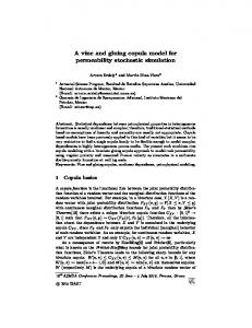
Natural fibre composites in LCM processes NFRPs accounted for over 13% of the 2.4 million tonne EU FRP market in 2010 (Fig.
1) (Carus 6-7 July 2011; Carus 2008; Shah 2013; Shah 2013). While wood and cotton were used as reinforcements in the majority of these NFRPs (most likely due to their wide availability and low cost (Shah 2013)), even the production of non-wood, non-cotton, plant fibre (e.g. flax, jute, hemp) reinforced plastics (PFRPs) was comparable to the production of non-glass, synthetic fibre (e.g. carbon, aramid) composites.
85.0%
13.1%
NFRPs
2.0% 7.1% 4.2% 1.9%
0%
Glass fibre reinforced plastics (GFRPs) Carbon, aramid and other composites Wood plastic composites Cotton fibre composites Plant fibre composites (PFRPs)
20% 40% 60% 80% 100% PFRPs: Thermosets - compression moulded PFRPs: Thermoplastics - compression moulded PFRPs: Thermoplastics - injection/extrusion moulded
Fig. 1. The production of NFRPs in the 2.4 million tonne EU FRP market in 2010 (Carus 6-7 July 2011; Carus 2008; Shah 2013; Shah 2013).
The increasing consideration of natural fibres as next-generation, sustainable reinforcements requires tackling the first hurdle, which is composite manufacture (reviewed in (Pickering 2008; Summerscales 2010; Faruk 2012; Ho 2012; Shah 2013)). Due to the commercial applications of NFRPs in predominantly small-sized, high-volume, lowcycletime, non-structural components (e.g. decking for construction industry, and interior panels for automotive industry), injection/extrusion moulding and compression moulding are the widely used manufacturing techniques (Fig. 1) (Shah 2013; Carus 2014). The reinforcement form has typically been pellets/granules for the former and random fibre mats for the latter. While wood and cotton reinforced NFRPs largely (>80%) employ
Page 3 of 43
thermosetting matrices, PFRPs are primarily (>70%) based on thermoplastic matrices (Fig. 1) (Carus 2008; Shah 2013; Carus 2014). LCM, on the other hand, is particularly suitable for (semi-)structural components utilising textile reinforcements (comprising of aligned, continuous yarns/tows that are knitted/woven/stitched/braided) in thermosetting matrices at high fibre fractions. Other than the potential to produce high-performance composites, LCM processes are specifically wellsuited to natural fibre reinforcements for a variety of reasons (Francucci 2012; Shah 2013; Shah 2013): i) low processing temperatures (often 0.99.
v f a1 P b1 , where P is in [ Pa]
Eq. 4
where, a1 is the fibre volume fraction at 1 Pa and b1 is the stiffening index. a1 and b1 typically range between 0.02-0.12 and 0.1-0.2 for unidirectional plant fibre reinforcements, and between 0.002-0.010 and 0.25-0.35 for random-mat plant fibre reinforcements (Madsen 2004).
v f v0 a 2 P b2 , where P is in [bar ]
Eq. 5
where, v0 is the initial fibre volume fraction at no compaction pressure, and a2 and b2 are the ‘additional’ fibre volume fraction (i.e. vf – v0) at 1 bar, and the reinforcement stiffening index, respectively. v0, a2 and b2 typically range between 0.3-0.4, 15-20 and 0.3-0.5 for woven silk textiles, and between 0.2-0.3, 5-10 and 0.35-0.45 for woven plant fibre textiles (Shah 2014). To compare materials that have been characterised with different models (e.g. Eq. 4 and Eq. 5), often the uncompacted fibre volume fraction (indicated by a1 in Eq. 4 and v0 in Eq. 5) and the fibre volume fraction at a reference compaction pressure are used. Page 9 of 43
2.1.2
Key compaction mechanisms While empirical models are useful for inputs in process simulations, analytical studies
provide an understanding of the mechanisms driving compaction (Chen 1999; Chen 2000; Chen 2001). Table 2 identifies the main factors contributing to the compaction of randommat, non-woven, and woven preforms. The primary and secondary mechanisms have been indicated.
Page 10 of 43
Table 2. The dominant and secondary compaction mechanisms at the fibre, yarn and fabric scales in random-mat, non-woven, and woven preforms. Scale Fibre/filament
Mechanism
Dominant in
Secondary in
all plant fibre preforms
-
all
-
random-mat
woven and nonwoven
yarn flattening
woven
random-mat
fibre/yarn bending deformation
-
all
nesting and packing
woven
non-woven
cell wall/lumen collapse (fibre cross-section deformation)
fibre lumen
yarn cross-section deformation Yarn/tow yarn
void condensation (i.e. closing gaps between fibres)
fibre
Fabric/preform
Page 11 of 43
As shown in Fig. 3, natural fibre preforms experience all the compaction mechanisms that synthetic fibre preforms experience (described in Table 2), but not vice-versa.
Fig. 3. Compaction mechanisms in various natural fibre preforms: a) yarn cross-section deformation, void consolidation, and nesting/packing in a non-woven unidirectional flax composite (Shah 6-7 July 2011; Shah 2013; Shah 2014). b) fibre bending and flattening, and void consolidation in a randommat wood fibre composite (Lundquist 2004). Yarn cross-section deformation and flattening, and nesting/packing in a woven flax composite (Goutianos 2007).
In particular, cross-section deformation at the fibre scale (Table 2) is limited to plant fibre reinforcements, which due to their hollow nature and low transverse stiffness and strength (Shah 2012; Shah 2013), undergo lumen closure and transverse cell-wall buckling and delamination during compaction (Lundquist 2004; Francucci 2012; Francucci 2013). This is illustrated in Fig. 4. A substantial change in fibre cross-section shape is not unimportant in the context of preform compaction, as it may alter the potential for fibre relative motion and yarn reorganisation, and could possibly lead to hindered impregnation in localised inter-fibre zones. Lundquist et al. (Lundquist 2004) found that lumen compression occurred between fibre volume fractions of 34% to 69% in wood pulp random-mat preforms (Fig. 4). Void condensation is a dominant compaction mechanism, particularly at low compaction pressures (e.g. when vf 55%). Francucci et al. (Francucci 2012) have also observed such irreversible transverse cell-wall deformation in compacted woven jute fabrics, and this phenomenon increased as the fibre content increased. They noted that this mechanism would contribute, alongside irreversible yarn cross-section deformation, yarn flattening, and yarn nesting, to the Page 12 of 43
compaction of the woven material. However, Francucci et al. opined that such lumen collapse would mostly occur when fibre rearrangement and tow movements are limited i.e. at high fibre volume fractions. This is in stark contrast with the observation of Lundquist et al. (Lundquist 2004) described previously, where all wood pulp lumen had collapsed by vf = 69%, and the wood pulp random-mat was compressed further up to vf = 90%.
Fig. 4. Left: Increased compaction pressure on a wood pulp random-mat increases the fibre volume fraction, with partial contribution from cumulative lumen collapse-associated fibre deformation (Lundquist 2004). Inset SEM depicts a collapsed fibre. Right: Lumen collapse observed in a woven jute fabric due to increase in compaction pressure at higher fibre volume fractions (Francucci 2012).
It is worth mentioning, however, that the luminal porosity in plant fibres varies between different species, and even evolves with age within the same fibre. For instance, luminal porosities range between 74-80% in kapok fibres, 20-70% in wood fibres, and 2-11% in flax fibres (Shah 2013). The luminal porosity has a significant effect on the transverse stiffness and yield strength in both compression and tension (Gassan 2001; Lundquist 2004; Placet 2012), where fibres with a larger lumen (and smaller second moment of area) would tend to deform more readily. Naturally, therefore, different plant fibres would exhibit different degrees of fibre bending and cross-section deformation during plant fibre preform compaction. Moreover, not all natural fibres have a central lumen; proteinaceous animal fibres like silk and wool are solid. Nonetheless, natural fibres tend to have low transverse properties due to their hierarchical, anisotropic structure (Ho 2012; Shah 2012; Shah 2014). For instance, silks have a low transverse compressive modulus of 0.5-0.7 GPa (Ko 2001) and a high Poisson’s ratio of 0.4-0.5 (Zhang 2010). Consequently, they undergo no change in crosssectional area, but experience substantial deformation (i.e. flattening in cross-section shape) with increasing compressive force (Ko 2001). While a 20% reduction in thickness has been Page 13 of 43
recorded for spider silk for compressive stresses of about 20 MPa (200 bar) (Ko 2001), compaction pressures during LCM rarely exceed 1.5 MPa, below which the expected change in cross-section is negligible. Other micro- and macro-structural features, such as fibre cross-section shape and surface roughness (relating to fibre slippage), and degree of fibre alignment and dispersion, affect which (and when) compaction mechanisms will play primary and secondary roles. 2.2
Through-thickness compaction of natural fibre preforms The compaction response of reinforcement preforms is complex and depends on
various elements, such as: type and form of fibre reinforcement, fibre architecture, number of layers in the preform, preform stacking sequence, history of loading, rate of compaction, tooling temperature, and presence of lubricant (i.e. wet versus dry state) (Kim 1991; Robitaille 1998; Kelly 2004; Correia 2005; Long 2005; Francucci 2012). 2.2.1
Effect of fibre type on single-cycle dry compaction The compaction behaviour of various reinforcement preforms is presented in Fig. 5.
The data is a compilation from (Madsen 2004; Francucci 2013; Shah 2014), where various natural fibre reinforcements have been characterised. Note that the preform architecture has a substantial effect on the compaction response of a material. In this section, we discuss the sole effect of fibre type. It is consistently observed that plant fibre reinforcements are considerably less compactable than synthetic fibre reinforcements, but natural silkworm silk fibres are as compactable as, if not more compactable than, glass fibres. It is notable that both the initial uncompacted fibre volume fraction (a1 in Eq. 4 and v0 in Eq. 5) and the fibre volume fraction at a reference compaction pressure (e.g. 2 MPa or 2 bar) follow this trend (Fig. 5). This suggests that the compaction pressure needed to achieve any fibre volume fraction (within the range studied) is significantly lower in the case of silk and glass reinforcements than for plant fibre reinforcements. Moreover, amongst plant fibres, flax is found to be more compressible than hemp, which in turn is more compressible than jute. Besides the differences in vertical positions (reflected by differences in fibre volume fractions at zero and reference compaction pressures), the shape of the compaction curves is also different for different fibre reinforcements. One could compare fitting parameters of Eq. 4 (namely b1) and 5 (namely, a2 and b2) to evaluate the differences in fibre type. For instance, Page 14 of 43
glass and silk fibre reinforcements exhibit a steeper increase in fibre volume fraction at low compaction pressures than plant fibre reinforcements; this is indicated by small b1 values in Eq. 4 (Madsen 2004) and large a2 values in Eq. 5 (Shah 2014) (Fig. 5). For reference, fitted model parameters are presented in Fig. 5.
Fig. 5. Compaction curves for various reinforcement preforms comparing the effect of fibre type and architecture. Plant fibre preforms are consistently less compactable than glass fibre preforms; natural silk preforms, however, are significantly more compressible than plant fibre preforms (and even more than glass fibre preforms – see text). Generally, non-woven (NW) preforms tend to be more compactable than woven (W) preforms, which in turn are more compactable than random-mat (R) preforms. PW refers to plain-woven, while UD refers to unidirectional fabrics. The graphs are adapted from a) (Madsen 2004) , b) (Francucci 2013), and c) (Shah 2014). For reference, fitted model parameters are provided in the table.
Analysing micro- to macro-structural features (i.e. fibre to yarn to fabric) in the silk, plant fibre and glass fibre reinforcements may explain these observations. At the fibre-scale, i) degree of fibre separation, ii) fibre surface roughness, iii) fibre cross-section shape, and iv) fibre mechanical properties are notable factors. Firstly, preforms with well-separated fibres compact more readily due to increased degrees of freedom Page 15 of 43
(Madsen 2004). While plant fibres typically exist as bundles, silk fibres, like synthetic glass fibres, are well-separated from one another (Fig. 6 a and b). Notably, it is the residue of the natural binding agent that dictates whether the fibres are separated or bundled. Pectin, the binding agent between elementary plant fibres to form a technical plant fibre bundle, is usually only partially decomposed during the fibre extraction process. On the other hand, the fibroin strand in silkworm silk is usually well-degummed from the sericin binder. Secondly, the friction between fibre to fibre contacts is a relevant factor (Long 2005), as fibre, yarns and fabric layers move (i.e. slide against each other) to dissipate energy during compaction. Plant fibres have a rougher surface than both silk and glass fibres (Fig. 6 c and d), and consequently the latter may find it easier to adjust to a more efficient packing arrangement due to lower friction forces (Francucci 2013; Shah 2014). Thirdly, the irregular almost-triangular crosssection shape of single silk fibres also permits higher ‘intra-yarn’ packing densities than irregular polygonal cross-section plant fibres (Fig. 6 e and f) (Shah 2014). Finally, as the longitudinal and transverse elastic tensile modulii of silk and flax are 7-17 GPa and 0.5-0.7 GPa, and 50-70 GPa and 4-9 GPa (Shah 2012), respectively, and as the ultimate failure strain of silk and flax is 15-30% and 2-4% (Shah 2012), respectively, silks can undergo much greater bending deformation without fibre breakage to enable efficient nesting and inter-layer packing. In fact, fibre breakage and lumen collapse have been reported to be two critical mechanisms responsible for the permanent deformation of plant fibre preforms during compaction (Francucci 2012). Glass fibres, on the other hand, are stiff, isotropic fibres. It would be expected that fibre bending would be a more compaction mechanism in silk and plant fibre reinforcements than glass fibre reinforcements.
Page 16 of 43
Fig. 6. Micrographs depicting: a) the bundled nature of plant fibres, and b) the fibrillated nature of silk fibres; c) plant fibres have a rougher surface than d) silk fibres; e) silk fibres have irregular almost-triangular cross-section shape, while f) plant fibres have irregular polygonal cross-section shape. From (Shah 2014).
At the yarn and fabric scale, i) yarn/fabric geometry, and ii) fibre alignment are notable factors. Regarding fabric geometry, the tightness of a weave and inter-yarn porosity, for instance, will affect preform compactibility. Silk textiles, like glass fibre textiles, are more tightly woven than plant fibre textiles (Fig. 7), thereby imparting high packing density, particularly at low compaction forces. This would explain the high values of v0 and a for silk textiles in comparison to plant fibre textiles (Shah 2014). Regarding yarn geometry, while plant fibre yarns tend to have a circular cross-section due to high twist factors, silk fibre assemblies, much like glass fibre assemblies, have large width-to-thickness ratios (of ~5). The lenticular cross-section shape of silk rovings would enable higher ‘inter-yarn’ compaction than twisted plant fibre yarns (Shah 2014). Moreover, this also reduces crimp. High crimp in woven fabrics would lead to higher ‘hills’ and lower ‘valleys’. It would be expected, therefore, that yarn bending deformation and nesting would be more important compaction mechanisms in plant fibre textiles than silk textiles. Crimp is one source of fibre misorientation that has a detrimental effect on compaction. In terms of orientation, the arrangement of yarns in the fabrics is clearly more ordered and uniform in the silk textiles (Fig. 7). Studies on the compaction of both E-glass and plant fibre reinforcements have reported that rovings are significantly more compactable than twisted yarns (Kim 1991; Madsen 2004). This is because yarn twist induces fibre Page 17 of 43
misorientation and transverse pressure, both of which are detrimental to effective packing (Shah 2013). Note that twist is a 3D phenomenon and that yarn twist (and yarn packing fraction) are a function of yarn radius; the twist angle and packing fraction are highest and lowest, respectively, at the yarn surface (Shah 2013). As observed in Fig. 7, while the plant fibre textiles employ yarns that are twisted (surface twist angle of 20 to 30°), the silk textiles employ rovings of well-aligned filaments. Studies have shown that not only yarn twist, but yarn hairiness (or fluffiness) is also an important source of misorientation (Kim 1991). Elementary plant fibres have non-uniform width in the range of 10-100 μm and a short length in the range of 4-100 mm (Lewin 2007). Due to the short length of staple plant fibres, during the spinning process not all fibre ends are integrated into the yarn structure. The distribution (length and frequency) of fibre ends protruding from the fibre surface is referred to as yarn ‘hairiness’ by textile engineers. These protruding fibres have a negative impact on the packing of a fabric preform. Kim et al. (Kim 1991) report that the compaction response of a fluffy roving may be as poor as that of a twisted spun yarn, relative to a straight roving; for instance, straight roving preforms have fibre volume fractions of 70% at compaction pressures of 2 MPa, compared to fibre volume fractions of only 50% for both fluffy roving and spun yarn preforms. As observed in Fig. 7, numerous fibres are protruding from the structure of the yarns in the flax textiles, while filaments in the silk fibre textiles are well-integrated into the roving. It is noteworthy that the sources of misorientation (yarn twist and yarn hairiness) are lacking in silk textiles because silks exist as long fibres (i.e. filaments), unlike staple plant fibres. In fact, silks, such as those industrially
processed
from
the
silkworm
cocoons,
exist
as
single
continuous
filaments/strands of fibroin with lengths of up to 1500 m (Lewin 2007). Put it simply, it is easier to align longer fibres than shorter fibres.
Page 18 of 43
Fig. 7. Micrographs depicting woven textiles of flax and hemp (a and b) and silk (c and d). From (Shah 2014).
2.2.2 Effect of fabric architecture As shown in Table 2, the fabric architecture plays a key role in determining the mechanisms that drive compaction. The effect of fabric architecture on the compaction of synthetic fibres has been studied in some detail (Kim 1991; Robitaille 1998; Yang 2012) and similar trends have been reported in the limited articles investigating natural fibre reinforcements (Madsen 2004; Francucci 2013; Shah 2014). As observed in Fig. 5, unidirectional non-wovens tend to be more compactable than woven fabrics, which in turn are more compactable than random-mat reinforcements. Notably, the compaction curves shift upwards (i.e. higher fibre fractions at zero (a1 in Eq. 4 and v0 in Eq. 5) and reference compaction pressures), exhibit a steeper rise at low compaction pressures (i.e. smaller b1 in Eq. 4 and larger a2 in Eq. 5), and become more flat at high compaction pressures. Fibre alignment/orientation is a mechanism-governing factor in fabric architecture. For instance, in unidirectional fabrics, fibres in adjacent layers are parallel to each other and can therefore fill gaps by dislodging other fibres to produce a compact structure. In woven fabrics, however, fibres/yarns leave voids during cross-over (weave density) that cannot be Page 19 of 43
filled by cross-over fibres in other layers. Essentially, fibre packing between layers with the same fibre/yarn orientation is easier than packing between layers with different fibre/yarn orientation. Of course, in aligned reinforcements (non-woven and woven), the stacking sequence also affects the compaction response, but this has not been studied on natural fibre reinforcements so far. Alongside fibre orientation, fibre/yarn length and diameter may also affect preform compaction. Umer et al. (Umer 2011) and Madsen et al. (Madsen 2004) investigated the compaction behaviour of random-mats constructed with yarns of varying length and diameter. Madsen et al. (Madsen 2004) found that compaction curves of hemp yarn randommats, with mean yarn lengths of 2, 10 and 50 mm, were nearly identical. In contrast, Umer et al. (Umer 2011) observed that the required compaction pressure for 50 mm flax yarn randommat was about 40% higher in comparison to a 15 mm flax yarn random-mat. They attributed the poorer compactibility of longer yarn mats to the larger number of bundle-bundle crossover points. Umer et al. (Umer 2011) also found that flax random-mats were significantly more compactable when larger diameter yarns were employed. They suggested that there were more fibres in larger diameter yarns that were more efficiently packed within the available space (than they would be as loose fibres in the mat), and consequently there were less fibre cross-over points within the mat. 2.2.3
Effect of multiple compaction cycles Multiple compaction cycles have a noticeable and well-documented effect on preform
compaction (Kim 1991; Robitaille 1998; Long 2005). Natural fibre reinforcements, like synthetic fibre reinforcements, follow the general trend (Madsen 2004; Francucci 2012; Shah 2014): i) in comparison to the first cycle, the second compaction cycle requires a relatively lower compaction pressure to achieve a given fibre volume fraction; ii) subsequent compaction cycles (i.e. third, fourth and fifth) overlay with the second compaction cycle, and iii) all compaction curves share the same asymptotic fibre volume fraction (at very high compaction pressures) (Fig. 5). With regards to the fitting model parameters, in comparison to the first compaction cycle, the uncompressed fibre volume fraction (a1 in Eq. 4 and v0 in Eq. 5) tends to increase and a steeper rise at low compaction pressures is observed (i.e. smaller b1 in Eq. 4 and larger a2 in Eq. 5) for the second compaction cycle. Subsequent compaction cycles have fairly identical fitting parameters to the second cycle.
Page 20 of 43
Maximising the fibre content is appealing for NFRPs, not only to improve composite mechanical performance (Shah 2012; Shah 2013), but also to increase the content of biobased material and reduce the amount of polymer. The latter improves sustainability credentials as natural fibres require significantly less energy for production than both synthetic fibres and polymer matrices (Duflou 2012; Shah 2013). The afore-mentioned findings provide useful insights in developing high fibre content NFRPs. If high compaction pressures, such as those realised using an autoclave for LCM (up to 15 bar) or a mechanical press for compression moulding (up to 100 bar), are used, a single compaction cycle is sufficient. That is, pre-compaction is not necessary. However, if low compaction processes are employed, such as in vacuum-bagging, pre-compaction of the reinforcement is an attractive technique to improve preform compaction and increase the part fibre volume fraction. Notably, multiple compaction cycles generally lead to the reorganisation and permanent deformation of fibres/yarns within the textiles, driven through both elastic and irreversible mechanisms, such as those illustrated in Table 2. Compaction mechanisms such as fibre/yarn cross-section deformation, yarn flattening and nesting tend to become more significant at higher compaction pressures (and thus fibre volume fractions) (Francucci 2012); therefore, the maximum compaction pressure of the previous cycle has an effect on the compaction in the next cycle. In addition, stacked textiles have a time-dependent viscoelastic behaviour (Francucci 2012), therefore studying preform relaxation is as important as studying preform compaction. In fact, relaxation studies post-multiple compaction cycles have revealed that plant fibre reinforcements undergo significantly more irreversible, permanent deformation than glass fibre reinforcements (Francucci 2013). 2.2.4
Wet compaction In LCM, while the preform is first compacted in the dry state (in the mould-filling
stage), once the preform has been impregnated, the saturated preform undergoes ‘wet compaction’ (in the post-filling stage) (Table 1). During and post impregnation, the compaction pressure exerted on the partially- or fully-saturated preform is only partially felt by the reinforcement; the remaining compaction pressure is managed by the liquid resin (Long 2005). However, lubricating effects of the liquid tend to reduce the compaction pressure required to achieve a given fibre volume fraction. This is because lubrication of fibre-to-fibre contact points mean that individual fibres find it easier to move and slide, and realign and reorganize. As a corollary, it is also expected that as the fibres are likely to attain Page 21 of 43
a higher degree of stability for a given compaction pressure, the preform would exhibit less relaxation (when held at a constant thickness). These assertions have been found to be true for synthetic fibre preforms (Kim 1991; Long 2005). Natural fibres, including plant and animal fibres, are different from synthetic fibres like glass, in that natural fibres tend to be polar and hydrophilic. That is, natural fibres absorb polar liquids; this not only includes liquids used during compaction and permeability testing like water and glycerine solution, but also includes polar thermosetting resins such as vinylester and phenolics (Francucci 2010). Moreover, natural fibres swell upon liquid absorption (10-25% moisture regain) (Francucci 2010). For instance, over an immersion time of 6000 seconds, jute fibres exhibited equilibrium transverse swelling (i.e. change in diameter) by over 18% in glycerine solution, and between 6 to 8% in vinylester and phenolic resin (Fig. 8a). In comparison, glass fibres do not absorb liquid ( Kunsat), ii) capillary and wicking effects (leading to Kunsat > Ksat), and iii) transverse micro-flow into tows, which occurs after macro-flow between tows, increases penetration/impregnation times (leading to Ksat > Kunsat) (Dungan 2002). It has been observed for natural fibre reinforcements that saturated permeability is higher than the unsaturated permeability. Ksat/Kunsat ranges between 1.2-1.8 for plain-woven jute fabrics (Dungan 2002). Like Pillai and Advani (Pillai 1998), Francucci et al. (Dungan 2002) argue that the jute yarns act as a ‘sink’, leading to a delayed impregnation of the tows through transverse micro-flow, which reduces the average macro-flow velocity, thereby reducing permeability. An alternate explanation provided for the high saturated permeability related to the absorption of fluid by the natural reinforcements (Dungan 2002). Again, as the jute fibres and yarns act as sink components (as fibres absorb liquid, and yarns have micro-pores), the unsaturated permeability is reduced. Once infusion is complete (i.e. no more porosity within tows need to be filled and fibres cannot absorb more fluid), the fibres and yarns are no longer sink components, and the permeability upon saturation is increased. Note that the swelling of the fibres upon saturation does restrict flow paths and therefore the increase is only marginal. This argument is further strengthened by the fact that the difference between saturated and unsaturated permeability vanishes with increasing porosity (decreasing fibre volume fraction) (Fig. 11). In fact, at very high porosity (ϕ > 0.8), Ksat/Kunsat < 1 (Fig. 11). Notably, the difference between saturated and unsaturated permeability is higher in untreated jute fabrics (Ksat/Kunsat = 1.70-1.84) than in treated jute fabrics (Ksat/Kunsat = 1.211.40) (Dungan 2002). This suggests that while transverse micro-flow into tows may play an important role in the difference in saturated and unsaturated permeability of natural fibre reinforcements, the polar nature of untreated natural fibres and their tendency to absorb polar fluids and swell has a more dominant role.
Page 33 of 43
3.1.5
Capillary effects and micro-flow versus macro-flow Preform impregnation usually involves a dual-scale flow. Resin flow between yarns
(inter-yarn) is referred to as macro-flow, while resin flow through the yarns (intra-yarn) is referred to as micro-flow. As resin flows at low Reynolds numbers, inertial forces can be neglected. Macro-flow is dominated by viscous flow of the resin, while micro-flow is driven by capillary pressure developed within the tows. Capillary effects are important to study, not least because they play a key role in the mechanism of void formation in LCM. As Fig. 9 highlights, at low flow velocities (and high fibre volume fractions) capillary flow dominates leading to inter-yarn voids, while at high flow velocities (and low fibre volume fractions) viscous flow dominates leading to intra-yarn voids. This has been shown for plant fibre composites as well (Fig. 9) (Shah 2012; Shah 2013). Capillary effects in natural fibre reinforcements have received some attention (Francucci 2012; Sun 2014), particularly due to the common (but incorrect) notion that the hollow structure of plant fibres may enhance capillary effects. There is little evidence that resin can impregnate the lumen, and in most cases the lumen has shown to remain unfilled after composite manufacture (Madsen 2004; Shah 2013). Investigations have revealed that the dynamic capillary pressure in plain-woven jute fabrics was -25 kPa and 36 kPa when measured in the glycerine solution and vinylester resin, respectively (Francucci 2012). That is, spontaneous infiltration occurs during infusion with glycerine solution, but capillary forces act against flow during infusion with the resin. This has significant implications on experimental mould-filling tests as test fluids like glycerine solution may provide deceivingly higher permeability and lower fill times. The capillary pressure is found to increase exponentially with fibre volume fraction (Francucci 2012). Notably, the jute fabrics consistently exhibited capillary pressures two to three times higher than synthetic reinforcements (Francucci 2012), implying that capillary effects and micro-flow are more dominant in natural fibre reinforcements. Francucci et al. (Francucci 2012) also demonstrate that the measured capillary pressure may be used to determine a corrected unsaturated permeability, which is found to be similar for both the test fluid and resin.
Page 34 of 43
3.2 3.2.1
Flow modelling of natural fibre composites Introduction Darcy’s law (Eq. 11) and the continuity equation (Eq. 12) are commonly and
conveniently used to describe the flow of thermosetting resins in porous reinforcements. v
K
P
v 0
Eq. 11 Eq. 12
, where v is the volume-averaged fluid velocity, and P is the applied pressure gradient. All permeability studies on natural fibre reinforcements so far have been conducted on the presumption of a valid 1D Darcy’s law. The mould-filling of natural fibre reinforcements has been successfully simulated and experimentally validated using the conventional model by some researchers, including Kong et al. (Kong 2014). They performed a resin flow analysis on the upper and lower parts of a flax/vinylester agricultural chemical storage tank, to predict fill times (and select a suitable injection pressure) and ensure complete impregnation. A flow simulation of the lower part is illustrated in Fig. 14. The simulations were backed by experiments.
Page 35 of 43
Fig. 14. Resin flow simulation conducted in RTM-Worx software for the vacuum-assisted, light-RTM manufacture of the lower part of a flax/vinylester composite agricultural chemical storage tank. Adapted from (Kong 2014).
3.2.2 Models suitable for natural fibre reinforcements During resin impregnation in an LCM process, natural fibre reinforcements, unlike synthetic reinforcements, absorb liquid and subsequently swell. As discussed previously, the percentage absorption and swelling is dependent on the (polarity of the) liquid; for instance, jute swells by 18-22% in glycerine solution but by 7-8% in vinylester or polyester resin (Francucci 2010). Due to the absorption of liquid, natural fibre preforms effectively act as a ‘sink’, soaking up some volume of the resin that is infused. The subsequent fibre volume Page 36 of 43
change due to swelling has a two-fold, time-dependent, ‘source-like’ effect: i) reducing porosity and thus permeability, and ii) increasing flow resistance. The conventional model in Eq. 11 and 12 is therefore inappropriate, if not ineffective, in describing the permeability of, and resin flow behaviour in, natural fibre reinforcements as it does not take these sink and source factors into account. Several researchers have recently attempted to develop flow models specifically for natural fibre reinforcements, including (Languri 11-15 July 2010 ; Nguyen 14-16 July 2014; Masoodi 15-17 September 2009; Masoodi 2010; Masoodi 2011; Francucci 2014). A modified continuity equation (Eq. 13) was initially proposed, which incorporated a sink term S(t) that was related to the rate of fluid absorption by the reinforcement, and a porosity term ϕ’(t) that was related to the rate of decrease in preform porosity due to increase in fibre volume upon swelling, both of which were functions of time (Languri 11-15 July 2010 ; Masoodi 15-17 September 2009; Masoodi 2010; Masoodi 2011). However, it was later found that sink and porosity terms had to cancel out to satisfy experimental observations (Masoodi 2010; Masoodi 2011); that is, the rate of fluid absorption (per unit volume) had to be equal to the rate of change of fibre volume (per unit volume). Consequently, Eq. 13 simplified to the conventional continuity equation of Eq. 12. v S (t ) ' (t )
Eq. 13
Following this, Masoodi et al. (Masoodi 2011) proposed that the permeability K, alongside porosity ϕ and fibre diameter d, were only functions of time (Eq. 14), where the subscript 0 indicates initial values (at t = 0). Essentially, if the change in fibre diameter over time (due to swelling) was measured, fitted curves could be used to then predict evolution of porosity with time, and the evolution of permeability with time. Then, if evolution of the pressure gradient as a function of time was known, Eq. 15, which is derived by resolving Darcy’s law (Eq. 11) with the continuity equation (Eq. 13), could be used to predict the evolution of the flow-front. K (t )
(t ) n 1 C (1 (t )) n
, where (t ) 1 (1 0 )
2
x (t )
2
d (t ) b , and d (t ) a exp Eq. 14 d0 ct
t
0
P(t )K (t )dt
0
Page 37 of 43
Eq. 15
The above model has been used with much success by Masoodi et al. (Masoodi 15-17 September 2009; Masoodi 2011) and Languri et al. (Languri 11-15 July 2010 ) in predicting the flow in natural fibre reinforcements. This particularly demonstrates the important of tracking the evolution of permeability as a function of time in natural fibre reinforcements. 3.3
Conclusions Permeability studies and data are imperative to understanding and modelling the
mould-filling stage in LCM of composites. Plant fibre reinforcements demonstrate higher permeability than glass fibre reinforcements, while wood fibre reinforcements exhibit lower permeability than the latter. Permeability of natural fibre reinforcements increases with porosity, and can be modelled by conventional models such as the modified Carman-Kozeny equation. Yarn diameter (linear density), length and twist level are all found to affect preform permeability. Fluid absorption and swelling are key mechanisms in natural fibre preforms, due to which both saturated and unsaturated permeability are reduced. For natural preforms, saturated permeability tends to be higher than unsaturated permeability, although the difference vanishes with increasing porosity (decreasing fibre volume fraction). Moreover, capillary effects and micro-flow are more dominant in natural fibre reinforcements than in conventional synthetic reinforcements. Importantly, as natural fibres behave differently with different liquids (viz. absorption, swelling, and capillary pressure), to accurately measure their permeability, the natural fibre reinforcement should be studied with the particular resin that is to be used during LCM as the test fluid. To accurately model the mould-filling stage in LCM of natural fibre reinforcements, researchers have proposed experimentally-validated Darcy’s law-based models, which specifically incorporate effects of liquid absorption and subsequent fibre swelling on preform porosity and permeability as a function of time. References (18/06/2012). "Samsara 'eco surfboard' features Biotex flax fibre." Retrieved 11/08/2014, from http://www.reinforcedplastics.com/view/26369/samsara-eco-surfboard-features-biotex-flax-fibre/. Cai, Z. (1992). "Analysis of mold filling in RTM process." Journal of Composite Materials 26: 1310-1338. Campbell, F. (2003). Manufacturing processes for advanced composites. Oxford, UK, Elsevier. Carman, P. (1937). Fluid flow through granular beds. Transactions. London, Institution of Chemical Engineers. 15: 150-166. Carus, M. (6-7 July 2011). Bio-composites: Technologies, applications and markets. 4th International Conference on Sustainable Materials, Polymers and Composites, Birmingham, UK. Carus, M., Eder A, Dammer L, Korte H, Scholz L, Essel R, Breitmayer E (2014). Wood-plastic composites (WPC) and natural fibre composites (NFC): European and global Markets 2012 and future trends. WPC/NFC Market Study 2014-03. Hürth, Germany, nova-Institut GmbH. Carus, M., Gahle C (2008). Natural fibre reinforced plastics - material with future. Huerth, nova-Institut GmbH.
Page 38 of 43
Chen, B., Chou TW (1999). "Compaction of woven-fabric preforms in liquid composite molding processes: single-layer deformation." Composites Science and Technology 59: 1519-1526. Chen, B., Chou TW (2000). "Compaction of woven-fabric preforms: nesting and multi-layer deformation." Composites Science and Technology 60: 2223-2231. Chen, B., Lang EJ, Chou TW (2001). "Experimental and theoretical studies of fabric compaction behavior in resin transfer molding." Materials Science and Engineering: A 317(1-2): 188-196. Correia, N., Robitaille F, Long AC, Rudd CD, Simacek P, Advani SG (2005). "Analysis of the vacuum infusion moulding process: I. Analytical formulation." Composites Part A: Applied Science and Manufacturing 36: 1645-1656. Duflou, J., Deng Y, Acker KV, Dewulf W (2012). "Do fiber-reinforced polymer composites provide environmentally benign alternatives? A life-cycle-assessment-based study." MRS Bulletin 37: 374-382. Dungan, F., Sastry AM (2002). "Saturated and unsaturated polymer flows: Microphenomena and modeling." Journal of Composite Materials 36(13): 1581-1603. Faruk, O., Bledzki AK, Fink HP, Sain M (2012). "Biocomposites reinforced with natural fibres: 2000-2010." Progress in Polymer Science 37(11): 1552-1596. Francucci, G., Rodrıguez ES, Moran J (2014). "Novel approach for mold filling simulation of the processing of natural fiber reinforced composites by resin transfer molding." Journal of Composite Materials 48(2): 191-200. Francucci, G., Rodrıguez ES, Vazquez A (2010). "Study of saturated and unsaturated permeability in natural fiber fabrics." Composites Part A: Applied Science and Manufacturing 41: 16-21. Francucci, G., Rodrıguez ES, Vazquez A (2012). "Experimental study of the compaction response of jute fabrics in liquid composite molding processes." Journal of Composite Materials 46(2): 155-167. Francucci, G., Vazquez A, Rodrıguez ES (2013). "Key differences on the compaction response of natural and glass fiber preforms in liquid composite molding." Textile Research Journal 82(17): 1774-1785. Francucci, G., Vazquez A, Rodrıguez ES (2013). "Key differences on the compaction response of natural and glass fiber preforms in liquid composite molding." Textile Research Journal In Press. Francucci, G., Vazquez A, Ruiz E, Rodrıguez ES (2012). "Capillary effects in vacuum-assisted resin transfer molding with natural fibers." Polymer Composites 33: 1593-1602. Gassan, J., Chate A, Bledzki AK (2001). "Calculation of elastic properties of natural fibers." Journal of Materials Science 36: 3715-3720. Gauvin, R., Kerachni A, Fisa B (1994). "Variation of mat surface density and its effect on permeability evaluation for RTM modelling." Journal of Reinforced Plastics and Composites 13: 371-383. Goutianos, S., Peijs T (2003). "The optimisation of flax fibre yarns for the development of high-performance natural fibre composites." Advanced Composites Letters 12(6): 237-241. Goutianos, S., Peijs T, Nystrom B, Skrifvars M (2007). Textile reinforcements based on aligned flax fibres for structural composites. Composites Innovation 2007 - Improved sustainability and environmental performance. Barcelona, Spain. Gutowski, T., Cai Z, Bauer S, Boucher D, Kingery J, Wineman S (1987). "Consolidation experiments for laminate composites." Journal of Composite Materials 21: 650-669. Gutowski, T., Morigaki T, Cai Z (1987). "The consolidation of laminate composites." Journal of Composite Materials 21: 172-188. Ho, M., Wang H, Lee J, Hoc C, Lau K, Leng J, Hui D (2012). "Critical factors on manufacturing processes of natural fibre composites." Composites Part B: Engineering 43(8): 3549-3562. Kelly, P., Umer R, Bickerton S (2004). Compaction of dry and wet fibrous materials during infusion processes. 36th International SAMPE Technical Conference. San Diego, CA. 36: 785-797. Kim, Y., McCarthy SP, Fanucci JP (1991). "Compressibility and relaxation of fiber reinforcements during composite processing." Polymer Composites 12(1): 13-19. Ko, F., Kawabata S, Inoue M, Niwa M, Fossey S, Song JW (2001). Engineering properties of spider silk. MRS Proceedings. Vol 702. DOI: 10.1557/PROC-702-U1.4.1. Kong, C., Park H, Lee H, Lee J (2014). "Design of natural fiber composites chemical container using resin flow simulation of VARTML process." International Journal of Materials, Mechanics and Manufacturing 2(3): 256-260. Languri, E., Moore RD, Masoodi R, Pillai KM, Sabo R (11-15 July 2010 ). An approach to model resin flow through swelling porous media made of natural fibers. 10th International Conference on Flow Processes in Composite Materials (FPCM10). Monte Verità, Ascona, Switzerland. Lewin, M. (2007). Handbook of fiber chemistry. Boca Raton, CRC Press LLC. Li, Y. (2006). "Processing of sisal fiber reinforced composites by resin transfer molding." Materials and Manufacturing Processes 21(2): 181-190. Long, A., Ed. (2005). Design and manufacture of textile composites. Cambridge, England, Woodhead Publishing Limited and CRC Press LLC.
Page 39 of 43
Long, A., Boisse P, Robitaille F (2005). Mechanical analysis of textiles. Design and manufacture of textile composites. A. Long. Cambridge, England, Woodhead Publishing Limited and CRC Press LLC. Lundquist, L., Willi F, Leterrier Y, Manson JAE (2004). "Compression behavior of pulp fiber networks." Polymer Engineering and Science 44(1): 45-55. Madsen, B. (2004). Properties of plant fibre yarn polymer composites - An experimental study. PhD, Technical University of Denmark. Manson, J., Wakeman MD, Bernet N (2000). 2.16 - Composite processing and manufacturing - An overview. Comprehensive composite materials. A. Kelly, Zweben CH. Oxford, Pergamon & Elsevier Science. Volume 2: Polymer Matrix Composites. Masoodi, R., Pillai KM (2010). "Darcy’s law-based model for wicking in paper-like swelling porous media." American Institute of Chemical Engineers Journal 56(9): 2257-2267. Masoodi, R., Pillai KM (2011). 3 - Modeling the processing of natural fiber composites made using liquid composite molding. Handbook of bioplastics and biocomposites engineering applications. S. Pilla. Hoboken, NJ, USA, John Wiley & Sons, Inc. Masoodi, R., Pillai KM, Verhagen MA (15-17 September 2009). Flow modeling in natural-fiber preforms used in liquid composite molding Joint American-Canadian International Conference on Composites. Newark, Delaware, USA. Matsudaira, M. (2006). "Fabric handle and its basic mechanical properties." Journal of Textile Engineering 52(1): 1-8. Matsudaira, M., Qin H (1995). "Features and mechanical parameters of a fabric's compressional property." The Journal of The Textile Institute 86(3): 476-486. Neuman, S. (1977). "Theoretical derivation of Darcy's law." Acta Mechanica 25: 153-170. Nguyen, V., Lagardère M, Cosson B, Park CH (14-16 July 2014). Experimental analysis of flow behavior in the flax fiber reinforcement with double scale porosity. 12th International Conference on Flow Processing in Composite Materials (FPCM 12). Enschede, The Netherlands. Parnas, R., Howard JG, Luce TL, Advani SG (1995). "Permeability characterization. Part 1: A proposed standard reference fabric for permeability." Polymer Composites 16(6): 429-445. Pickering, K., Ed. (2008). Properties and performance of natural-fibre composites. Boca Raton, CRC Press LLC. Pillai, K., Advani G (1998). "A model for unsaturated flow in woven fiber preforms during mold filling in resin transfer molding." Journal of Composite Materials 32(19): 1753-1783. Placet, V., Trivaudey F, Cisse O, Gucheret-Retel V, Boubakar ML (2012). "Diameter dependence of the apparent tensile modulus of hemp fibres: A morphological, structural or ultrastructural effect?" Composites Part A: Applied Science and Manufacturing 43(2): 275-287. Reux, F. (26-28 June 2012). Worldwide composites market: Main trends of the composites industry. 5th Innovative Composites Summit - JEC ASIA 2012, Singapore. Richardson, M., Zhang ZY (2000). "Experimental investigation and flow visualisation of the resin transfer mould filling process for non-woven hemp reinforced phenolic composites." Composites Part A: Applied Science and Manufacturing 31: 1303-1310. Robitaille, F., Gauvin R (1998). "Compaction of textile reinforcements for composites manufacturing. I: Review of experimental results." Polymer Composites 19(2): 198-216. Robitaille, F., Gauvin R (1998). "Compaction of textile reinforcements for composites manufacturing. III: Reorganization of the fiber network." Polymer Composites 20(1): 48-61. Rodriguez, E., Giacomelli F, Vazquez A (2004). "Permeability-porosity relationship in RTM for different fiberglass and natural reinforcements." Journal of Composite Materials 38: 259-268. Rodríguez, E., Stefani PM, Vazquez A (2007). "Effects of fibers’ alkali treatment on the resin transfer molding processing and mechanical properties of jute-vinylester composites." Journal of Composite Materials 41: 1729-1741. Schiefer, H. (1933). "The compressometer, an instrument for evaluating the thickness, compressibility, and compressional resilience of textiles and similar materials." Bureau of Standards Journal of Research 10(6): 705-713. Shah, D. (2013). Characterisation and optimisation of the mechanical performance of plant fibre composites for structural applications. PhD, University of Nottingham. Shah, D. (2013). "Developing plant fibre composites for structural applications by optimising composite parameters: a critical review." Journal of Materials Science 48(18): 6083-6107. Shah, D., Porter D, Vollrath F (2014). "Opportunities for silk textiles in reinforced biocomposites: Studying through-thickness compaction behaviour." Composites Part A: Applied Science and Manufacturing 62: 1-10. Shah, D., Schubel PJ, Clifford MJ (2013). "Can flax replace E-glass in structural composites? A small wind turbine blade case study." Composites Part B: Engineering 52: 172-181.
Page 40 of 43
Shah, D., Schubel PJ, Clifford MJ (2013). "Modelling the effect of yarn twist on the tensile strength of unidirectional plant fibre yarn composites." Journal of Composite Materials 47(4): 425-436. Shah, D., Schubel PJ, Clifford MJ, Licence P (6-7 July 2011). Mechanical characterization of vacuum infused thermoset matrix composites reinforced with aligned hydroxyethylcellulose sized plant bast fibre yarns. 4th International Conference on Sustainable Materials, Polymers and Composites, Birmingham, UK. Shah, D., Schubel PJ, Clifford MJ, Licence P (2012). "The tensile behavior of off-axis loaded plant fiber composites: an insight on the non-linear stress-strain response." Polymer Composites 33(9): 14941504. Shah, D., Schubel PJ, Clifford MJ, Licence P (2013). "Mechanical property characterization of aligned plant yarn reinforced thermoset matrix composites manufactured via vacuum infusion." Polymer-Plastics Technology and Engineering In Press. DOI:10.1080/03602559.2013.843710. Shah, D., Schubel PJ, Clifford MJ, Licence P (2014). "Mechanical property characterization of aligned plant yarn reinforced thermoset matrix composites manufactured via vacuum infusion." Polymer-Plastics Technology and Engineering 53: 239-253. Shah, D., Schubel PJ, Licence P, Clifford MJ (2012). "Determining the minimum, critical and maximum fibre content for twisted yarn reinforced plant fibre composites." Composites Science and Technology 72: 1909-1917. Summerscales, J., Dissanayake N, Virk AS, Hall W (2010). "A review of bast fibres and their composites. Part 2 – Composites." Composites Part A: Applied Science and Manufacturing 41(10): 1336-1344. Sun, Z., Zhao X, Ma J (2014). "Capillary effect in the impregnation of jute fiber mat reinforced polypropylene composites." Journal of Composite Materials 48: 447-453. Umer, R., Bickerton S, Fernyhough A (2007). "Characterising wood fibre mats as reinforcements for liquid composite moulding processes." Composites: Part A 38: 43-448. Umer, R., Bickerton S, Fernyhough A (2008). "Modelling the application of wood fibre reinforcements within liquid composite moulding processes." Composites: Part A 39: 624-639. Umer, R., Bickerton S, Fernyhough A (2011). "The effect of yarn length and diameter on permeability and compaction response of flax fibre mats." Composites Part A: Applied Science and Manufacturing 42: 723-732. van Wyk, C. (1946). "20 - Note on the compressibility of wool." Journal of the Textile Institute Transactions 37(12): T285-T292. Winson, C. (1932). "27 - Report on a method for measuring the resilience of wool." Journal of the Textile Institute Transactions 23(12): T386-T393. Witten, E., Jahn B (2013). Composites market report 2013: Market developments, trends, challenges and opportunities. Frankfurt, Germany, Industrievereinigung Verstärkte Kunststoffe (Federation of Reinforced Plastics) and Carbon Composites eV. Xue, D., Miao M, Hu H (2011). "Permeability anisotropy of flax nonwoven mats in vacuum-assisted resin transfer molding." Journal of the Textile Institute 102(7): 612-620. Xue, D., Miao M, Hu H (2011). "Permeability anisotropy of flax nonwoven mats in vacuum assisted resin transfer molding." Journal of the Textile Institute 102(7): 612-620. Yang, J., Xiao J, Zeng J, Jiang D, Peng C (2012). "Compaction behavior and part thickness variation in vacuum infusion molding process." Applied Composite Materials 19: 443-458. Zhang, K., Si FW, Duan HL, Wang J (2010). "Microstructures and mechanical properties of silks of silkworm and honeybee." Acta Biomaterialia 6: 2165-2171.
List of Tables Table 1. Schematic and description of a generic LCM process illustrating the four principal stages. Process variations primarily relate to the choice of mould material and the resin injection/infusion mechanism. Table 2. The dominant and secondary compaction mechanisms at the fibre, yarn and fabric scales in random-mat, non-woven, and woven preforms. Table 3. Permeability data of various natural fibre reinforcements.
Page 41 of 43
List of Figures Fig. 1. The production of NFRPs in the 2.4 million tonne EU FRP market in 2010 (Carus 6-7 July 2011; Carus 2008; Shah 2013; Shah 2013). Fig. 2. Left: Testing rig for compaction of a dry reinforcement. Right: Example compaction curves for a plain woven flax fabric. The arrows indicate the direction in which the curves shift for the successive compaction cycles. Fig. 3. Compaction mechanisms in various natural fibre preforms: a) yarn crosssection deformation, void consolidation, and nesting/packing in a non-woven unidirectional flax composite (Shah 6-7 July 2011; Shah 2013; Shah 2014). b) fibre bending and flattening, and void consolidation in a random-mat wood fibre composite (Lundquist 2004). Yarn crosssection deformation and flattening, and nesting/packing in a woven flax composite (Goutianos 2006). Fig. 4. Left: Increased compaction pressure on a wood pulp random-mat increases the fibre volume fraction, with partial contribution from cumulative lumen collapse-associated fibre deformation (Lundquist 2004). Inset SEM depicts a collapsed fibre. Right: Lumen collapse observed in a woven jute fabric due to increase in compaction pressure at higher fibre volume fractions (Francucci 2012). Fig. 5. Compaction curves for various reinforcement preforms comparing the effect of fibre type and architecture. Plant fibre preforms are consistently less compactable than glass fibre preforms; natural silk preforms, however, are significantly more compressible than plant fibre preforms (and even more than glass fibre preforms – see text). Generally, non-woven (NW) preforms tend to be more compactable than woven (W) preforms, which in turn are more compactable than random-mat (R) preforms. PW refers to plain-woven, while UD refers to unidirectional fabrics. The graphs are adapted from a) (Madsen 2004) , b) (Francucci 2013), and c) (Shah 2014). For reference, fitted model parameters are provided in the table. Fig. 6. Micrographs depicting: a) the bundled nature of plant fibres, and b) the fibrillated nature of silk fibres; c) plant fibres have a rougher surface than d) silk fibres; e) silk fibres have irregular almost-triangular cross-section shape, while f) plant fibres have irregular polygonal cross-section shape. From (Shah 2014). Fig. 7. Micrographs depicting woven textiles of flax and hemp (a and b) and silk (c and d). From (Shah 2014). Fig. 8. a) Transverse swelling (in terms of % diameter change) of jute fibres in different fluids. Adapted from (Francucci 2010). b) Effect of immersion time on the compaction of jute woven fabrics. From (Francucci 2013). Page 42 of 43
Fig. 9. The complex, dual-scale flow of resin in fibrous preforms can generate voids. Macro-scale flow relates to the advance of resin between yarns/tows (i.e. inter-yarn flow), while micro-scale flow relates to the penetration of resin into a yarn (i.e. intra-yarn flow). Note that permeability is also different at the two scales. For instance, a) at low fibre content, due to low yarn permeability but high overall permeability, the yarn is not properly impregnated and thus intra-yarn voids may form, while b) at high fibre content, although yarn and overall permeability are similar, capillary flow in the yarn dominates and therefore interyarn voids are formed. From (Shah 2012; Shah 2013). Fig. 10. Permeability measurement and flow visualisation set-ups. a)-b) 1D linear flow through line-gate injection (Parnas 1995). c)-d) 2D radial flow through central injection (Parnas 1995; Xue 2011). Fig. 11. Permeability testing of woven jute fabric (Francucci 2010). a) Plot of square of flow front position with time for different infusion conditions. B) Plot of saturated and unsaturated permeability against porosity (= 1 – fibre volume fraction). Fig. 12. Resin flow in 2-layer random-mat hemp reinforcements before (a) and after (b) problems of fibre washing and edge flow were resolved. The flow front is smoother, more uniform and quasi-1D in b). Flow front isochrones are shown, where each isochrone represents 20 s. Mould filling direction is from left to right. From (Richardson 2000). Fig. 13. Comparison of the (unsaturated) permeability of sisal, jute and E-glass reinforcements. Carman-Kozeny constants are also provided. Adapted from (Rodriguez 2004). Fig. 14. Resin flow simulation conducted in RTM-Worx software for the vacuumassisted, light-RTM manufacture of the lower part of a flax/vinylester composite agricultural chemical storage tank. Adapted from (Kong 2014).
Page 43 of 43