Computer Methods in Biomechanics and Biomedical Engineering
ISSN: 1025-5842 (Print) 1476-8259 (Online) Journal homepage: http://www.tandfonline.com/loi/gcmb20
Comparison between line and surface mesh models to represent the rotator cuff muscle geometry in musculoskeletal models Marion Hoffmann, Diane Haering & Mickaël Begon To cite this article: Marion Hoffmann, Diane Haering & Mickaël Begon (2017) Comparison between line and surface mesh models to represent the rotator cuff muscle geometry in musculoskeletal models, Computer Methods in Biomechanics and Biomedical Engineering, 20:11, 1175-1181, DOI: 10.1080/10255842.2017.1340463 To link to this article: http://dx.doi.org/10.1080/10255842.2017.1340463
View supplementary material
Published online: 19 Jun 2017.
Submit your article to this journal
Article views: 66
View related articles
View Crossmark data
Full Terms & Conditions of access and use can be found at http://www.tandfonline.com/action/journalInformation?journalCode=gcmb20 Download by: [Bibliothèques de l'Université de Montréal]
Date: 08 August 2017, At: 07:26
Computer Methods in Biomechanics and Biomedical Engineering, 2017 VOL. 20, NO. 11, 1175–1181 https://doi.org/10.1080/10255842.2017.1340463
Comparison between line and surface mesh models to represent the rotator cuff muscle geometry in musculoskeletal models Marion Hoffmanna, Diane Haeringb and Mickaël Begona,c a
Institute of Biomedical Engineering, University of Montreal, Montreal, Canada; bINRIA/IRISA/M2S MimeTIC, Rennes, France; cDepartment of Kinesiology, University of Montreal, Montreal, Canada
Downloaded by [Bibliothèques de l'Université de Montréal] at 07:26 08 August 2017
ABSTRACT
Accurate muscle geometry (muscle length and moment arm) is required to estimate muscle function when using musculoskeletal modelling. In shoulder, muscles are often modelled as a collection of independent line segments, leading to non-physiological muscles trajectory, especially for the rotator cuff muscles. To prevent this, a surface mesh model was developed and validated against 7 MRI positions in one participant. Mean moment arm errors was 11.4% for the line vs. 8.8% for the mesh model. While the model with independent lines led to some non-physiological trajectories, the mesh model gave lower misestimations of muscle lengths and moment arms.
1. Introduction Rotator cuff muscles injury and dysfunction affect 20.7% of people (Yamamoto et al. 2010). The estimation of rotator cuff forces and activations could improve diagnosis and treatment (Bolsterlee et al. 2013) because important internal loads may affect anatomical structures. As in vivo measurement of muscles forces is an invasive procedure, musculoskeletal models have been developed. In those models, a muscle is typically represented by a line of action that represents its function (Damsgaard et al. 2006). Via points or wrapping objects prevent lines of action from penetrating into bones. Rotator cuff muscles have broad attachment area, miscellaneous muscles and bones obstacle and intricate fibre arrangements that make muscle function more complex (Labriola et al. 2005). Due to the large scapulohumeral range of motion (Haering et al. 2014b), the function of rotator cuff muscles also varies between distant shoulder configurations. Therefore, modelling the muscle geometry and function whatever the joint orientation remains a challenge. The main function of each rotator cuff muscle could be defined according to its geometry and architecture (Ward et al. 2006). However, because the rotator cuff muscles display broad attachments, each muscle can intrinsically have multiple functional compartments that can be complementary or sometimes antagonistic (Langenderfer et al. 2006). Therefore, modelling each muscle by a single line of
KEYWORDS
Rotator cuff; mesh model; muscle geometry; musculoskeletal model; MRI
action is too restrictive (Garner and Pandy 2001; Quental et al. 2015). In models, up to 6 lines of action have been proposed to represent each rotator cuff muscle (Van der Helm 1994; Favre et al. 2005). However, mechanical constraint between lines of action within each muscle are not accounted for (Epstein et al. 2006) and the tendon fusion around the humeral head insertion is not represented. Moreover, independent lines of action were evidenced to lead to non-physiological muscles trajectory where muscle spread over the humeral head. Mechanically, muscle function is related to its length variation and moment arms that give the amplitude and direction of torque around the joint. On one hand, muscle length misestimation affects its ability to produce force due to the force-length-velocity relationship. On the other hand, biased moment arms could change the muscle function predicted by the model (Ackland et al. 2012). Based on those relationships, musculoskeletal model are highly sensitive to muscle geometry (Maganaris 2004). Rotator cuff line model geometry should be improved to in fine have a good estimate of muscle force (Blajer et al. 2010). To improve muscle geometry fidelity, 3D finite element models has been proposed, as it respects muscle volume and the interaction between different muscle compartments or between muscles. The 3D finite element model developed by Webb et al. (2014) was only validated for simple movements like abduction and internal/external
CONTACT ; Marion Hoffmann
[email protected] Supplemental data for this article can be accessed at [https://doi.org/10.1080/10255842.2017.1340463]A © 2017 Informa UK Limited, trading as Taylor & Francis Group
RTICLE HISTORY
Received 16 November 2016 Accepted 6 June 2017
Downloaded by [Bibliothèques de l'Université de Montréal] at 07:26 08 August 2017
1176
M. HOFFMANN ET AL.
rotation and it induced a high computational time that makes its use for static optimization impossible. A simpler solution for ensuring cohesion between lines of action stands in constraints between independent lines of action of each muscle and between tendons forming the cuff around the humeral head. Marsden (2010) already proposed this method by using an elastic mesh to discretize muscle for the deltoid. Further validation of those models in vastly varied joint configurations is necessary to better assess the robustness of the model throughout the large range of motion of the shoulder (Haering et al. 2014b). Therefore, the purpose of this study was to provide a validation of a mesh-like muscle model, throughout the large range of motion of the shoulder, based on MRI acquisition. We hypothesised that constraints between the lines of action would result in a more realistic shoulder muscle geometry while conserving reasonable computation time.
2. Methods 2.1. Imaging The left shoulder bone geometry (scapula and humerus) of a 32-year-old participant with no history of shoulder pathologies or injuries (weight: 80 kg, height: 1.72 m) was imaged in axial mode using a CT-scan (Appendix 1A cited in supplemental data). Then, using a 3T-MRI scanner (MAGNETON Skyra, Siemens Healthcare), the same shoulder was imaged in seven different configurations of the arm (Figure 1). The configurations varied in
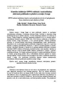
arm elevation and internal-external rotation. For each position, shoulder was imaged using a fast pin echo sequence (Appendix 1B cited in supplemental data). Three-dimensional representations of the anatomical structures in seven postures were created from the segmented images. 2.2. Development of the line and mesh models From the CT-scan based 3D reconstruction of the humerus and the scapula, two models of rotator cuff muscle were developed: a first one based on independent lines of action (termed as the line model) and a second model based on the same lines of action linked transversally (mesh model). In the line model, each rotator cuff muscle was represented by six lines of action as in previous models (Van der Helm 1994; Nikooyan et al. 2011) consisting of massless springs in series. Springs were only used to estimate muscle trajectory, not muscle force. Each line of action was composed of seven springs. The six interior nodes were distributed along the line of action using a logarithmic function to have more points close to the humeral head and reinforce bone’s wrapping. The origin and insertion points derived from the literature (Curtis et al. 2006). The mesh model (Figure 2) contains additional transverse massless traction springs between nodes. Since rotator cuff tendons interdigitate with each other to form a cuff around the humeral head, transverse springs were also added between the distal
Figure 1. Depiction of subject positioning in the MRI with the seven arm configurations and the corresponding scapulohumeral angle [plane of elevation, elevation, rotation] with respect to the anatomical position.
COMPUTER METHODS IN BIOMECHANICS AND BIOMEDICAL ENGINEERING
1177
2.3. Computation of MRI lines of action For comparison purpose, six lines of action were computed from the MRI reconstruction of each muscle (termed as MRI model). They were drawn passing through the centroid plane of the muscle volume as described by Marsden (2010) (Appendix 1C cited in supplemental data).
Downloaded by [Bibliothèques de l'Université de Montréal] at 07:26 08 August 2017
2.4. Simulation and computation of muscles length and moment arms
Figure 2. Representation of the mesh model with the bone reconstruction from the CT-scan that come from a study with intracortical pins. The six lines of action in red represent the subscapularis with the origin On and insertion In point and moving nodes in-between (N = xN , yN , zN). Longitudinal springs are characterised by their equilibrium length ℓL0 and their stiffness kL. It is the same for transversal springs where ℓT0 represent the equilibrium length and kT the stiffness. Green and yellow lines represent the supraspinatus and the teres minor, respectively (infraspinatus not visible on this view).
nodes of subscapularis and supraspinatus, supraspinatus and infraspinatus, and infraspinatus and teres minor. Usual wrapping objects (Garner and Pandy 2000) were used to prevent penetration of nodes in the scapula and humerus. Three cylinders were implemented for the coracoid process, lateral edge and spine of the scapula, while one sphere and one cylinder were computed to prevent penetration of nodes in the humeral head and shaft respectively. For both models, the node 3D positions (4 muscles × 6 lines × 6 nodes (N) × 3 coordinates = 432 unknowns) were optimized to minimize the total elastic potential energy E of all the springs such that the nodes remained outside of the wrapping objects: � � ∑ � � ∑ min E = 12 kL 𝓁L0 − 𝓁L (N) + 21 kT 𝓁T0 − 𝓁T (N) N (1) s.t. N ∉ wrapping objects This nonlinear constrained problem was solved using the IPOPT algorithm (Wächter and Biegler 2006). (The) model parameters ( )were the stiffness of longitudinal kL and transverse kT springs and their equilibrium lengths (𝓁L0) and (𝓁T0 ). Since springs are exerting forces in the compressive direction only, the equilibrium lengths based on literature (Langenderfer et al. 2004) was adjusted to match the minimum origin to insertion distance throughout the range of motion. As muscle tended to deform more on longitudinal way, the transversal stiffness was chosen as twice the value of longitudinal.
The rotation and translation matrix to move from the model anatomical position to MRI position were determined by fitting the bones of the model to the 3D reconstruction of MRI, using an iterative closest point algorithm. The scapulohumeral joint angles obtained were used as input kinematics of the models. Seven scapula-humeral configurations, corresponding to the positions of MRI acquisition, were simulated using the mesh and the line models (Figure 2). Both models were compared to the MRI model according to length and moment arms for each line of action. Muscles length corresponded to the cumulative length of the springs in series constituting the lines of action. Moment arms were expressed according to flexion, abduction and rotation actions as follow:
����⃗ × f⃗ ⃗r = HP where H corresponds to the centre of the humeral head, P the first point in contact with the humeral head and f⃗ the unit force vector giving the direction of muscle force. Errors relative to the MRI model were expressed in percent. Finally, to test the robustness of both models in continuous movements, three movements were simulated, namely (1) external scapulohumeral rotation (from 45° of internal rotation to 45° of external rotation) with arm in adduction (0°); (2) scapulohumeral abduction (0–60°) with neutral rotation; and (3) scapulohumeral flexion (0–60°).
3. Results 3.1. Muscle length In the seven positions, the MRI model (reference) gave muscle lengths between 92 and 144 mm, 110 and 174 mm, and 131 and 185 mm for the supraspinatus, infraspinatus and subscapularis, respectively. This corresponded to a lengthening up to 58%. The mean errors between reference and model-based muscle lengths varied between −17.7 and +7.0% (Table 1). The mean error for the six lines of action in each muscle was systematically lower in the mesh model, with a global mean of −6.4 vs. −7.0% in
1178
M. HOFFMANN ET AL.
Table 1. Mean errors muscle length (%) and moment arm (mm) of the line and mesh models relative to the MRI model for the supraspinatus (SS), infraspinatus (IS) and subscapularis (SB). Error in muscle Length (%) Positions 1. Anatomical 2. Internal rotation (IR) 3. External rotation (ER) 4. 90° abduction + IR 5. 90° abduction + ER
Downloaded by [Bibliothèques de l'Université de Montréal] at 07:26 08 August 2017
6. Full abduction + IR 7. Full abduction + ER MEAN
Model Line Mesh Line Mesh Line Mesh Line Mesh Line Mesh Line Mesh Line Mesh Line Mesh
SS −4.5 −4.5 −6.1 −6.0 −2.9 −2.8 −8.8 −8.5 −6.2 −6.2 −16.9 −16.8 −17.7 −13.9 −9.0 −8.4
IS −6.0 −5.8 7.0 −3.1 −8.0 −7.8 −9.1 −8.9 −5.1 −4.8 −7.6 −6.3 −9.7 −9.4 −5.5 −6.6
SB −6.8 −5.8 −8.7 −7.9 −3.5 −2.5 −9.8 −6.5 −1.0 −0.3 −5.4 −6.7 −9.6 0.8 −6.4 −4.4
Error in flexion moment arm (mm) SS 4.9 5.0 1.3 1.2 7.1 7.0 4.1 5.7 10.6 10.2 −9.1 −9.0 −18.9 −7.2 8.0 6.5
IS 2.4 2.5 36.1 25.7 14.1 14.4 5.0 4.9 3.9 4.1 1.7 0.4 −13.3 −13.5 10.9 9.4
SB 5.4 6.1 8.8 9.2 −9.9 −9.2 −35.7 −23.7 7.1 5.5 4.5 −4.5 −4.2 −8.0 10.8 9.5
Error in abduction moment arm (mm) SS 12.6 12.8 11.2 11.1 11.6 12.0 10.3 11.1 17.6 17.4 −15.0 −14.6 −9.5 −7.8 12.5 12.4
IS −5.5 −5.6 13.6 −5.9 −33.1 −33.1 12.1 11.8 9.5 8.2 −17.2 −13.6 3.7 3.8 13.5 11.7
SB 6.4 7.1 5.0 5.2 −2.3 −1.7 −6.6 −2.9 −7.0 −7.6 0.9 1.5 16.8 20.2 6.4 6.6
Error in rotation moment arm (mm) SS 2.5 2.8 −5.2 −5.3 −0.2 0.1 −3.8 −1.6 0.5 0.6 −4.8 −4.7 −18.2 −4.7 5.0 2.8
IS 5.7 5.4 55.6 11.6 9.1 9.2 16.9 16.8 5.0 3.9 2.7 2.6 −14.4 −14.3 15.6 9.1
SB −6.5 −5.4 −11.8 −11.3 −9.7 −8.7 −4.3 0.1 −13.1 −11.8 −42.6 −24.8 −42.2 −17.1 19.7 11.3
Note: Values in bold for the seven positions correspond to largest error for each muscle.
Figure 3. Line of action lengths of the supraspinatus, infraspinatus and subscapularis muscles during simulated 0° to 60° scapulohumeral flexion.
the line model. Larger errors in individual lengths were found when the distances between origin and insertion were the shortest, reaching up to 32.7% in the line model as shown in Figure S2. When simulating movements of abduction and flexion (Figure 3), length difference between the two models were up to 4 mm and 10 mm respectively. Larger differences occurred when simulating axial rotation for the infraspinatus (53 mm) which resulted in sudden change in muscle length for the line model. Due to lines of action penetration into the bones (see Appendix 3 cited in supplemental data), sudden changes in muscle length occurred in the line model for the subscapularis and supraspinatus when simulating flexion and axial rotation. 3.2. Moment arm Both models showed errors in moment arm when compared to the MRI model in the seven postures (Table 1; Appendix 4 cited in supplemental data). Errors were typically associated to overestimation or underestimation of
the first and last lines of action. In line and mesh models, the subscapularis and infraspinatus were the muscles with the largest errors especially in full abduction with internal and external rotation. The line model gave less error for the subscapularis whereas less error for the infraspinatus and supraspinatus are given by the mesh model. The main difference between the mesh and the line models occurred when simulating shoulder flexion with sudden change in moment arms observed at 50° of flexion for the line model especially for the subscapularis (Figure 4).
4. Discussion To avoid the problem of diverging fibres in musculoskeletal models, a rotator cuff surface mesh model was described and validated against MRI-based data by comparison with a traditional model composed of independent lines of action. The comparison revealed that (1) muscle lengths were systematically underestimated but to a lesser extent in the mesh model; (2) during simulated movements, the
Downloaded by [Bibliothèques de l'Université de Montréal] at 07:26 08 August 2017
COMPUTER METHODS IN BIOMECHANICS AND BIOMEDICAL ENGINEERING
1179
Figure 4. Moment arms of the supraspinatus (left), infraspinatus (middle) and subscapularis (right) lines of action during arm flexion. Line in red (first vertical line) correspond to experimental measurement extracted from the literature (Kuechle et al. 1997; Ackland et al. 2008). Line in black (second vertical line) correspond to the data obtained by Quental et al. (2015) by comparing different musculoskeletal models.
mesh model guaranteed continuous and smooth lengths and moment arms whereas some sudden changes were observed with the line model; and (3) the springs between distal nodes of rotator cuff muscle in the mesh model complemented via points to prevent supraspinatus penetration into the scapula. The present study had some limitations. Only one participant was included in this proof-of-concept. However, to the best of our knowledge, this is the first study to include a series of MRI images in various postures to compare muscle trajectories in shoulder models. The MRI model describe trajectories of passive muscles; muscle contraction could slightly modify these trajectories. Cadaveric data used for comparison are taken on an old population (mean age of 59 and 87 years). Finally, line and mesh models may have included additional wrapping objects. However, the six chosen objects were in agreement with previous models (Breteler et al. 1999; Garner
and Pandy 2001), suggesting that other models encounter similar problems. In musculoskeletal models, force estimation is sensitive to muscle length due to the force-length and force-velocity relationships. In our two models, the systematic muscle length underestimation was certainly due to the objective function of least elastic energy used to compute lines of action trajectories. Similarly to a geodesic algorithm, a least elastic energy objective function results in the shortest path without ensuring a constant muscle volume. Therefore, larger underestimation occurred when the origin and the insertion were close to each other. The lower underestimation with the mesh model came from the transversal springs between the distal nodes which increased muscle length especially for the lines of action on the borders of a muscle. Without transversal constraints, these lines of action tended to merge within the same muscle to minimize the length of the lines of action.
Downloaded by [Bibliothèques de l'Université de Montréal] at 07:26 08 August 2017
1180
M. HOFFMANN ET AL.
The unsolved problem of muscle length underestimation might be solved using traction/compression springs. An alternative method should be the use of a shoulder 3D finite element model to keep muscle volume constant. However, such high fidelity description of muscle trajectories requires a high computational cost (up to 20 h to simulate a 90° of abduction or internal/external rotation). A low computational time (15 min) finite element musculoskeletal model (Stelletta 2015) or other volumetric lower-limb models Kohout et al. (2013) may be adapted to shoulder in a near future. Presently, our mesh model can simulate a motion with a physiological representation of muscles trajectories in up to 30 s, which is slower than geodesic algorithm but appropriate for static optimisation and more accurate. Force prediction through musculoskeletal models is also highly sensitive to moment arms (Ackland et al. 2012). Sudden and large changes in moment arm were observed when simulating flexion and internal rotation because some lines of action of the line model spread over the humeral head leading to change in muscle function. Nevertheless, other inter-individual model parameters like tendon slack length, pennation angle and fibre types (De Groote et al. 2010; Carbone et al. 2016) can also have a great influence on force prediction. Future studies should look up at muscle force estimation with both models in order to assess the sensitivity of mesh model vs. line model geometry in regards to other physiological parameters. As rotator cuff muscles have a broad origin (trapezoid muscles), they have a large range of moment arms across. The representation of such muscles by several lines of action is an important musculoskeletal modelling feature that ensures actuator redundancy. As shown in Quental et al. (2015) study, the supraspinatus may produce adduction moment instead of abduction when the representation use only one line of action. Large range of moment arms has been observed in the literature as it depends on the subject anthropometry but also the method of measurement: geometric measurement (Juul-Kristensen et al. 2000) or tendon and joint displacement method (Blemker and Delp 2005). Cadaveric results are commonly used to validate moment arms obtained by simulation (Kuechle et al. 1997). In their comparative study between three shoulder musculoskeletal models and cadaveric data, Gatti et al. (2007) highlighted a large range of value for moments arms depending on the model used, the method, and how muscles are subdivided into functional mechanical elements. When comparing our results for flexion with data found in experimental study (Kuechle et al. 1997; Ackland et al. 2008) or numerical study (Favre et al. 2005; Gatti et al. 2007) good agreement were found except for the supraspinatus during abduction: larger moment arm were found which were confirmed by the MRI model. This could be explained by the definition of insertion point on
the humeral head. For the subscapularis, good agreement was found between literature and both models as the range of moment arms is larger. In fact, cranial lines of action are going to do abduction whereas caudal ones do adduction. Comparison between MRI and both models gave good result except for high elevation or when only internal or external rotation are applied because of the problem of muscle volume conservation for estimating muscle trajectory. Therefore, both models were validated for the MRI posture and for movement of flexion and abduction, but some precaution has to be taken when simulating movement with high elevation or axial rotation. Implementing wrapping object is a difficult task as it is patient- and movement-specific and increases computational time. Vasavada et al. (2008) developed a method to implement wrapping object according to MRI and compared the results between wrapping object and straight line to have an idea of which wrapping object are really needed in their model. Reducing the required number of wrapping objects in the model might be a significant improvement in terms of computational cost for the mesh model and would prevent some sudden change observed when lines of action intersect a wrapping object. Due to the increased number of constraints imposed between lines of actions in the mesh model, fewer wrapping objects seem needed. Also for both line and mesh models, some muscle length and moment arm underestimation remain due to the penetration between consecutive nodes. In the meantime, increasing the number of nodes along the lines of action was found to be computationally very costly (Haering et al. 2014a). Therefore, an alternative method that could compute lines of action paths around wrapping from only one first and one last contact points, and the wrapping object geometry, could help improving both accuracy and speed of the model.
5. Conclusion The mesh model presents three main advantages over the line model: less underestimation in muscle length, moment arm time histories without sudden changes and fewer wrapping objects are needed. A mesh model is therefore a more physiological representation of muscle geometry for the rotator cuff muscle. Its main limitation – muscle length underestimation when origin and insertion are close to each other – could be solved by setting a floor value in the force-length relationship of musculoskeletal models.
Acknowledgments We acknowledge the contribution of Philippe Inthavong and Élodie Roméro as well as the imaging platform of the research centre of CHUM.
COMPUTER METHODS IN BIOMECHANICS AND BIOMEDICAL ENGINEERING
Disclosure statement No potential conflict of interest was reported by the authors.
Funding This work was supported by the Natural Sciences and Engineering Research Council of Canada [grant number RGPIN-2014-03912 ].
Downloaded by [Bibliothèques de l'Université de Montréal] at 07:26 08 August 2017
References Ackland DC, Pak P, Richardson M, Pandy MG. 2008. Moment arms of the muscles crossing the anatomical shoulder. J Anat. 213:383–390. Ackland DC, Lin Y-C, Pandy MG. 2012. Sensitivity of model predictions of muscle function to changes in moment arms and muscle–tendon properties: a Monte-Carlo analysis. J Biomech. 45:1463–1471. Blajer W, Czaplicki A, Dziewiecki K, Mazur Z. 2010. Influence of selected modeling and computational issues on muscle force estimates. Multibody Syst Dyn. 24:473–492. Blemker SS, Delp SL. 2005. Three-dimensional representation of complex muscle architectures and geometries. Ann Biomed Eng. 33:661–673. Bolsterlee B, Veeger DH, Chadwick EK. 2013. Clinical applications of musculoskeletal modelling for the shoulder and upper limb. Med Biol Eng Comput. 51:953–963. Breteler MDK, Spoor CW, Van der Helm FC. 1999. Measuring muscle and joint geometry parameters of a shoulder for modeling purposes. J Biomech. 32:1191–1197. Carbone V, van der Krogt M, Koopman H, Verdonschot N. 2016. Sensitivity of subject-specific models to hill muscle–tendon model parameters in simulations of gait. J Biomech. 49:1953– 1960. Curtis AS, Burbank KM, Tierney JJ, Scheller AD, Curran AR. 2006. The insertional footprint of the rotator cuff: an anatomic study. Arthroscopy: J Arthroscopic Related Surg. 22(603–609):e601. Damsgaard M, Rasmussen J, Christensen ST, Surma E, De Zee M. 2006. Analysis of musculoskeletal systems in the anybody modeling system. Simul Model Pract Th. 14: 1100–1111. De Groote F, Van Campen A, Jonkers I, De Schutter J. 2010. Sensitivity of dynamic simulations of gait and dynamometer experiments to hill muscle model parameters of knee flexors and extensors. J Biomech. 43:1876–1883. Epstein M, Wong M, Herzog W. 2006. Should tendon and aponeurosis be considered in series? J Biomech. 39:2020–2025. Favre P, Sheikh R, Fucentese SF, Jacob HA. 2005. An algorithm for estimation of shoulder muscle forces for clinical use. Clin Biomech. 20:822–833. Garner BA, Pandy MG. 2000. The obstacle-set method for representing muscle paths in musculoskeletal models. Comput Methods Biomech Biomed. 3:1–30. Garner BA, Pandy MG. 2001. Musculoskeletal model of the upper limb based on the visible human male dataset. Comput Methods Biomech Biomed. 4:93–126. Gatti CJ, Dickerson CR, Chadwick EK, Mell AG, Hughes RE. 2007. Comparison of model-predicted and measured moment arms for the rotator cuff muscles. Clin Biomech. 22:639–644. Haering D, Inthavong P, Raison M, Begon M. 2014a. Preliminary report on rotator cuff spring-mesh model. Paper presented at: Conference of the International Shoulder Group; Waterloo, Canada.
1181
Haering D, Raison M, Begon M. 2014b. Measurement and Description of three-dimensional shoulder range of motion with degrees of freedom interactions. J Biomech Eng. 136:084502. Juul-Kristensen B, Bojsen-Møller F, Finsen L, Eriksson J, Johansson G, Ståhlberg F, Ekdahl C. 2000. Muscle sizes and moment arms of rotator cuff muscles determined by magnetic resonance imaging. Cells Tissues Organs. 167:214–222. Kohout J, Clapworthy G, Zhao Y, Tao Y, Gonzalez-Garcia G, Dong F, Wei H, Kohoutova E. 2013. Patient-specific fibre-based models of muscle wrapping. Interface Focus. 3:20120062. Kuechle DK, Newman SR, Itoi E, Morrey BF, An K-N. 1997. Shoulder muscle moment arms during horizontal flexion and elevation. J Shoulder Elbow Surg. 6:429–439. Labriola JE, Lee TQ, Debski RE, McMahon PJ. 2005. Stability and instability of the glenohumeral joint: the role of shoulder muscles. J Shoulder Elbow Surg. 14:S32–S38. Langenderfer J, Jerabek SA, Thangamani VB, Kuhn JE, Hughes RE. 2004. Musculoskeletal parameters of muscles crossing the shoulder and elbow and the effect of sarcomere length sample size on estimation of optimal muscle length. Clin Biomech. 19:664–670. Langenderfer JE, Patthanacharoenphon C, Carpenter JE, Hughes RE. 2006. Variation in external rotation moment arms among subregions of supraspinatus, infraspinatus, and teres minor muscles. J Orthop Res. 24:1737–1744. Maganaris CN. 2004. A predictive model of moment–angle characteristics in human skeletal muscle: application and validation in muscles across the ankle joint. J Theor Biol. 230:89–98. Marsden SP. 2010. Muscle wrapping techniques applied to the shoulder. The University of Newcastle Upon Tyne. Nikooyan AA, Veeger H, Chadwick E, Praagman M, van der Helm FC. 2011. Development of a comprehensive musculoskeletal model of the shoulder and elbow. Med Biol Eng Comput. 49:1425–1435. Quental C, Folgado J, Ambrósio J, Monteiro J. 2015. Critical analysis of musculoskeletal modelling complexity in multibody biomechanical models of the upper limb. Comput Methods Biomech Biomed. 18:749–759. Stelletta J. 2015. Modélisation volumique déformable du système musculosquelettique du membre inférieur Université Claude Bernard-Lyon I. Van der Helm FC. 1994. A finite element musculoskeletal model of the shoulder mechanism. J Biomech. 27:551555–553569. Vasavada AN, Lasher RA, Meyer TE, Lin DC. 2008. Defining and evaluating wrapping surfaces for MRI-derived spinal muscle paths. J Biomech. 41:1450–1457. Wächter A, Biegler LT. 2006. On the implementation of an interiorpoint filter line-search algorithm for large-scale nonlinear programming. Math Program. 106:25–57. Ward SR, Hentzen ER, Smallwood LH, Eastlack RK, Burns KA, Fithian DC, Friden J, Lieber RL. 2006. Rotator cuff muscle architecture: implications for glenohumeral stability. Clin Orthop Relat Res. 448:157–163. Webb JD, Blemker SS, Delp SL. 2014. 3D finite element models of shoulder muscles for computing lines of actions and moment arms. Comput Methods Biomech Biomed. 17:829–837. Yamamoto A, Takagishi K, Osawa T, Yanagawa T, Nakajima D, Shitara H, Kobayashi T. 2010. Prevalence and risk factors of a rotator cuff tear in the general population. J Shoulder Elbow Surg. 19:116–120.