Hindawi Publishing Corporation Journal of Nonlinear Dynamics Volume 2013, Article ID 485676, 12 pages http://dx.doi.org/10.1155/2013/485676
Research Article Comparison of Two Impact Simulation Methods Used for Nonlinear Vibroimpact Systems with Rigid and Soft Impacts V. A. Bazhenov, O. S. Pogorelova, and T. G. Postnikova Kyiv National University of Construction and Architecture, 31 Povitroflotskiy Avenue, Kyiv 03680, Ukraine Correspondence should be addressed to T. G. Postnikova;
[email protected] Received 26 March 2013; Revised 16 July 2013; Accepted 18 July 2013 Academic Editor: Giovanni P. Galdi Copyright © 2013 V. A. Bazhenov et al. This is an open access article distributed under the Creative Commons Attribution License, which permits unrestricted use, distribution, and reproduction in any medium, provided the original work is properly cited. This paper compares the use of two impact simulation methods for two-degree-of-freedom nonlinear vibroimpact systems with rigid and soft impacts. These methods are (I) impact simulation by boundary conditions with the use of Newton’s restitution coefficient based on stereomechanic shock theory and (II) impact simulation by contact interaction force based on quasistatic Hertz’s contact theory. It is shown that both methods are applied and give the coinciding results for system with elastic rigid impact under periodic external loading. Loading curves built by parameter continuation method are confirming this result. Impact simulation by the second method is also fulfilled for vibroimpact system with rigid impact under random external loading. For vibroimpact system with soft impact, the simulation of impact by the second method gives a better result. The application of linear elastic force as contact one is possible too but the use of Hertz’s contact force is more preferable. The authors consider that the impact simulation by Hertz contact interaction force gives good results for nonlinear vibroimpact systems with impacts of any kind if all limitations with Hertz’s law used are observed.
1. Introduction Impact and vibroimpact devices are widely used in engineering. Their use is described convincingly and in detail in [1]. Therefore vibroimpact processes dynamics in mechanical systems is the investigation subject of special interest that predetermines study of motion and contact interaction forces between bodies in vibroimpact systems. Such investigations are developed extensively during the last 50 years. Many monographs and papers were devoted to this topic, for example, well-known monographs [2–4]. But one can face the big difficulties while solving some real and several theoretical tasks. And impact processes investigations are continued at the present too. Among the contemporary publications we want to underline such encyclopedic works as Ivanov’s [5], Ibrahim’s [6], and Stronge’s [7] monographs. A big attention is paid to stability studying in systems with impacts, periodic motions bifurcations, grazing bifurcations, singularities at vibroimpact dynamics, and other specific problems [2, 8–12]. Let us note by a way that Ibrahim’s research monograph [6] is followed by the list of over 1100 references!
From our point of view the question about impact simulation way, that is, the impact rule, is not of little importance in the time of the vibroimpact processes dynamics investigations. Ivanov in [5] writes; “The choice of this or other impact model for exact problem solution is connected with compromise between simplicity and realistic approach. However, one can achieve it rarely at practice.” Ivanov calls three model groups the most known for collinear bodies’ impact, which is examined in this paper. Firstly it is stereomechanical shock theory which considers that the period of contact is vanishingly small, so the impact is instantaneous. This theory uses the boundary conditions about discontinuous change in bodies’ velocities at impact and considers that the bodies are absolutelt hard and don’t have any deformation in collision. To write the impact rule one can take Newton’s coefficient of restitution which is considered to be constant and is determined by materials of the colliding bodies. It does not depend on velocity of bodies’ rapprochement or on any other circumstances. Now the development of this theory is connected with making the restitution coefficient more precise while it is not considered to be constant. The
2 second is the elastic wave theory which considers the ties between bodies’ points and their relative displacements that is, the bodies are not absolutely hard. The third is the group of various discrete models. Discrete models often consider the rigid body as the set of finite elements with relatively simple mechanical properties. The quasistatic Hertz’s contact theory is the discrete model too. This theory may be generalized by the addition of the viscous friction. The collisions and impacts between elements occur many times in vibroimpact systems. Classic impact simulation by stereomechanical shock theory with Newton’s restitution coefficient use is widespread now and used in many works, for example [13–15], when the vibroimpact systems motion is investigated. This method was used when the piecewise linear oscillators impacts were studied in [16–20]. Ibrahim in [6] describes the methods of vibroimpact systems modeling and analysis, in particurar, Zhuravlev nonsmooth coordinate transformation [21], Ivanov transformation [8], and pointwise mapping [2, 3, 18]. “The main rationale of such coordinate transformation is to convert the vibroimpact oscillator into an oscillator without barriers such that the corresponding equation of motion does not contain any impact terms” [6]. Instantaneous velocity change calculated through restitution coefficient is assumed as impact rule in these methods. However the coefficient of restitution is not constant; it depends on bodies’ rapprochement velocity or on the impact duration. Simulation based on the stereomechanical shock theory considers that impact is instantaneous and neglects the bodies’ motion and their deformation during impact, so it does not allow one to write down traffic equations for all timebases, to determine real impact duration and contact force value. One uses another way of impact simulation for vibroimpact systems investigation. This is a “more realistic model of impact process, the Hertz contact law” [22], an impact simulation based on quasistatic Hertz contact theory. Hertz theory considers that impact is elastic, local bodies’ deformations are only in contact zone, and the bodies are restricted by the “Hertzian” curve surfaces in contact zone [23, 24]. Contact interaction force is acting only during impact and is absent for the rest ot the time while moving and does not depend on deformation velocity. It is described equally both at dynamic and at static states, so such theories are called quasistatic. The use of Hertz contact force allows to determine both impact duration and impact force value and to find the law of its time change. This approach allows to develop and to analyze the common form of motion equations for vibroimpact systems elements and to describe the full set of realized movements on all timebase, including the impact time. In such works as [6, 7, 25] the authors describe the use and limitations of this theory. The Hertz theory is used for impact rule writing in [26–28], for example, for singledegree-of-freedom vibroimpact systems more often. Some of the principle differences between rigid and soft contacts are formulated in [29]. The main difference is the impact duration time. The principles of vibroimpact systems classification, which are proposed in [30], distinguish the systems with rigid and soft limiting stops. Exactly this aspect is connected with possible modes of the impact simulation.
Journal of Nonlinear Dynamics F(t) c1
c2
m1 k1
m2 k2 x
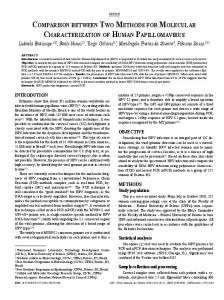
Figure 1: Vibroimpact system with rigid impact.
Generally saying, there is no clear criterion to say which constraint is rigid and which one is soft. The key is the stiffness coefficient-impact transience and its power is determined by the contacting bodies’ rigidity. It is considered that period of contact is vanishingly small and impact is instantaneous in systems with rigid constraints. The assumption about impact instantaneity is not true in systems with soft constraints; the impact duration is considerable. The main aim of this paper is to compare the possibility of two impact simulation methods used for two kinds of twodegree-of-freedom vibroimpact systems, systems with rigid and soft impacts. These methods are (I) impact simulation by boundary conditions with Newton’s restitution coefficient based on stereomechanic shock theory and (II) impact simulation by contact interaction force based on quasistatic Hertz contact theory. To achieve the main goal, three auxiliary tasks were posed: (1) to verify the possibility and evaluate the quality of impact simulation by linear elastic force for soft impact, (2) to evaluate the quality of impact simulation by Hertz force under both periodic and random external loadings for rigid impact, (3) to build the loading curves by parameter continuation method when impact-simulating by both methods and to compare these curves.
2. Design Models and Movement Equations of Vibroimpact Systems We consider that impacts between bodies at these vibroimpact systems occur with low velocities, without friction; that is, there are low speed impacts [5, 7]. The bodies are smooth, without roughness. We consider that the bodies are restricted by curve surfaces, so the real surface geometry may be approximated by “Hertzian” geometry. The first model of the vibroimpact system with rigid impact is formed by the main body and attached one, which can play the role of percussive or nonpercussive dynamic damper (Figure 1). Bodies are connected by linear elastic springs and dampers, and the main body is subjected to the action of periodical external force (except in Section 4.2): 𝐹 (𝑡) = 𝐹0 cos (𝜔𝑡 + 𝜑) .
(1)
Journal of Nonlinear Dynamics
3
Table 1: Parameters of vibroimpact system with rigid impact. Bodies’ characteristic Mass 𝑚𝑖 , kg Partial vibration frequency 𝜔𝑖 , rad s−1 Damping coefficient 𝜉𝑖 Initial distance between bodies 𝐷, m External loading amplitude 𝐹0 , N External loading frequency 𝜔, rad s−1 m2
Main 1000.0 6.283 0.036
𝑦1̈ = 𝑔𝜒 − 𝜔12 𝑦1 − 𝜔22 𝜒 [ℎ − (𝑦2 − 𝑦1 )]
y
c2
− 2𝜉1 𝜔1 𝑦2̇ + 2𝜉0 𝜔2 𝜒𝑦2̇ +
c0
k0
h
Attached 100.0 4.727 0.20 0.05 400.0 6.0
m1
F(t) k1
The origin of coordinate 𝑥 is chosen in the main body mass center in such state when all springs are not deformed. The initial distance between bodies in such state is 𝐷. The system structure is transforming while moving due to its dynamic states changes forced by the impact contacts between elements. Movement equations of the system have the form 𝑥1̈ = −2𝜉1 𝜔1 𝑥1̇ − 𝜔12 𝑥1 − 2𝜉2 𝜔2 𝜒 (𝑥1̇ − 𝑥2̇ ) 1 [𝐹 (𝑡) − 𝐹con (𝑥1 − 𝑥2 )] , 𝑚1
𝑥2̈ = −2𝜉2 𝜔2 (𝑥2̇ − 𝑥1̇ ) − 𝜔22 (𝑥2 − 𝑥1 − 𝐷) +
1 𝐹 (𝑥 − 𝑥2 ) , 𝑚2 con 1
1 𝐹 (𝑡) , 𝑚1
(3)
𝑦2̈ = −𝑔 + 𝜔22 [ℎ − (𝑦2 − 𝑦1 )] − 2 (𝜉2 + 𝜉0 ) 𝜔2 𝑦2̇ .
c1
Figure 2: Vibroimpact system with soft impact.
− 𝜔22 𝜒 (𝑥1 − 𝑥2 + 𝐷) +
and the table are beginning their joint vertical motion until the form is separated from the table. Being detached they are moving separately until the form falls down on the rubber block. Impact occurs and bodies again start moving together until the form is torn off the rubber block and so forth. The origin of coordinate 𝑦 is chosen in the platform table center in the state of its static equilibrium. Primary initial joint movement of the table and of the form is described by the equations
The vibroimpact movement is the separate bodies’ motion during the form tearing off from the rubber block and the joint bodies’ motion at the time of impact when form is falling down to the rubber block. This process is described by the equations: 𝑦1̈ = 𝑔𝜒 − 𝜔12 𝑦1 − 2𝜉1 𝜔1 𝑦1̇ + 2𝜉0 𝜔2 𝜒𝑦2̇ 𝐻 (𝑧) +
1 (𝐹 (𝑡) − 𝐹con (𝑦1 − 𝑦2 )) , 𝑚1
𝑦2̈ = −𝑔 − 2 (𝜉2 + 𝜉0 𝐻 (𝑧)) 𝜔2 𝑦2̇ +
1 𝐹 (𝑦 − 𝑦2 ) . 𝑚2 con 1
Here we introduced the standard indication: 𝜔1 = √𝑘1 /𝑚1 , 𝜔2 = √𝑘2 /𝑚2 , 𝜉0 = 𝑐0 /2𝑚2 𝜔2 , 𝜉1 = 𝑐1 /2𝑚1 𝜔1 , 𝜉2 = 𝑐2 /2𝑚2 𝜔2 , 𝜒 = 𝑚2 /𝑚1 , 𝐹con (𝑦1 − 𝑦2 ) is the contact interaction force; this member is absent in the movement equations when impact-simulating by boundary conditions, 𝑧 = ℎ − (𝑦2 − 𝑦1 ), and 𝐻(𝑧) is the Heaviside step function, and it is determined as
(2)
where 𝜔1 = √𝑘1 /𝑚1 , 𝜔2 = √𝑘2 /𝑚2 , 𝜉1 = (𝑐1 /2𝑚1 𝜔1 ), 𝜉2 = (𝑐2 /2𝑚2 𝜔2 ), 𝜒 = 𝑚2 /𝑚1 , and 𝐹con (𝑥1 − 𝑥2 ) is the contact interaction force which is modelling the impact and is acting only during the impact. This member is absent in the movement equations while the impact is simulated by the boundary conditions. Numerical parameters of this vibroimpact system are given in Table 1. The second model of vibroimpact system with soft impact is corresponding to the calculation scheme of vibroimpact platform, which is widely used in building industry for concrete mix compaction and concrete products forming (Figure 2). Platform table with mass 𝑚1 is secured to base by linear vibroisolation spring with stiffness 𝑘1 . Exiting external periodic force 𝐹(𝑡) (1) is generated by electric motors mounted under the table. Elastic rubber block (soft constraint) with thickness ℎ and linear stiffness 𝑘0 is attached to the table. Form with concrete with mass 𝑚2 is placed on this rubber block but is not fixed both to the block and to the table and thus can be torn off. Starting from equilibrium both the form
(4)
𝐻 (𝑧) = {
1, 𝑧 ⩾ 0; 0, 𝑧 < 0.
(5)
The contact force 𝐹con is modeling the impact and is acting only during the impact. It is described by formula (8) and (9) (see further) which contain Heviside function. Taking into account the significant influence of the resistance forces on the vibroimpact platform dynamics, three resistance forces are introduced: in the concrete mix, in the rubber block, and in the vibroisolation spring. The forces of friction, cohesion, and viscous resistance must be overcame at complex process of vibration condensation. This circumstance causes the investigation of viscous resistance forces and lowering of their importance at vibration influence. A series of investigators search this problem [31]. Resistance forces are assumed as proportional to the first degree of velocity with coefficients 𝑐2 , 𝑐0 , and 𝑐1 . Numerical parameters of vibroimpact platform are assumed as the normative literature prescribes [31] and are presented in Table 2. The values of damper coefficients are absent in [31]. Therefore we choose these coefficients in general use according to [32]. We have
4
Journal of Nonlinear Dynamics Table 2: Parameters of vibroimpact system with soft impact.
Platform table mass 𝑚1 , kg Form with concrete mass 𝑚2 , kg Rubber block stiffness 𝑘0 , 108 N m−1 Vibroisolation spring stiffness 𝑘1 , 106 N m−1 Rubber block thickness ℎ, m Damping coefficients In concrete mix 𝜉2 In rubber block 𝜉0 In vibroisolation spring 𝜉1 External loading amplitude 𝐹0 , 105 N External loading frequency 𝜔, rad s−1
7400.0 15000.0 3.0 1.278 0.0275 0.03 0.02 0.02 2.44 157.0
examined the influence of resistance forces on vibroimpact systems dynamics [33]. We have determined that the changes of damper coefficients 𝜉0 , 𝜉1 , and 𝜉2 in general use [32] does not change the platform table semiamplitudes practically and changed contact force value a little.
3. Impact Simulation by Boundary Conditions Impact simulated by boundary conditions at the moment of impact is considered to be instantaneous. Joint bodies’ motion during the impact is not taken into account; both bodies displacements are identical, and velocities are changing in jumps. Boundary conditions based on the stereomechanic shock theory for the first model with rigid impact (Figure 1) are as follows: 𝑥1+ = 𝑥1− ,
𝑥2+ = 𝑥2− ,
𝑥1̇+ =
(1 − 𝑒𝜒) 𝑥1̇− + 𝜒 (1 + 𝑒) 𝑥2̇− , 1+𝜒
𝑥2̇+ =
(1 + 𝑒) 𝑥1̇− + (𝜒 − 𝑒) 𝑥2̇− , 1+𝜒
(6)
where 𝑥1− , 𝑥2− , 𝑥1̇− , and 𝑥2̇− are both bodies’ displacements and velocities before the impact and 𝑥1+ , 𝑥2+ , 𝑥1̇+ , and 𝑥2̇+ are displacements and velocities after the impact. 𝑒 is Newton’s coefficient of restitution which is considered to be constant and is determined by materials of the colliding bodies. It does not depend on velocity of bodies’ rapprochement or on any other circumstances. It could take values ranging from zero to one. By the numerical integration of motion equations (2) we can obtain the movement picture—both system bodies’ displacements and their phase trajectories after the transient process (for 𝑒 = 1) (Figure 3). Numerical integration was fulfilled by Runge-Kutta 4th order method. It is seen that steady-state oscillation regime has one impact during period, and bodies’ velocities in the time of impact are changing in jumps. At the displacements plot we see well that the attached body 𝑚2 (thin line) jumps away from the main one 𝑚1 (thick line) during impacts.
The loading curves (Figure 4) were plotted for this model in a steady-state regime by parameter continuation method [34]. They show oscillation semiamplitude 𝐴 max dependence on the intensity parameter 𝜆 of external periodical loading presented as 𝐹 (𝑡) = 𝜆𝐹0 cos (𝜔𝑡 + 𝜑) .
(7)
Semiamplitude for nonharmonic oscillation is calculated by the formula 𝐴 max = 1/2(|𝑥max | + |𝑥min |). Let us pay attention to curves shape when 𝜆 is small. Let us compare Figure 4 with Figure 10. In Figure 4 there are no curves when 𝜆 < 0.57, while Figure 9 there are ones. Vibration regime at such 𝜆 values is unlocked. That is why we cannot find the semiamplitude values when impact-simulating by boundary conditions at impact moment because the impact is absent. The boundary conditions for the second model with soft impact (Figure 2) are similar to the ones for the first model (6). Both bodies’ displacements and their phase trajectories at 𝑒 = 1 are presented in Figure 5: (a) displacements 𝑦1 and 𝑦2 , (b) displacesments 𝑦1 and 𝑦2 − ℎ, (c) phase trajectories for platform table, and (d) phase trajectories for form which are corresponding to Figure 5(a). After transient period the vibration mode is found to be non-steady-state. Phase trajectories, plotted for the oscillation process without transient period, are demonstrating this fact. Maximum semiamplitude value for the platform table without transient period is 3.733 mm. This value is higher than real experimental value (up to 2.5 mm) which is given in [31]. Restitution coefficient 𝑒 applying less than 1 (𝑒 = 0.9 and less) does not make it possible to calculate the correct motion of the vibroimpact platform bodies. Figure 6 (𝑒 = 0.8) is confirming this assertion. We can see that the impact is absent and the motion is non-steady-state. This picture does not correspond to reality. Thus the impact modeling by boundary conditions for this model with soft impact does not give real motion picture and is found to be unsuccessful.
4. Impact Simulation by the Contact Interaction Force Contact interaction force between bodies 𝐹con is taken into consideration when the impact is modeled in such way. This force acts only during the impact. It may be described by different laws, both linear and nonlinear. 4.1. Linear Elastic Force. The usage of linear elastic force as a contact one [35, 36] could be shown for the second vibroimpact platform model (with soft impact). In this case it can be described as 𝐹con = 𝑘0 𝐻 (𝑧) ,
(8)
where 𝑧 = ℎ − (𝑦2 − 𝑦1 ) and 𝐻(𝑧) is the Heaviside function. Both platform bodies’ displacements are shown in Figure 7(a): 𝑦1 and 𝑦2 − ℎ. The contact force (black line) and
Journal of Nonlinear Dynamics
5
0.0
11
12
13
14
15
t (s)
(a)
ẋ 2 (m s−1 )
ẋ 1 (m s−1 )
x (m)
0.1
−0.1
1
0.5
0.2
0
0.5 0 −0.5
−0.5 −0.1
0.0 x1 (m)
0.1
−1 −0.1
(b)
0.1 x2 (m)
(c)
A max (m)
Figure 3: Movement picture for vibroimpact system with rigid impact in steady-state regime (impact simulation by boundary conditions, 𝑒 = 1).
particular, taking into account more completely and detailed colliding bodies’ mechanical characteristics:
0.9
𝐹con (𝑧) = 𝐾[𝐻 (𝑧) 𝑧 (𝑡)]3/2 ,
0.6 0.3 0.0
𝐾= 0
2
4 𝜆
6
8
Figure 4: Loading curves for vibroimpact system with rigid impact (impact simulation by boundary conditions, 𝑒 = 1).
external periodic loading (gray line) are shown at Figure 7(b), the phase trajectory for platform table in Figure 7(c), and for form with concrete in Figure 7(d). Due to impact softness the local deformations in contact zone are large. That is why the bodies “penetrate” one into another (Figure 7(a)). Vibroimpact oscillation regime reaches steadystate after a short transient process. The contact force maximum value and table vibration semiamplitude are, respectively, 7.5 ⋅ 105 N and 3.087 mm. Let us pay attention to the contact force graphic: it has the “bell” form in each impact. Such graphic form demonstrates long impact duration (compared with Figure 8). Impact duration characterizes the impact softness or hardness. When impact duration is large we cannot consider such impact as instantaneous. That is why the impact simulation by boundary conditions does not give good results: stereomechanic theory considers the impact to be instantaneous.
4.2. Nonlinear Hertz Force. The use of Hertz’s contact force for impact simulation is based on quasistatic Hertz’s theory [6, 7, 23–25, 37]. “Hertz first developed this quasistatic theory for elastic deformation localized near the contact patch and applied it to the collision of solid bodies with spherical contact surfaces” [7]. This theory takes into account only local deformations. The colliding bodies are smooth, without roughness, restricted by curve surfaces. Hertz’s law allows, in
𝛿1 =
𝑞 4 , 3 (𝛿1 + 𝛿2 ) √𝐴 + 𝐵
1 − 𝜇12 , 𝐸1 𝜋
𝛿2 =
(9)
1 − 𝜇22 , 𝐸2 𝜋
where 𝑧(𝑡) is the relative closing in of bodies, 𝑧(𝑡) = 𝑥1 −𝑥2 for the first model and 𝑧(𝑡) = ℎ−(𝑦2 −𝑦1 ) for the second model, 𝐴, 𝐵, and 𝑞 are constants characterizing the local geometry of the contact zone, 𝜇𝑖 and 𝐸𝑖 are, respectively, Poisson’s ratios and Young’s modulus for both bodies, and 𝐻(𝑧) is the Heaviside step function. Two types of the external load—periodic (1) and random—were considered for the first model with rigid impact. We used a model of stationary random process with hidden periodicity as a load during the numerical investigation of the vibroimpact system random oscillations. Single-sided spectral density of this process can be described by the formula [38] ̃ = 𝑆 (𝜔)
2 2𝜎ran 𝛼𝜃2 , 2 𝜋 (𝜔 ̃ 2 − 𝜃2 ) + 𝛼2 𝜔 ̃2
(10)
where 𝜎ran is the process variance, 𝜃 is the characteristic ̃ is the process frequency, 𝛼 is the correlation parameter, and 𝜔 frequency of special decomposition. Random load with the spectral density of this type is affecting, for example, ground transport machines [38], the deep-drilling equipment, and so forth. From the theory of random processes it is known [39] that the realization of a stationary random process (it is the random loading in our case) can be computed according to its spectral density by the formula 𝑛
̃𝑙 ) Δ𝜔, ̃ ̃𝑙 𝑡 + 𝛿𝑙 ) √2𝑆 (𝜔 𝐹 (𝑡) = ∑ cos (𝜔
(11)
𝑙=1
where 𝑛 is the harmonic components number and 𝛿𝑙 are the initial phases, which are random numbers uniformly
6
Journal of Nonlinear Dynamics
1 0.6 ẏ 1 (m s−1 )
y (m)
3.E − 02
1.E − 02
0.2
−0.2 −1.E − 02
1.2
1.3
1.4
−0.6 −5.5E − 03 −5.0E − 04 y1 (m)
1.5
t (s)
(c)
(a)
0.2 ẏ 2 (m s−1 )
y (m)
5.E − 03
0.E + 00
−5.E − 03
4.5E − 03
1.2
1.3
1.4
0
−0.2 3.1E − 02
1.5
t (s)
3.3E − 02 y2 (m)
(b)
(d)
Figure 5: Movement picture for vibroimpact system with soft impact (impact simulation by boundary conditions, 𝑒 = 1).
0.1
3.E − 02 ẏ 1 (m s−1 )
y (m)
2.E − 02 1.E − 02 0.E + 00 −1.E − 02
1.2
1.3
1.4
1.5
0
−0.1 −1.E − 03
y1 (m)
(a)
(c)
1.E − 03
0.1 ẏ 2 (m s−1 )
y (m)
1.E − 03
0.E + 00
−1.E − 03
0.E + 00
t (s)
1.2
1.3
1.4
1.5
0
−0.1 2.6E − 02
t (s)
2.7E − 02 y2 (m)
(b)
(d)
2.8E − 02
Figure 6: Movement picture for vibroimpact system with soft impact (impact simulation by boundary conditions, 𝑒 = 0.8).
Journal of Nonlinear Dynamics
7
ẏ 1 (m s−1 )
y (m)
3.E − 03 1.E − 03 −1.E − 03 −3.E − 03
2
2.05
2.1 t (s)
2.15
2.2
0.4 0.1 −0.2 −0.5 −3.E − 03
(c)
ẏ 2 (m s−1 )
(a)
F (H)
6.E + 05 3.E + 05 0.E + 00 −3.E + 05
2
2.05
3.E − 03 y1 (m)
2.1 t (s)
2.15
2.2
0.05
−0.15 5.0E − 04 1.5E − 03 2.5E − 03 y2 − h (m)
(b)
(d)
0.3
0.3
0.2
0.2 x (m)
x (m)
Figure 7: Movement picture for vibroimpact system with soft impact (impact simulation by elastic contact force).
0.1
0.1
0.0 −0.1
0.0 10
15
−0.1
20
(a )
(c)
25
30
4.E + 05 Fcon (H)
Fcon (H)
15
t (s)
4.E + 05
2.E + 05
0.E + 00
10
t (s)
10
15
2.E + 05
0.E + 00
10
15
20
t (s)
t (s)
(b)
(d)
25
30
Figure 8: Movement and contact force picture for vibroimpact system with rigid impact (impact simulation by Hertz force): (a) and (b) under harmonic loading; (c) and (d) under random loading.
distributed inside the interval 0 to 2𝜋. Random load characteristics were chosen as 𝑛 = 100, 𝜃 = 6 rad s−1 , 𝛼 = 5 rad s−1 , ̃ =0.2 rad s−1 . 𝜎ran = 4242.642 N, and Δ𝜔 The contact interaction force after Hertz’s law (9) depends both on colliding bodies materials and on local geometry of contact area. We consider that the surfaces of both bodies in the first model with rigid impact are spherical of radii 𝑅1 and 𝑅2 . Then constants 𝐴 and 𝐵 are found as 𝐴 = 𝐵 =
(1/2𝑅1 ) + (1/2𝑅2 ), and constant 𝑞 depends on relation 𝐴/𝐵, 𝑞(1) = 0.318 [23, 24]. Let us choose 𝑅1 = 2 m and 𝑅2 = 2 m. Then numerical parameters of vibroimpact system are given in Table 3. Main characteristics of the steady-state system vibrations under harmonic action are shown in Figures 8(a) and 8(b) and under stochastic one in Figures 8(c) and 8(d). Time dependence plots of the colliding bodies’ displacements
8
Journal of Nonlinear Dynamics e=1
e = 0.5 A max (m)
x (m)
0.2 0.1 0.0 −0.1 13
0.9 0.6 0.3 0.0
13.5
14 t (s)
14.5
15
Figure 9: Bodies’ displacements for vibroimpact system with rigid impact (impact simulation by boundary conditions at 𝑒 = 1 and 𝑒 = 0.5 and by Hertz contact force).
0
2
4 𝜆
6
8
Figure 10: Loading curves for vibroimpact system with rigid impact (impact simulation by Hertz force).
Table 4: Parameters of vibroimpact platform with soft impact. Table 3: Parameters of vibroimpact system with rigid impact. Bodies’ characteristic Young’s modulus 𝐸𝑖 , 1011 N m2 Poisson’s ratio 𝜇𝐼 Constants 𝐴 and 𝐵, m−1
Main 2.1 0.3
Attached 2.1 0.3 𝐴 = 𝐵 = 0.5
(Figures 8(a) and 8(c)) are clearly showing both the impact and rebound of the attached body from the main one after the impact. Time dependence plots of the contact forces acting at the moment of impact are presented in Figures 8(b) and 8(d). Therefore, the impact simulation by the contact interaction force which is varying according to the Hertz law gives good results for the model with rigid impact. It enables us to get the law of vibroimpact system motion for all timebases (including the impact period) both for harmonic and stochastic loadings. One of the principal restrictions for the force described by the Hertz law is the fact that it simulates elastic impact. We now will compare results obtained for the harmonic load in impact modeling by the contact interaction force and by the boundary conditions method for vibroimpact system with rigid impact. For restitution coefficient 𝑒 = 1 the results obtained with these methods are coinciding with an accuracy up to four decimal digits. For 𝑒 < 1 we observe a small deviation between the results. Figure 9 is showing the motion of system’s bodies (main body: thick line, attached one: thin line) for 𝑒 = 1 (black line) and 𝑒 = 0.5 (gray line). Displacements which were obtained at impact simulation by contact force are merging with curves for 𝑒 = 1. It is seen that even for a small restitution coefficient (𝑒 = 0.5), the difference between amplitudes does not exceed 17% for the main body and is lower than 12% for the attached one. Thus despite idealized assumptions about impact elasticity, the Hertz contact theory secures reliable results at the investigations of the vibroimpact systems oscillatory movement upon the whole timebase. For vibroimpact system with rigid impact the loading curves were created in Chapter 3 (see Figure 4). Those curves were created when impact was simulated by boundary conditions. Now we create the loading curves for this model with rigid impact under periodical external loading (7) in steadystate regime (Figures 10 and 11). Now impact is simulated by contact Hertz force. The curves are created by parameter
Form elasticity modulus 𝐸2 , 1012 N m2 Rubber block elasticity modulus 𝐸1 , 108 N m2 Form Poisson’s ratio 𝜇2 Rubber block Poisson’s ratio 𝜇1 Constants 𝐴 and 𝐵, m−1
2 3 0.3 0.4 𝐴 = 𝐵 = 0.1
continuation method. We want to compare the loading curves for the model with rigid impact, which were created when impact is simulated by these two methods. We see that the loading curves obtained by using impact simulation with the Hertz force and shown in Figure 10 are identical to curves obtained by impact simulation with boundary conditions and shown in Figure 4. Once more let us pay attention to curves shape when 𝜆 is small. Let us compare Figure 10 with Figure 4. In Figure 4 there were no curves when 𝜆 < 0.57, while in Figure 10 there are ones. Vibration regime at such 𝜆 values is unlocked. That is why we could not find the semiamplitude values when impact-simulating by boundary conditions at impact moment. Now when impact-simulating by contact interaction force, we can obtain the full picture of vibroimpact system bodies movement at the whole timebase when the impacts occur and when they do not occur. Such coincidence shows that both methods of impact simulation guarantee the identical results for vibroimpact system with rigid impact. We have pointed out before that the contact interaction force after Hertz’s law (9) depends both on colliding bodies’ materials and on local geometry of contact area. We consider that the surface of the upper body (form with concrete) in the second model with soft impact is a plane and the surface of the lower one (rubber block) is the sphere of big radius 𝑅. Then constants 𝐴 and 𝐵 are found as 𝐴 = 𝐵 = 1/2𝑅, and constant 𝑞 depends on relation 𝐴/𝐵, 𝑞(1) = 0.318 [23, 24]. Let us choose 𝑅 = 5 m. Then numerical parameters of vibroimpact platform are given in Table 4. The movement picture for the second model with soft impact under periodical external loading (1) is presented in Figure 11. Both platform bodies’ displacements are shown in Figure 11(a): 𝑦1 and 𝑦2 − ℎ. The contact force (black line) and external load (gray line) are shown at Figure 11(b), the phase trajectory for platform table—in Figure 11(c), and for form with concrete—in Figure 11(d). Due to impact softness the local deformations in contact zone are large. At Figure 11(a)
Journal of Nonlinear Dynamics
9
ẏ 1 (m s−1 )
y (m)
3.E − 03 1.E − 03 −1.E − 03 −3.E − 03
2
2.1
2.05
2.15
2.2
t (s)
0.4 0.1
−0.2 −0.5 3.E − 03 −3.E − 03 y1 (m) (c)
(a)
F (H)
0.E + 00
2
2.05
2.1
−3.E + 05
t (s)
(b)
2.15
2.2
ẏ 2 (m s−1 )
0.1 3.E + 05
0.05 0
−0.05
−0.1 −3.0E − 03 −2.0E − 03 y2 − h (m) (d)
Figure 11: Movement and contact force picture for vibroimpact platform with soft impact (impact simulation by Hertz force).
4.E − 03
A max (m)
3.E − 03 2.E − 03
(2, 1)
(1, 1)
(2, 2)
1.E − 03 0.E + 00 1500
11500
6500 m2 (kg)
Figure 12: The dependence of bodies’ vibration semiamplitudes for model with soft impact on upper body mass 𝑚2 .
we can see how the bodies “penetrate” one into another. The Hertz contact theory takes into account the local bodies’ deformations in contact zone. Figure 11 confirms this fact: we see the big deformation of soft rubber block and great penetration of the upper body into the lower. Let us see how the values of contact force and the platform table vibration semiamplitudes depend on sphere radius of rubber block. These values in steady-state regimes are given in Table 5. Table 5 shows that the decrease of rubber block sphere radius diminishes the contact force and the table semiamplitudes. Hence one can have influence on the values of contact interaction force and the platform vibration semiamplitudes by making the rubber block spherical and selecting this sphere radius. Comparing Figures 8(a), 8(b), 11(a), and 11(b), we can see that the single-impact steady-state 𝑇-periodical oscillation regime is achieved for both models. Contact force diagrams
(Figures 8(b) and 11(b)) are obviously demonstrating the impact instantaneity for the model with rigid impact and enough impact duration for the model with soft one. Comparison of results obtained at the impact simulation by elastic force (Section 4.1) and Hertz force shows that contact force maximum values and semiamplitude of platform table oscillation are the same at a quite large value of rubber block elasticity modulus, namely, at 𝐸1 = 12 ⋅ 108 N m−2 . At the same time the values obtained for the possibly smallest values 𝐸1 are closer to real values of platform table semiamplitudes (up to 2.5 mm) [31, 36] (Table 6). It is known, that the rubber elasticity modulus is less than the steels one by four orders. Hence for this model the Hertz force simulates impact better than the elastic one. We notice by the way that the value of rubber block elasticity modulus influences visibly the value of contact interaction force. It becomes larger when this elasticity modulus increases (Table 6). In [31] there are the values of platform table semiamplitudes which were obtained by an experimental study. These values are in diapason 2–2.5 mm. Our results by definite values of parameters (see Tables 5 and 6) are like them. We have fulfilled many numerical experiments [33, 40], which have given the positive results. For example we will give here the results of one experiment (Figures 12 and 13). We have investigated the dependence of vibration bodies’ semiamplitudes for vibroimpact system with soft impact on upper body mass 𝑚2 . The impact was simulated by Hertz contact force. It is shown in Figure 12. The mark (𝑛, 𝑘) means 𝑛𝑇 periodic vibration with 𝑘 impacts per cycle: (2, 1) 2𝑇periodical with 1 impact, (2, 2) 2𝑇-periodical with 2 impacts, and (1, 1) 𝑇-periodical with 1 impact per cycle. Here 𝑇 is the the period of external load. This numerical experiment has given adequate results.
10
Journal of Nonlinear Dynamics
0.E + 00 −2.E − 03 −4.E − 03
0.25 0.1 −0.05 −0.2 −0.35 −3.E − 03
ẏ 1 (m s−1 )
y (m)
2.E − 03
3.7
3.8
3.9
4.0
t (s)
(c)
F (H)
2.E + 05 3.8
3.9
−3.E + 05
4
ẏ 2 (m s−1 )
(a)
−5.E + 04 3.7
7.E − 04 y1 (m)
0.14 0.04
−0.06 −0.16 −1.8E − 03
t (s)
y2 − h (m)
(b)
1.8E − 03
(d)
Figure 13: Characteristics of (2,1) periodic movement for vibroimpact system with soft impact (𝑚2 = 4500 kg). 8.E + 05
1
6.E + 05
6.E + 05 Fcon (H)
Fcon (H)
1
8.E + 05
2
3
4.E + 05
2 4.E + 05
2.E + 05
2.E + 05
0.E + 00 0.0E + 00
0.E + 00 0.E + 00
3 1.0E − 02
2.0E − 02
3.0E − 02
t (ms)
(a)
2.E − 03 4.E − 03 [h − (y2 − y1 )] (m)
6.E − 03
(b)
Figure 14: Different contact forces dependence on time and bodies’ rapprochement for vibroimpact system with soft impact.
Let us compare elastic and Hertz’s forces more in detail. Figure 14 is showing contact force dependence from time and from bodies’ rapprochement during single impact period. Contact force is shown in three cases: elastic force (curves 1 in Figure 14) and Hertz’s force at 𝐸1 = 12 ⋅ 108 N m−2 (curves 2) and at 𝐸1 = 3 ⋅ 108 N m−2 (curves 3).
5. Conclusions (1) Comparison of two impact simulation methods used for two-degree-of-freedom nonlinear vibroimpact systems with rigid and soft impacts was fulfilled. These methods are (I) impact simulation by boundary conditions with Newton’s restitution coefficient based on stereomechanic shock theory and (II) impact simulation by contact interaction force based on quasistatic Hertz contact theory. We research low speed frictionless impacts. The bodies are smooth, without roughness, and are restricted by curve surfaces, so
the real surface geometry may be approximated by “Hertzian” geometry. The comparison shows the following: (i) both methods give coinciding results for vibroimpact system with elastic rigid impact under periodic external loading. These results were obtained by numerical integration of motion equations by Runge-Kutta 4th order method, (ii) loading curves built by parameter continuation method for system with rigid impact coincide completely with impact simulation by both methods, (iii) impact simulation by the first method for vibroimpact system with soft impact is not successful. The impact modeling by the second method is more preferable to such model. Linear elastic force can be used as contact
Journal of Nonlinear Dynamics
11
Table 5: Dependence of contact force maximum and platform table vibration semiamplitude on radius of rubber block. Rubber block radius 𝑅, m Constants 𝐴 and 𝐵, m−1 Contact force maximum 𝐹con , 105 N Platform table semiampl. 𝐴 max , mm
3.3 0.15 3.773 2.566
5 0.1 4.154 2.668
Table 6: Dependence of platform table semi-amplitudes and contact force maximum on rubber block elasticity modulus for vibroimpact platform with soft impact. Rubber block elasticity modulus 𝐸1 , 108 N m2 3 4.15 Hertz force maximum 𝐹con , 104 N 2.67 Platform table semi-amplitude 𝐴 max , mm
8 6.28 2.98
12 7.38 3.08
interaction force too, but the use of nonlinear Hertz contact force gives a better result. (2) Impact simulation by contact interaction force based on Hertz’s law has a series of advantages: (i) the method allows getting the full picture of vibroimpact system bodies movement at the whole timebase including the impact phase, (ii) it allows to get a contact force modification graph and its maximum value, (iii) constructions of parameter continuation method are getting simplified, (iv) Hertz force used as a contact force makes it possible to take into account more accurately and precisely the colliding bodies’ mechanical characteristics. A clear criterion of impact rigidity or softness does not exist. This criterion is determined by the impact duration, depending on how much momentarily it can be accepted. Therefore the authors consider that the impact simulation by Hertz contact interaction force is sufficiently successful for vibroimpact systems with impacts of any kind if all limitations with Hertz’s law used are observed.
References [1] V. L. Krupenin, “Impact and vibroimpact machines and devices,” Bulletin of Scientiffc and Technical Development, vol. 4, no. 20, pp. 3–32, 2009 (Russian), http://www.vntr.ru. [2] A. E. Kobrinsky and A. A. Kobrinsky, Vibro-Impact Systems, Nauka, Moscow, Russia, 1973, (Russian). [3] V. I. Babitsky, Theory of Vibro-Impact Systems and Applications, Springer, Berlin, Germany, 1998. [4] V. L. Ragul’skene, Vibroimpact Systems, Mintis, Vilnyus, Lithuania, 1974, (Russian). [5] A. P. Ivanov, Dynamics of Systems With Mechanical Impacts, International Education Program, Moscow, Russia, 1997, (in Russian). [6] R. A. Ibrahim, Vibro-Impact Dynamics: Modeling, Mapping and Applications, vol. 43 of Lecture Notes in Applied and Computational Mechanics, Springer, Berlin, Germany, 2009.
50 0.01 6.730 3.021
500 0.001 10.618 3.220
[7] W. J. Stronge, Impact Mechanics, Cambridge University Press, Cambridge, UK, 2000. [8] A. P. Ivanov, “Impact oscillations: linear theory of stability and bifurcations,” Journal of Sound and Vibration, vol. 178, no. 3, pp. 361–378, 1994. [9] Y. Ma, J. Ing, S. Banerjee, M. Wiercigroch, and E. Pavlovskaia, “The nature of the normal form map for soft impacting systems,” International Journal of Non-Linear Mechanics, vol. 43, no. 6, pp. 504–513, 2008. [10] O. Ajibose, M. Wiercigroch, E. Pavlovskaia, and A. Akisanya, “Influence of contact force models on the global and local dynamics of drifting impact oscillator,” in Proceedings of the 8th World Congress on Computational Mechanics (WCCM ’08) and 5th European Congress on Computational Methods in Applied Sciences and Engineering (ECCOMAS ’08), Venice, Italy, 2008. [11] S. R. Bishop, “Impact oscillators,” Philosophical Transactions of the Royal Society A, vol. 347, pp. 341–351, 1994. [12] Y. V. Mikhlin, A. F. Vakakis, and G. Salenger, “Direct and inverse problems encountered in vibro-impact oscillations of a discrete system,” Journal of Sound and Vibration, vol. 216, no. 2, pp. 227– 250, 1998. [13] F. Peterka, “Laws of impact motion of mechanical systems with one degree of freedom. I Theoretical analysis of n-multiple /1/n/-impact motions,” Acta Technica CSAV (Ceskoslovensk Akademie Ved), vol. 19, no. 4, pp. 462–473, 1974. [14] F. Peterka, “New type of forming machine,” in Nonlinear Dynamics of Production Systems, G. Radons and R. Neugebauer, Eds., Wiley-VCH, Weinheim, Germany, 2005. [15] B. Blazejczyk-Okolewska, K. Czolczynski, and T. Kapitaniak, “Dynamics of a two-degree-of-freedom cantilever beam with impacts,” Chaos, Solitons and Fractals, vol. 40, no. 4, pp. 1991– 2006, 2009. [16] G. S. Whiston, “Global dynamics of a vibro-impacting linear oscillator,” Journal of Sound and Vibration, vol. 118, no. 3, pp. 395–424, 1987. [17] A. B. Nordmark, “Non-periodic motion caused by grazing incidence in an impact oscillator,” Journal of Sound and Vibration, vol. 145, no. 2, pp. 279–297, 1991. [18] S. W. Shaw and P. J. Holmes, “A periodically forced piecewise linear oscillator,” Journal of Sound and Vibration, vol. 90, no. 1, pp. 129–155, 1983. [19] F. Peterka and O. Szollos, “In uence of the stop stiffness on impact oscillator dynamics,” in IUTAM Symposium on Unilateral Multibody Contacts, F. Pfeiffer and Ch. Glocker, Eds., pp. 127–135, Kluwer Academic, New York, NY, USA, 1999. [20] F. Peterka, “Dynamics of mechanical systems with soft impacts,” in IUTAM Symposium on Chaotic Dynamics and Control of Systems and Processes in Mechanics Solid Mechanics and Its Applications, G. Rega and F. Vestroni, Eds., vol. 122, pp. 313–322, 2005. [21] V. F. Zhuravlev, “Investigation of certain vibroimpact systems by the method of nonsmooth transformations,” Izvestiva AN SSSR Mehanika Tverdogo Tela (Mechanics of Solids), vol. 12, p. 2428, 1976.
12 [22] S. Foale and S. R. Bishop, “Bifurcations in impact oscillations,” Nonlinear Dynamics, vol. 6, no. 3, pp. 285–299, 1994. [23] W. Goldsmith, Impact: The theory and Physical Behaviour of Colliding Solids, Edward Arnold, London, UK, 1960. [24] K. L. Johnson, Contact Mechanics, Cambridge University Press, Cambridge, UK, 1985. [25] E. Rigaud and J. Perret-Liaudet, “Experiments and numerical results on non-linear vibrations of an impacting Hertzian contact. Part 1: harmonic excitation,” Journal of Sound and Vibration, vol. 265, no. 2, pp. 289–307, 2003. [26] L. P˚ust and F. Peterka, “Impact oscillator with Hertz’s model of contact,” Meccanica, vol. 38, no. 1, pp. 99–116, 2003. [27] Q. F. Wei, W. P. Dayawansa, and P. S. Krishnaprasad, “Approximation of dynamical effects due to impact on flexible bodies,” in Proceedings of the American Control Conference, vol. 2, pp. 1841–1845, July 1994. [28] S. Muthukumar and R. DesRoches, “A Hertz contact model with non-linear damping for pounding simulation,” Earthquake Engineering and Structural Dynamics, vol. 35, no. 7, pp. 811–828, 2006. [29] U. Andreaus and P. Casini, “Dynamics of SDOF oscillators with hysteretic motion-limiting stop,” Nonlinear Dynamics, vol. 22, no. 2, pp. 145–164, 2000. [30] B. Blazejczyk-Okolewska, K. Czolczynski, and T. Kapitaniak, “Classification principles of types of mechanical systems with impacts—fundamental assumptions and rules,” European Journal of Mechanics A, vol. 23, no. 3, pp. 517–537, 2004. [31] B. V. Gusev and V. G. Zazimko, Vibration Technology of Concretes, Budivelnyk, Kiev, Ukraine, 1991, (Russian). [32] B. G. Korenev and I. M. Rabinovich, Eds., Structure Dynamics. Handbook, Stroiizdat, Moscow, Russia, 1972, (Russian). [33] V. A. Bazhenov, O. S. Pogorelova, and T. G. Postnikova, “Effect of the structural parameters of the impact-vibratory system on its dynamics,” Strength of Materials, vol. 43, no. 1, pp. 87–95, 2011. [34] V. A. Bazhenov, O. S. Pogorelova, and T. G. Postnikova, “The development of continuation after parameter method for vibroimpact systems provided the impact is simulated by contact interaction force,” Strength of Materials and Theory of Structures, vol. 87, pp. 62–72, 2011 (Ukrainian). [35] A. V. Dukart, History of the Theory of the Impact Absorbers and Devices with Impact Elements and Their Application for the Vibroprotection of the Building Structures and Constructions [Doctor thesis ], 1993, (Russian). [36] V. A. Bazhenov, O. S. Pogorelova, T. G. Postnikova, and S. N. Goncharenko, “Comparative analysis of modeling methods for studying contact interaction in vibroimpact systems,” Strength of Materials, vol. 41, no. 4, pp. 392–398, 2009. [37] V. A. Bazhenov, O. S. Pogorelova, T. G. Postnikova, and O. A. Luk’yanchenko, “Numerical investigations of the dynamic processes in vibroimpact systems in modeling impacts by a force of contact interaction,” Strength of Materials, vol. 40, no. 6, pp. 656–662, 2008. [38] V. V. Bolotin, Random Vibrations in Elastic Systems, Nauka, Moscow, Russia, 1979, (Russian). [39] M. F. Dimentberg, Nonlinear Stochastic Problems of Mechanical Oscillations, Nauka, Moscow, Russia, 1980, (Russian). [40] V. A. Bazhenov, O. S. Pogorelova, and T. G. Postnikova, Dynamic Behaviour Analysis of Different Types Vibroimpact Systems., LAP LAMBERT Academic Publishing, Dudweiler, Germany, 2013, (Russian).
Journal of Nonlinear Dynamics
International Journal of
Rotating Machinery
Engineering Journal of
Hindawi Publishing Corporation http://www.hindawi.com
Volume 2014
The Scientific World Journal Hindawi Publishing Corporation http://www.hindawi.com
Volume 2014
International Journal of
Distributed Sensor Networks
Journal of
Sensors Hindawi Publishing Corporation http://www.hindawi.com
Volume 2014
Hindawi Publishing Corporation http://www.hindawi.com
Volume 2014
Hindawi Publishing Corporation http://www.hindawi.com
Volume 2014
Journal of
Control Science and Engineering
Advances in
Civil Engineering Hindawi Publishing Corporation http://www.hindawi.com
Hindawi Publishing Corporation http://www.hindawi.com
Volume 2014
Volume 2014
Submit your manuscripts at http://www.hindawi.com Journal of
Journal of
Electrical and Computer Engineering
Robotics Hindawi Publishing Corporation http://www.hindawi.com
Hindawi Publishing Corporation http://www.hindawi.com
Volume 2014
Volume 2014
VLSI Design Advances in OptoElectronics
International Journal of
Navigation and Observation Hindawi Publishing Corporation http://www.hindawi.com
Volume 2014
Hindawi Publishing Corporation http://www.hindawi.com
Hindawi Publishing Corporation http://www.hindawi.com
Chemical Engineering Hindawi Publishing Corporation http://www.hindawi.com
Volume 2014
Volume 2014
Active and Passive Electronic Components
Antennas and Propagation Hindawi Publishing Corporation http://www.hindawi.com
Aerospace Engineering
Hindawi Publishing Corporation http://www.hindawi.com
Volume 2014
Hindawi Publishing Corporation http://www.hindawi.com
Volume 2014
Volume 2014
International Journal of
International Journal of
International Journal of
Modelling & Simulation in Engineering
Volume 2014
Hindawi Publishing Corporation http://www.hindawi.com
Volume 2014
Shock and Vibration Hindawi Publishing Corporation http://www.hindawi.com
Volume 2014
Advances in
Acoustics and Vibration Hindawi Publishing Corporation http://www.hindawi.com
Volume 2014