Nov 19, 2014 - Wei Huang,1 Andon A. Rangelov,1,2 and Elica Kyoseva1. 1Engineering Product Development, Singapore University of Technology and ...
PHYSICAL REVIEW A 90, 053837 (2014)
Complete achromatic optical switching between two waveguides with a sign flip of the phase mismatch Wei Huang,1 Andon A. Rangelov,1,2 and Elica Kyoseva1 1
Engineering Product Development, Singapore University of Technology and Design, 20 Dover Drive, 138682 Singapore 2 Department of Physics, Sofia University, James Bourchier 5 Boulevard, 1164 Sofia, Bulgaria (Received 25 September 2014; published 19 November 2014) We present a two-waveguide coupler which realizes complete achromatic all-optical switching. The coupling of the waveguides has a hyperbolic-secant shape, while the phase mismatch has a sign flip at the maximum of the coupling. We derive an analytic solution for the electric field propagation using coupled-mode theory and show that the light switching is robust against small to moderate variations in the coupling strength and phase mismatch. Thus, we realize an achromatic light switching between the two waveguides. We further consider the extended case of three coupled waveguides in an array and pay special attention to the case of equal bidirectional achromatic light beam splitting. DOI: 10.1103/PhysRevA.90.053837
PACS number(s): 42.81.Qb, 42.82.Et, 42.79.Gn, 32.80.Xx
I. INTRODUCTION
II. MODEL OF TWO COUPLED WAVEGUIDES
The spatial light propagation in engineered coupled waveguide arrays is of fundamental importance to wave optics [1–3]. The electric field propagation in waveguide arrays can be accurately described within the coupled-mode theory [1–3], and the resulting optical wave equation describing the spatial propagation of monochromatic light in dielectric structures is remarkably similar to the temporal Schr¨odinger equation describing a quantum-optical system driven by an external electromagnetic field [4]. The simplest realization of a waveguide array consists of two identical evanescently coupled parallel waveguides. In this case, light is periodically switched between the waveguides throughout the evolution [3] in analogy to the quantum-optical Rabi oscillations [5]. Consequently, more complex waveguide configurations were designed to realize rich physical phenomena, and for several of them analytical solutions for the light propagation have been described in the literature [6–8]. In this work, we study the optical switching between two evanescently coupled planar waveguides whose coupling has a hyperbolic-secant shape, and the phase mismatch is constant, with a sign flip at the coupling maximum. We derive an analytic solution for complete light transfer (CLT), and we show that CLT is robust against variations in the experimental parameters; therefore, the technique is expected to find applications in achromatic light switching. Furthermore, we extend the model to three evanescently coupled waveguides in a planar array and show that starting from the middle waveguide, light can be equally split between the outer ones. We show that the light splitting is insensitive to fluctuations in the coupling and phase mismatch of the waveguides. Hence, this setup may find an important technological application as an achromatic light beam splitter. It is important to note that the coupling model which we consider here bears a close connection to the phase-jump models from quantum optics [9,10], where the phase jump is instead in the coupling rather than the detuning. Such a model would also realize CLT in the system of two coupled waveguides, but engineering a sign flip in the coupling would be a significant technological challenge.
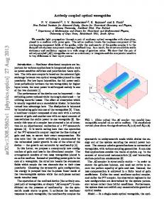
We consider two evanescently coupled planar optical waveguides, as shown in Fig. 1. In the paraxial approximation, the propagation of a monochromatic light beam in the waveguides can be analyzed in the framework of the coupled-mode theory (CMT) [1–3]. The corresponding evolution of the wave amplitudes can be described by a set of two coupled differential equations (in matrix form),
1050-2947/2014/90(5)/053837(5)
i
d C(z) = H(z)C(z), dz
(1)
which have the form of a Schr¨odinger equation [4], with z being the longitudinal coordinate. The components of the vector C(z) = [c1 (z),c2 (z)]T are the amplitudes of the fundamental modes in the two waveguides, and I1,2 = |c1,2 (z)|2 are the corresponding normalized light intensities. The operator H(z) describes the interaction between the waveguide modes and is explicitly given as � � β1 (z) �(z) . (2) H(z) = �(z) β2 (z) Here, βk (z) with k = (1,2) is the constant propagation coefficient of the kth waveguide, and �(z) is the variable coupling coefficient between the waveguides. We note that only the difference between the diagonal terms �(z) = [β2 (z) − β1 (z)]/2 is important, and it is called phase mismatch. We remove β1 (z) and β2 (z) from Eq. (2) by incorporating them as phases in amplitudes c1 (z) and c2 (z). Hence, Eq. (1) obtains the following form: � � �� � � −�(z) �(z) c1 (z) d c1 (z) = . (3) i �(z) �(z) c2 (z) dz c2 (z) In the next section we shall derive the solution to Eq. (3) for the step-sech model for which the coupling �(z) and phase mismatch �(z) are given by
053837-1
�(z) = �0 sech(z/L), � �0 (z < 0), �(z) = −�0 (z > 0).
(4a) (4b)
©2014 American Physical Society
WEI HUANG, ANDON A. RANGELOV, AND ELICA KYOSEVA
PHYSICAL REVIEW A 90, 053837 (2014)
here and described by Eq. (7) the corresponding parameters are α = �0 L, β = −α,
γ =
1 2
+ 12 i�0 L.
(9)
We then find that the solution to Eq. (7) is given by c1 (t) = AF (α, − α,γ ; t) + Bt 1−γ F (α + 1 − γ ,1 − α − γ ,2 − γ ; t), (10) where A and B are integration constants. Furthermore, using dt c2 (t) = [iei�t c˙1 (t) dz ]/ �(t) for the second amplitude, we obtain � α c2 (t) = i(1 − t)1−γ − A t γ F (1 + α,1 − α,1 + γ ,t) γ � 1−γ +B F (1 + α − γ ,1 − α − γ ,1 − γ ; t) . (11) α
FIG. 1. (Color online) Two evanescently coupled waveguides made of two slabs with refractive indexes n2 and n3 , embedded in a medium with an index of refraction n1 . Gaussian-shaped light is injected initially in the left waveguide, and at the end of the adiabatic evolution the light is achromatically switched to the right waveguide.
Here, L is the FWHM for the coupling �(z), and we have also chosen the point z = 0 to be the middle of the waveguides. Without loss of generality, the constants �0 and �0 are assumed to be positive. III. EXACT ANALYTICAL SOLUTION FOR THE SPATIAL LIGHT PROPAGATION
In order to derive the evolution of the wave amplitudes we rewrite Eq. (3) in the interaction picture, � � � �� � 0 �(z)e−iD(z) c1 (z) d c1 (z) = , i c2 (z) dz c2 (z) �(z)eiD(z) 0 � zf
(5)
with D(z) = zi �(z)dz. Then, we can decouple c1 (z) from c2 (z) by taking a second derivative in z, which gives � �˙ d2 d � − i� c1 (z) + �2 c1 (z) = 0. (6) c1 (z) − dz2 � dz The next step is to change the independent variable from z to t(z) = 12 [1 + tanh(z/L)], noting that t(−∞) = 0, t(0) = 12 , and t(+∞) = 1. We thus rewrite Eq. (6) for c1 (t(z)) using Eqs. (4) as � � 1 1 dc1 d 2 c1 − t + i�0 L + �20 L2 c1 = 0. (7) t(1 − t) 2 + dt 2 2 dt
The integration constants A and B depend on the initial conditions and are given by A = c1 (0), B = −iα
� (t,0) = F (α, − α,γ ; t), U11 (t,0) = U22
(14)
� U12 (t,0) = −U21 (t,0)
=
−iα 1−γ t F (α + 1 − γ ,1 − α − γ ,2 − γ ; t). 1−γ (15)
That is, the propagator from z → −∞ (t = 0) to z = 0 (t = 12 ) can be expressed simply as � � � � 1 a −b� , (16) U ,0 = b a� 2 where
� � 1 π 1/2 a = F α, − α,γ ; = γ (γ ) (ξ + η) , 2 2 � � iα 1 b = − F 1 + α,1 − α,1 + γ ; 2γ 2
−iπ 1/2 (γ ) (ξ − η) , 2γ with the exact form of the parameters ξ = η=
(17)
=
(18)
�1
1 � , (19) + 12 α + 14 i�0 L 34 − 12 α + 14 i�0 L
�3
(8)
where the overdot denotes a derivative in t. The solution to Eq. (8) is given in terms of a linear combination of two Gauss hypergeometric functions, F (α,β,γ ; t) and t 1−γ F (α + 1 − γ ,β + 1 − γ ,2 − γ ; t) [9–12]. For the system considered
(13)
Hence, for 0 � t � 12 (−∞ < z � 0), the wave amplitudes evolve according to C(t) = U(t,0)C(0), with
This equation has the same form as the Gauss hypergeometric equation [11,12]: t(1 − t)x¨ + [γ − (α + β + 1)t]x˙ − αβx = 0,
c2 (0) . (1 − γ )
(12)
4
4
1 � . (20) + 12 α + 14 i�0 L 34 − 12 α + 14 i�0 L
Using the time symmetry of Eq. (3) and taking into account that the only change for z > 0 is the sign of �(z), it is a simple
053837-2
COMPLETE ACHROMATIC OPTICAL SWITCHING BETWEEN . . .
PHYSICAL REVIEW A 90, 053837 (2014)
matter to show that the propagator for 0 � z < ∞ ( 21 � t � 1) reads � � � � a −b 1 U 1, . (21) = � a� b 2
1.0
Light intensities
0.8
The total evolution propagator U(1,0) = U(1, 12 )U( 12 ,0) is �
a 2 − b2 U(1,0) = 2 Re(ab� )
� −2 Re(ab� ) . (a 2 − b2 )�
(22)
Then the normalized light intensity in the second waveguide is given by I2 = |U12 (1,0)|2 = |2 Re(ab� )|2 .
0.6
0.4
0.2
(23)
Finally, we obtain the analytical expression for the light transfer between waveguides by substituting a, b, ξ , and η in Eq. (23): � � �� 2 � � � π �0 L iπ �0 L Im eiφ cos π α + , I2 = sech 2 2 (24) where � � � φ = 2 arg 14 − 12 α − 14 i�0 L 14 + 12 α + 14 i�0 L . (25)
0 -10
5
10
where the overdot denotes a derivative in the longitudinal coordinate z and � (28) ε(z) = �2 (z) + �2 (z), tan[2θ (z)] =
�(z) . �(z)
(29)
The amplitudes a1 (z) and a2 (z) in the adiabatic basis are connected with the diabatic (original) ones, c1 (z) and c2 (z), via the rotation matrix � � cos θ sin θ R(θ (z)) = , (30) − sin θ cos θ 1
10
0.75
5
0.5
0
hence, complete light switching between the two waveguides occurs. In Fig. 2 we illustrate a complete light switching between two waveguides for appropriately chosen interaction parameters (�0 � �0 ). In Fig. 3 we show the light switching between two coupled waveguides as a function of the phase mismatch and the coupling strength. Note that the light switching is reminiscent of an adiabatic passage with large regions of high-transition probability. However, the evolution of the light amplitudes under the step-sech model given in Eq. (4) is not adiabatic due to the discontinuity in the phase mismatch at z = 0.
0
FIG. 2. (Color online) Simulation of complete light switching between two evanescently coupled waveguides. We assume a sechshaped coupling �(z) = �0 sech(z/L) and a step-phase mismatch �(z) = �0 [1 − 2�(z)], where �(z) is the Heaviside step function. We select adiabatic parameters �0 = 50/L and �0 = 2/L.
Δ (units of 1/L)
(26)
-5
Distance z (units of L)
Recalling equation (9) and using the asymptotic expansions of ln( ) [11,12] in the limit of large coupling (�0 � �0 ), the light intensity in the second waveguide turns to � �2 � � �2 2�0 e−π�0 L/2 1 π �0 L + O2 ; I2 ≈ 2 0 2 1 − cos �0 2 �0 + �0
I2
I1
0.25
IV. ADIABATIC EVOLUTION
Below we present the adiabatic solution for the general model where the coupling of the waveguides is a symmetric pulse-shaped smooth function and the phase mismatch has a sign flip at the coupling maximum. We rewrite Eq. (1) in the adiabatic basis [13–15], �� � � � −ε(z) −i θ˙ (z) a1 (z) d a1 (z) i = , (27) a2 (z) dz a2 (z) i θ˙ (z) ε(z)
0
5
10
0
Ω0 (units of 1/L)
FIG. 3. (Color online) Final light intensity in the right waveguide from Fig. 1, given that the light is initially injected into the left waveguide. We numerically simulate Eq. (3) as a function of the maximum coupling strength �0 and the phase mismatch �0 from Eq. (4). The longitudinal coordinate z ranges from −10L to 10L.
053837-3
WEI HUANG, ANDON A. RANGELOV, AND ELICA KYOSEVA
PHYSICAL REVIEW A 90, 053837 (2014)
as (c1 (z),c2 (z))T = R(θ (z))(a1 (z),a2 (z))T . When the evolution of the system is adiabatic, |a1 (z)| and |a2 (z)| remain constant [13–15]. Mathematically, adiabatic evolution means that the nonadiabatic coupling terms θ˙ (z) in Eq. (27) are small compared to the diagonal terms and can be neglected. This restriction amounts to the following adiabatic condition on the interaction parameters [13–15]: ˙ − ��| ˙ |�� � |�2 + �2 |3/2 .
(31)
When the evolution is adiabatic, the solution for the propagator in the adiabatic basis from an initial coordinate zi to a final coordinate zf reads � � exp(−iS) 0 ad , (32) U (zf ,zi ) = 0 exp(iS) �z � where S = zi f �2 (z) + �2 (z)dz. The full propagator in the original basis for the model given in Eq. (4) reads U(zf ,zi ) = R(θ (zf ))U(zf ,0)R−1 (θ (z → +0)) −1
× R(θ (z → −0))U(0,zi )R (θ (zi )). (33) We note that the phase mismatch has a sign flip at z = 0, and hence, the evolution at that point is not adiabatic. However, the nonadiabatic evolution around this point is accounted for by the evolution matrix R−1 (θ (z → +0))R(θ (z → −0)). Now, if we take into account that �(zi ) = �(zf ) = 0 and �(z → −0) = −�(z → +0) = �0 , then the light intensity transfer to the second waveguide is I2 (zf ) = |U12 (zf ,zi )|2 =
�20 . �20 + �20
(34)
Thus, I2 (zf ) tends to 1 in the case where �0 � �0 and the light is completely transferred between the waveguides. We note that Eq. (34) not only is valid if the coupling is given as a hyperbolic-secant shape but also applies universally to every symmetric pulse-shaped smooth coupling [�(z) = �(−z)] that fulfills �(zi ) = �(zf ) = 0 together with a sign flip of the phase mismatch at the coupling maximum. V. ACHROMATIC BEAM SPLITTER
In this section we consider a symmetric array consisting of three coupled optical waveguides, as shown in Fig. 4. We assume that the middle waveguide is equally coupled to the two outer ones with coupling strength �(z), which is a function of the longitudinal coordinate z. Furthermore, the outer waveguides are assumed to have equal refractive indexes n3 and hence equal propagation coefficients β1 . The refractive index of the middle waveguide changes from n2 to n4 at the maximum of the coupling, which results in an abrupt change in its propagation coefficient β2 . The evolution of the light propagating in such a waveguide array is described by ⎡ ⎤ ⎡ ⎤⎡ ⎤ c1 (z) 0 �(z) 0 c1 (z) d ⎢ ⎥ ⎢ ⎥⎢ ⎥ i ⎣c2 (z)⎦ = ⎣�(z) �(z) �(z)⎦ ⎣c2 (z)⎦ , (35) dz c3 (z) c3 (z) 0 �(z) 0 where the phase mismatch is �(z) = β2 − β1 , c1,3 (z) are the light amplitudes in the outer waveguides (the system
FIG. 4. (Color online) Three evanescently coupled waveguides made of slabs with refractive indexes n2 , n3 , and n4 , embedded in a medium with a refractive index n1 . Gaussian-shaped beam light is injected initially in the middle waveguide, and at the end it is achromatically divided equally between the outer waveguides.
is completely symmetric), and c2 (z) is the amplitude in the middle waveguide. Notably, Eq. (35) is analogous to the Schr¨odinger equation describing a three-state quantum system subject to external electromagnetic field. It is well known that the Hamiltonian of Eq. (35) has a zero eigenvalue whose eigenvector is a dark state of the system; that is, it does not evolve under the evolution described by the Hamiltonian [16]. We introduce new basis states including the dark-state amplitude cd using the transformation √ ⎤⎡ ⎤ ⎡ √ ⎤ ⎡ 1/ 2 0 1/ 2 c1 (z) cb (z) ⎥ ⎢ ⎥ ⎢ ⎥⎢ 1 0 ⎦ ⎣c2 (z)⎦ , (36) ⎣c2 (z)⎦ = ⎣ 0 √ √ c3 (z) cd (z) 1/ 2 0 −1/ 2 where c2 (z) is the unchanged amplitude of the middle waveguide and cb (z) is the bright state amplitude involving an equal superposition of the amplitudes c1 (z) and c3 (z). Rewriting Eq. (35) in the new basis, we obtain √ ⎡ ⎤ ⎡ ⎤ ⎤⎡ cb (z) 0 �(z) 2 0 cb (z) √ d ⎢ ⎥ ⎢ ⎥ ⎥⎢ i ⎣c2 (z)⎦ = ⎣�(z) 2 �(z) 0⎦ ⎣c2 (z)⎦ . (37) dz cd (z) cd (z) 0 0 0 Indeed, we find that state cd (z) is decoupled from states cb (z) and c2 (z), and the three-state problem is reduced to a two-state one involving states cb (z) and c2 (z) only. In order to realize an achromatic beam splitter we take the following steps. Initially, we input the light in the middle waveguide with state amplitude c2 (z), and following the evolution described by Eq. (37), which is similar to that described in Secs. III and IV, the light is completely and robustly transferred into state cb (z), which is an equal superposition of the states of the outer waveguides. Thus, the light at the end of the waveguides will be split equally
053837-4
COMPLETE ACHROMATIC OPTICAL SWITCHING BETWEEN . . .
In Fig. 5 we show a numerical simulation of the light transfer in three evanescently coupled waveguides as described by Eq. (35). Starting from an initially populated middle waveguide, at the end of the evolution the light is equally split between the outer waveguides. For the numerical simulation we use realistic coupling parameters for different wavelengths from previous experimental papers [19–21].
1.0
Light intensities
0.8
I2
I2
0.6
I1=I3
PHYSICAL REVIEW A 90, 053837 (2014)
I1=I3
0.4
VI. CONCLUSIONS
0.2 0 -100 -50
0
50
100 -100 -50
0
50
100
Distance z [mm]
FIG. 5. (Color online) Illustration of equal light splitting between the two outer waveguides from Fig. 4, given that the light is initially injected into the middle waveguide. We assume a sechshaped coupling �(z) = �0 sech(z/L) and a step-phase mismatch �(z) = �0 [1 − 2�(z)]. In the left frame the coupling is �0 = 1.1 mm−1 , which corresponds to a wavelength of 633 nm [19,20]. In the right frame the coupling is �0 = 1.5 mm−1 , which corresponds to a wavelength of 850 nm [19,20]. In both cases the length of the waveguides is 20 cm, L = 15 mm, and �0 = 0.1 mm−1 .
between the outer waveguides, as shown in Fig. 4. The light switching, as shown in Fig. 3, is robust against variations in the coupling strength �(z) and phase mismatch �(z); therefore, the technique is expected to be achromatic. In contrast to previously suggested achromatic adiabatic multiple-beam splitters based on an analog of stimulated Raman adiabatic passage from quantum optics which are unidirectional [17–19], the above proposed beam-splitting device works in forward and backward directions of light propagation equally well. Hence, the described achromatic beam splitter is also bidirectional. [1] A. Yariv, IEEE J. Quantum Electron. 9, 919 (1973). [2] H. A. Haus and C. G. Fonstad, IEEE J. Quantum Electron. 17, 2321 (1981). [3] A. Yariv, Quantum Electronics (Wiley, New York, 1990). [4] S. Longhi, Laser Photonics Rev. 3, 243 (2009). [5] S. Longhi, Phys. Rev. A 71, 065801 (2005). [6] S. Longhi, J. Opt. B. 7, L9 (2005). [7] M. Ornigotti, G. Della Valle, T. Toney Fernandez, A. Coppa, V. Foglietti, P. Laporta, and S. Longhi, J. Phys. B 41, 085402 (2008). [8] F. Dreisow, A. Szameit, M. Heinrich, S. Nolte, A. T¨unnermann, M. Ornigotti, and S. Longhi, Phys. Rev. A 79, 055802 (2009). [9] N. V. Vitanov, New J. Phys. 9, 58 (2007). [10] B. T. Torosov and N. V. Vitanov, Phys. Rev. A 76, 053404 (2007). [11] A. Erd´elyi, W. Magnus, F. Oberhettinger, and F. G. Tricomi, Higher Transcendental Functions (McGraw-Hill, New York, 1953). [12] M. Abramowitz and I. A. Stegun, Handbook of Mathematical Functions (Dover, New York, 1964). [13] L. Allen and J. H. Eberly, Optical Resonance and Two-Level Atoms (Dover, New York, 1987).
In conclusion, we presented a two-waveguide coupler configuration which realizes complete achromatic all-optical switching that is robust to parameter fluctuations. We showed that the light propagation in the proposed waveguide coupler has an exact analytic solution which possesses the advantage of being valid for all values of the interaction parameters. In the limit of large coupling, complete light switching is achieved, which is insensitive to parameter fluctuations and is therefore achromatic. We furthermore showed that such a waveguide coupler can also be used for complete adiabatic light switching. An extension of this system to three coupled planar waveguides can be used as an achromatic beam splitter. Finally, the proposed waveguide coupler and beam splitter are experimentally feasible using photoinduced reconfigurable planar waveguides. The shapes and coefficients of propagation of such waveguides can be freely controlled by changing the local refractive index of the crystal with illuminating control light [19,20,22,23].
ACKNOWLEDGMENTS
We acknowledge financial support from Singapore University of Technology and Design Start-Up Research Grant, Project No. SRG EPD 2012 029 and SUTD-MIT International Design Centre (IDC) Grant, Project No. IDG31300102. [14] B. W. Shore, The Theory of Coherent Atomic Excitation (Wiley, New York, 1990). [15] N. Vitanov, M. Fleischhauer, B. Shore, and K. Bergmann, Adv. At. Mol. Opt. Phys. 46, 55 (2001). [16] N. V. Vitanov, J. Phys. B 31, 709 (1998). [17] F. Dreisow, M. Ornigotti, A. Szameit, M. Heinrich, R. Keil, S. Nolte, A. T¨unnermann, and S. Longhi, Appl. Phys. Lett. 95, 261102 (2009). [18] A. A. Rangelov and N. V. Vitanov, Phys. Rev. A 85, 055803 (2012). [19] C. Ciret, V. Coda, A. A. Rangelov, D. N. Neshev, and G. Montemezzani, Opt. Lett. 37, 3789 (2012). [20] C. Ciret, V. Coda, A. A. Rangelov, D. N. Neshev, and G. Montemezzani, Phys. Rev. A 87, 013806 (2013). [21] G. Della Valle, M. Ornigotti, T. Toney Fernandez, P. Laporta, S. Longhi, A. Coppa, and V. Foglietti, Appl. Phys. Lett. 92, 011106 (2008). [22] Ph. Dittrich, G. Montemezzani, P. Bernasconi, and P. G¨unter, Opt. Lett. 24, 1508 (1999). [23] M. Gorram, V. Coda, P. Th´evenin, and G. Montemezzani, Appl. Phys. B 95, 565 (2009).
053837-5