demodulation, a random body movement cancellation technique is developed to ... techniques. Index Terms â non-contact, Doppler radar sensor, respiration,.
Complex Signal Demodulation and Random Body Movement Cancellation Techniques for Non-contact Vital Sign Detection Changzhi Li, and Jenshan Lin University of Florida, Gainesville, FL, 32611, USA Abstract — A complex signal demodulation technique is proposed to eliminate the null detection point problem in noncontact vital sign detection. This technique is robust against DC offset in direct conversion system. Based on the complex signal demodulation, a random body movement cancellation technique is developed to cancel out strong noise caused by random body movement in non-contact vital sign monitoring. Multiple transceivers and antennas with polarization and frequency multiplexing are used to detect signals from different body orientations. The noise due to random body movement is cancelled out based on different patterns of the desired and undesired signals. Experiments by highly compact 5-6 GHz portable radar systems have been performed to verify these two techniques. Index Terms — non-contact, Doppler radar sensor, respiration, cardiopulmonary, vital sign, wireless, random body movement, complex signal, polarization multiplexing.
I. INTRODUCTION Remote non-contact vital sign detection based on microwave Doppler phase modulation effect has been studied for many years [1]-[6]. To achieve accurate and robust performance, researchers have spent great efforts for more than two decades on several technical challenges. As one of the main challenges, the null detection point problem was solved by the frequency tuning technique [4] in double-sideband system and by the arctangent demodulation in quadrature demodulation system [6]. However, the frequency tuning technique requires tuning the intermediate frequency once the distance between the antenna and the subject changes; and the arctangent demodulation is sensitive to DC offset thus requires complicated calibration of the DC offset. Another traditional way using quadrature demodulation is to decide in real time which channel is away from the null detection point [3]. In this paper, a complex signal reconstruction method is proposed to eliminate the null detection point problem. This technique is easy to be implemented, and does not require frequency tuning or the decision of which channel is out of the null detection point. Meantime, it is robust against DC offset, which can be removed by extracting the average signal from every time domain sliding signal window. Another main challenge for non-contact vital sign detection is the noise caused by the random body movement, which presents severe interference for accurate detection of respiration and heartbeat signal in practical applications. Since random body movement is comparable or even stronger than
978-1-4244-1780-3/08/$25.00 © 2008 IEEE
the weak vital sign signal, to some extent it is the main factor limiting broad applications of non-contact vital sensors. It will be shown in this paper that the different movement patterns of random body movement and physiological movement make it possible to remove the unwanted signal from the vital signs. The random body movement cancellation technique uses multiple antennas and transceivers to detect from the front and the back of the human body. Based on polarization and frequency multiplexing, signals detected from different body orientations are combined without interfering each other and noise caused by random body movement can be cancelled out. II. COMPLEX SIGNAL DEMODULATION For non-contact quadrature demodulation of vital sign, the signals detected by the I and the Q channels can be expressed and analyzed by spectral analysis as follows [5]:
I (t ) = cos( =
∞
4π xh (t )
λ
∞
∑ ∑J
(
+
4π xr (t )
λ
4π mr
4π mh
)cos(kωr t + lωht + φ ) (1.a)
λ ω ω = −2 [C10sin( r t )+C01sin( ht )+ k =−∞ l =−∞
k
λ
) Jl (
+φ)
]isinφ + 2 [C20cos(2ωr t )+C02 cos(2ωht )+ ]icosφ
Q (t ) = sin( =
∞
4π xh (t )
λ
∞
∑ ∑J
(
+
4π xr (t )
4π mr
)Jl (
+φ)
4π mh
)sin(kωr t + lωh t + φ ) (1.b)
λ = 2 [C10sin(ωr t )+C01sin(ωht )+ k =−∞ l =−∞
k
λ
λ
]icosφ + 2 [C20 cos(2ωr t )+C02 cos(2ωht )+ ]isin φ
where xh(t) = mh·sinωht, xr(t) = mr·sinωrt are the periodic body movements due to respiration and heartbeat, Jn is the Bessel function of the first kind, λ is the wavelength of wireless signal, Ф is the total residual phase accumulated in the circuit and along the transmission path. Cij = Ji(4πmr/λ)·Jj(4πmh/λ) determines the amplitude of every frequency component. From Eq. 1, the ratio of cosФ and sinФ determines the relative strength between the even order and the odd order harmonics. Therefore, the optimal/null detection point is determined by the residue phase Ф. For example, when Ф is close to 900, the fundamental frequency of respiration and
567
heartbeat signals dominates in the I channel while the second order harmonic of desired signals dominates in the Q channel, thus I is close to the optimal detection point and Q is close to the null detection point. When one of the two quadrature channels is close to an optimal detection point, the other channel should be close to the null detection point. One way to make reliable detection in quadrature demodulation system is to use arctangent demodulation [6] by calculating the total Doppler phase shift as arctan[I(t)/Q(t)]. The advantage is the ability to perfectly recover the vital sign information. However, this technique is sensitive to DC offset since the DC offset present in any channel will change the calculated phase shift. Unfortunately the DC offset for noncontact vital sign detection is not only produced by the electronic components, but also by the un-modulated reflected signal, i.e. signal reflected from stationary objects and other parts of the human body rather than the chest wall. Therefore, DC offset calibration is required once the experimental environment changes. In the complex signal demodulation method, the complex signal is software-reconstructed in real time by:
⎧ ⎡ 4π xh (t ) 4π xr (t ) ⎤⎫ S (t ) = I (t ) + j iQ(t ) = exp ⎨ j ⎢ + + φ ⎥⎬ λ λ ⎣ ⎦ ⎩ ⎭ = 2 j [C10sin(ωr t )+C01sin(ωht )+ ]ie jφ
i.e. when the subject is roaming toward one transceiver, it is moving away from the other transceiver.
λ2 , 7
Res 90
λ1 , ↔
Heart
0
Res 0
Body
I1 Q1
90
Q2 I2
DAQ
Re
S1 (t )
S 2 (t )
Im
Re Im
DAQ
B (t ) Spectral Analysis
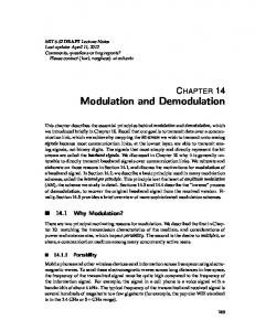
Fig. 1. System setup of random body movement cancellation technique. Two transceivers, one in front of and the other behind the human body, are transmitting and receiving signals with different polarization and wavelength. The transceiver block diagram is simplified such that components not closely related to the algorithm are not shown (e.g. low noise amplifier and high gain blocks).
A. Equations Applying the complex signal demodulation technique, the signal detected from the two transceivers can be expressed as:
(2)
⎤ ⎪⎫ ⎪⎧ ⎡ 4π mr1 sin(ωr t ) 4π mh1 sin(ωht ) 4π vt S1 (t ) = exp ⎨ j ⎢ + + + φ1 ⎥ ⎬ (3.a) λ1 λ1 λ1 ⎦ ⎭⎪ ⎩⎪ ⎣
where ejФ always has an amplitude of one and thus eliminates the weight of Ф in frequency domain. Applying complex Fourier transform to the signal S(t) for spectrum analysis, the residual phase Ф will not affect the relative strength between the odd order and the even order frequency components. The desired signal components (odd order tones) will always be present in the spectrum. Meantime, the DC components accumulated in the I and the Q channels only contribute to the DC term in the complex signal S(t), which can be easily removed by subtracting the complex average from the time domain sliding signal window before spectrum analysis.
⎧⎪ ⎡ 4π mr 2 sin(ωr t ) 4π mh 2 sin(ωh t ) 4π vt ⎤ ⎫⎪ + − + φ2 ⎥ ⎬ (3.b) S 2 (t ) = exp ⎨ j ⎢ λ2 λ2 λ2 ⎪⎩ ⎣ ⎦ ⎭⎪
+ 2 [C20cos(2ωr t )+C02cos(2ωht )+
]ie
jφ
III. RANDOM BODY MOVEMENT CANCELLATION Since the chest wall movement caused by respiration and heartbeat is very small, random body movement presents a serious noise source for non-contact vital sign detection. Fortunately, the noise from random body movement can be eliminated by recognizing the movement patterns. Shown in Fig. 1 is the block diagram of the random body movement cancellation technique. It should be noted that as the human body roams randomly in a certain direction (shown as the ‘Body’ arrow in Fig. 1), the heartbeat and the respiration cause the front and the back of the chest walls to move in the opposite directions. In the view of the two transceivers, the heartbeat-and-respiration-caused body movements are in phase, while the random body movements are out of phase,
978-1-4244-1780-3/08/$25.00 © 2008 IEEE
where v is a random variable representing the velocity of random body movement. It should be noted that the desired physiological signal presents a phase modulation in the baseband signal, while the random body movement presents a random frequency drift in the baseband signal. By multiplying the two complex signals, the output B(t) can be obtained as: B(t ) = S1 (t )i S2 (t ) ⎧⎪ ⎡ ⎛ m ⎛m m ⎞ m ⎞ = exp ⎨ j ⎢ 4π ⎜ r1 + r 2 ⎟ sin(ωr t ) + 4π ⎜ h1 + h 2 ⎟ sin(ωht ) λ2 ⎠ λ2 ⎠ ⎝ λ1 ⎪⎩ ⎣ ⎝ λ1 (4) ⎤ ⎪⎫ ⎛1 1 ⎞ + ⎜ − ⎟ 4π vt + φ1 + φ2 ⎥ ⎬ ⎝ λ1 λ2 ⎠ ⎦ ⎭⎪
⎧⎪ ⎡ 4π ( mr1 + mr 2 ) 4π ( mh1 + mh 2 ) ≈ exp ⎨ j ⎢ sin(ωr t ) + sin(ωht ) λ λ ⎪⎩ ⎣ +φ1 + φ2 ]}
where the approximation is valid because λ1 and λ2 are chosen to be close to each other. The operation in Eq. 4 corresponds to convolution and frequency shift in frequency domain, thus canceling the Doppler frequency drift and only keeping the periodic Doppler phase effects.
568
1
Front Back
0.8 0.6
5 2 -1 0
0.4
10 20 Time (s)
30
0.2 0 0
Normalized Spectrum
Body Move (cm)
Normalized Spectrum
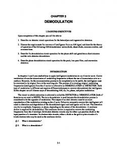
Simulations have been performed to verify this technique. The time domain signals detected from the front and the back of the human body are generated from Eq. 3, where the random body movement has a maximum of 5 cm displacement from the original body position as shown in the inset of Fig. 2 (a). The complex signal is obtained from Eq. 4. The spectrum of the signal detected in each channel and the spectrum of the complex signal are shown in Fig. 2. It is observed that the random body movement can be removed from the complex signal, and clear spectrum of desired signals can be obtained.
20
1
40
60 80 Beats/Min (a)
0.3
0.8
0.2
0.6
0.1
0.2
I
100
II
0 65
0.4
80
0 65
IV. EXPERIMENT RESULT Experiments have been performed in lab environment to verify the complex signal demodulation and the random body movement cancellation techniques. The measurements were performed by 5 – 6 GHz portable radars, which integrate the quadrature transceiver, the two-stage baseband amplifier, and the power management circuit on a single Rogers printed circuit board (RO4350B) with a size of 6.8 cm × 7.5 cm. The amplified baseband output signals were sampled by a 12 bit multifunction data acquisition module (DAQ) and were fed into a laptop for real time signal processing by LabVIEW. Fig. 3 shows the antennas and the identical transceivers used for experiments.
120
III
0.2
0.1
frequency results in a large difference in baseband frequency for vital sign detection, which is typically no higher than several hertz.
0.1
70
75
70
75
40
60 80 Beats/Min (b)
80
0 65
70
75
80
0.2 0 0
20
100
120
Fig. 2. Simulation result of random body movement cancellation. (a) Spectrum detected from the front and the back of the subject, the body is moving randomly as shown in the inset. (b) Spectrum recovered by the random body movement cancellation technique when DC offset is calibrated out; inset: heartbeat spectrum when DC offset/signal amplitude = 0.2 (I), 0.4 (II), and 0.6 (III);
However, the random body movement cancellation technique is not immune from DC offset. The inset of Fig. 2 (b) shows the spectrum around the heartbeat frequency when DC offset is present in the system. As the amplitude of DC offset increases from 20% to 60% of the desired signal amplitude, more noise is added to the spectrum until the desired signal is completely overwhelmed by noise. B. Polarization and Frequency Multiplexing Since the two transceivers are facing each other, it is important to prevent signal of one unit from saturating or interfering the receiver link of the other unit. Therefore, patch array antennas with orthogonal polarization pattern are used for the two units. And free running VCOs are used for the two transmitters so that λ1 and λ2 are close to each other but always have a slight difference because the system does not incorporate any phase-locked-loop. Therefore, the signal from one transceiver can be easily rejected by the other transceiver in the baseband, because the small difference in the carrier
978-1-4244-1780-3/08/$25.00 © 2008 IEEE
Fig. 3. Two identical transceivers used in experiments. Inset: the antenna used for each transceiver. Note that one transceiver uses vertically polarized antenna array, while the other uses horizontally polarized antenna array.
A single transceiver was used to illustrate the complex signal demodulation technique. Fig. 4 shows the measurement results obtained by slightly adjusting the subject-to-antenna distance. Three typical cases are reported here as: (a) the I channel was at the optimal detection point while the Q channel was at the null detection point; (b) the Q channel at the optimal while the I channel at the null detection point; (c) both channels are at the midpoint between the null and the optimal. It is observed that although the I and the Q channel will change from one state to another (i.e. optimal/null detection) as the distance between the antenna and the subject changes, the reconstructed complex signal always has a stable spectrum without the null detection point problem. Figure 5 shows a measurement result when the two transceivers were used to verify the random body movement cancellation technique. During experiment, the subject under test was gently changing position in a chair, so that the noise of random body movement was emphasized. Since the physiological movement at the back chest wall is weaker than
569
0.2
Volt
0.2 0
I
-0.2
CSD Spectrum
I/Q Spectrum
0
2
4
6 8 Time (Second)
12
1
0
2
0
4
6 8 Time (Second)
10
-0.2 12
1
20
40
60 80 Beats/Min
100
120
0
0
20
40
60 80 Beats/Min
100
120
0
1
1
0.5
0.5
0.5
0
20
40
60 80 Beats/Min
100
120
0
4
6 8 Time (Second)
Q
10
12
I
0.5
1
0
2
1
0.5
0
0
Q
I 0.5
I
0
Q
-0.2 10
Q
0.2
0
0
20
40
60 80 Beats/Min
100
120
0
0
20
40
60 80 Beats/Min
100
120
0
20
40
60 80 Beats/Min
100
120
(a) (b) (c) Fig. 4. Measurement results of complex demodulation, with the time domain signal recorded in the top figures, the I/Q channel spectrum recorded in the middle figures, and the spectrum from the complex signal demodulation (CSD) in the bottom figures. (a) I: optimal detection, Q: null detection; (b) I: null detection, Q: optimal detection; (c) I, Q: both at the midpoint between the optimal and the null detection points.
that at the front chest wall, the noise completely overwhelmed the physiological signal from the back, and only overwhelmed the heartbeat signal from the front. When the proposed technique was applied to combine the signals detected from the front and the back of the human body, it is shown in Fig. 5 (b) that the heartbeat signal was recovered.
Spectrum
1 Front Back
0.5
Combined Spectrum
0 0
ACKNOWLEDGEMENT The authors wish to acknowledge the Hittite, RFMD, and Rogers for providing microwave integrated circuits and laminate substrates. REFERENCES
20
40
1
60 80 Beats/Min (a)
100
120
Recovered Heartbeat
0.5
0 0
detection. Experiments have been performed to successfully demonstrate these techniques.
20
40
60 80 Beats/Min (b)
100
120
Fig. 5. Detected baseband spectrum by the random body movement cancellation technique. (a) Complex signal demodulated spectrum measured from the front and the back of the human body; (b) Output spectrum by the random body movement cancellation technique, the heartbeat information is successfully recovered;
V. CONCLUSION A complex signal demodulation technique is proposed in this paper to eliminate the null detection point problem for non-contact vital sign detection. Based on this complex signal demodulation, the random body movement cancellation technique is developed to cancel out random body movement, which is a serious problem for non-contact vital sign
978-1-4244-1780-3/08/$25.00 © 2008 IEEE
[1] J. C. Lin, “Microwave sensing of physiological movement and volume change: A review,” Bioelectromagnetics, vol. 13, pp. 557-565, 1992. [2] K. M. Chen, Y. Huang, J. Zhang, and A. Norman, “Microwave life-detection systems for searching human subjects under earthquake rubble and behind barrier,” IEEE Trans. Biomed. Eng., vol. 47, pp. 105-114, Jan. 2000. [3] A. D. Droitcour, O. Boric-Lubecke, V. M. Lubecke, J. Lin, and G. T. A. Kovac, “Range correlation and I/Q performance benefits in single-chip silicon Doppler radars for noncontact cardiopulmonary monitoring,” IEEE Trans. Microwave Theory and Techniques, vol. 52, pp. 838-848, March 2004. [4] Y. Xiao, J. Lin, O. Boric-Lubecke, and V. M. Lubecke, “Frequency Tuning Technique for Remote Detection of Heartbeat and Respiration Using Low-Power Double-Sideband Transmission in Ka-Band,” IEEE Trans. Microwave Theory and Techniques, vol. 54, pp. 2023-2032, May, 2006. [5] C. Li, Y. Xiao, and J. Lin, “Experiment and Spectral Analysis of a Low-Power Ka-Band Heartbeat Detector Measuring from Four Sides of a Human Body,” IEEE Trans. Microwave Theory and Techniques, vol. 54, no. 12, pp. 4464-4471, December 2006. [6] B. Park, O. Boric-Lubecke, and V. M. Lubecke, “Arctangent demodulation with DC offset compensation in quadrature Doppler radar receiver systems”, IEEE Trans. Microwave Theory and Techniques, vol. 55, pp. 1073-1079, May 2007.
570