Component-Based Design Approach for Multicore SoCs1 W. Cesário, A. Baghdadi, L. Gauthier, D. Lyonnard, G. Nicolescu, Y. Paviot, S. Yoo, A.A. Jerraya
M. Diaz-Nava
TIMA Laboratory, SLS Group 46, av. Félix Viallet 38031 Grenoble Cedex - France
STMicroelectronics AST Grenoble Lab 12, rue Jules Horowitz, BP217 38019 Grenoble Cedex - France
{Wander.Cesario,Ahmed.Jerraya}@imag.fr
[email protected]
ABSTRACT This paper presents a high-level component-based methodology and design environment for application-specific multicore SoC architectures. Component-based design provides primitives to build complex architectures from basic components. This bottomup approach allows design-architects to explore efficient custom solutions with best performances. This paper presents a high-level component-based methodology and design environment for application-specific multicore SoC architectures. The system specifications are represented as a virtual architecture described in a SystemC-like model and annotated with a set of configuration parameters. Our component-based design environment provides automatic wrapper-generation tools able to synthesize hardware interfaces, device drivers, and operating systems that implement a high-level interconnect API. This approach, experimented over a VDSL system, shows a drastic design time reduction without any significant efficiency loss in the final circuit.
Categories and Subject Descriptors C.3 [SPECIAL-PURPOSE AND APPLICATION-BASED SYSTEMS]: Microprocessor/microcomputer applications, Real-time and embedded systems.
General Terms Design, Experimentation, Standardization.
Keywords Multicore System-on-Chip, Component-based design, HW/SW interfaces abstraction.
1. INTRODUCTION The ITRS roadmap [1] predicts that by 2004 70% of ASICs will include at least one embedded instruction-set processor, which means that most ASICs will be Systems-on-Chip (SoC). Some existing designs confirm and strengthen this prediction, many applications include several processors with different instructionsets: mobile terminals (e.g. GSM [2]), set-top boxes (e.g. Permission to make digital or hard copies of all or part of this work for personal or classroom use is granted without fee provided that copies are not made or distributed for profit or commercial advantage and that copies bear this notice and the full citation on the first page. To copy otherwise, or republish, to post on servers or to redistribute to lists, requires prior specific permission and/or a fee. DAC 2002, June 10-14, 2002, New Orleans, Louisiana, USA. Copyright 2002 ACM 1-58113-461-4/02/0006…$5.00.
PNX8500 from Philips [3]), game processors (e.g. PlayStation2 from Sony [4]) and network processors [5]. Most system and semiconductor houses are developing platforms involving several cores (MCU, DSP, IP, etc) and sophisticated communication interconnects (hierarchical bus, TDMA-based bus, point-to-point connections and packet-routing switches) on a single chip. The trend is moving now to interconnect standard components in the same fashion performed for boards few years ago. This evolution is creating several breaking points in the design process and new challenges for the EDA industry: 1. Systems are the more and more complex: communication cannot be specified manually at the register-transfer level (RTL) as before without introducing many errors. At this level, bus structures (data, address and control) and clock cycles need to be detailed to verify logical and electrical constraints. However, this level is not well adapted to check communication protocols because this would be too much time consuming. By these reasons, higher abstraction levels, to model and verify the interconnection between components, are required to master the complexity: reduce design time and errors. 2. SoCs will include many processors with different instruction-sets to execute dedicated functions in order to increase the flexibility of the whole system. The complexity of the code will become higher than the hardware part and will require, in the near future, several hundreds or thousands person-years [1]. This software will not be programmed at the assembler level as today. 3. Complex, on-chip, hardware/software interfaces are required to implement an application-specific communication interconnect. The hardware (microprocessor interfaces, bank of registers, memories) and software (drivers, operating systems) elements required to perform the communication protocols need to be adapted to the communication interconnect according to the type of core. This paper presents a systematic approach for the assembling of application-specific SoC and the definition of a composition model to abstract the interconnection between hardware (cores) and software (tasks) components. Section 2 introduces the basic concepts for complex SoC design and the component-based approach. Section 3 details a new component-based specification model and the design flow that enables multicore SoC design at a higher level than RTL. Section 4 presents the application of this flow onto the design of a VDSL circuit and the analysis of the results. Finally, section 5 concludes this paper.
1
This research was partially funded by MEDEA+ project A508.
2. BASICS: SYSTEM-ON-CHIP DESIGN The expression SoC is used to designate an ASIC that combines heterogeneous components (CPUs, DSPs, IPs, memories, buses, etc.) on the same chip. This is similar to what we were used to see on system boards.
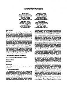
2.1 SoC Architecture The classic literature about multiprocessor systems provides all the basic concepts used in this work [7][8], but it is too general to be efficient for SoCs. Figure 1 shows a typical multicore SoC architecture with heterogeneous processors and the on-chip communication interconnect. A key difference with classic computer architecture is that this model distinguishes (based on their utilization) two kinds of processors (CPUs): those used to run the end application and those dedicated to execute specific functions that could have been designed in hardware. The programming and interfacing of these two kinds of processors are quite different, as we will explain later. CPU core (run application)
IP (HW function, memory)
Dedicated CPU (DSP)
Communication interconnect
Figure 1. A typical multicore SoC architecture Additionally, dedicated processors require application-specific communications and memory schemes due to performance optimization reasons. These specific architecture optimizations are generally related to the application domain. For instance, application-specific interfaces are required to respect tight resource/performance constraints (e.g. area, power, runtime, etc.).
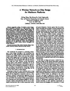
2.2 Software Organization Each kind of embedded processor employs a different software organization. The application software is generally organized as a stack of layers on top of the hardware as shown in Figure 2a. Application SW
Functions realized in SW
Programming API
Specific API
Standard OS services
Custom OS
SW support package (drivers)
Drivers
Hardware
Hardware
(a) Application software stack
(b) Functional software stack
Figure 2. Software organization The lowest software layer provides the drivers and the low-level architecture controllers. This is also called the software support package, and is generally provided by the SoC design team. The upper layers, OS services and SW application layer are provided by the application designer. The OS layer generally reuses an existing embedded OS, which may be customized to the application. The top layer is application-specific software that may be designed using high-level languages and code generation techniques. Application coding is not part of the SoC design and will be omitted in the rest of this paper. Presently, the software running on the dedicated processors is written in Assembly/C. When multitasking and complex I/O are
required, specific code is provided to perform scheduling and to manage I/O. This code is generally mixed with the functional code, and there is no separated OS layer. This low-level programming is one of the main bottlenecks in SoC design. Additionally, this scheme lacks flexibility/portability and makes it difficult to change the hardware part without a complete redesign. One of the main contributions of this work is to consider higherlevel programming approach for dedicated software (often-called firmware). Each dedicated CPU will use a software stack (see Figure 2b). Of course, for code size and performance reasons, it will not be realistic to use any existing generic OS as isolation layer. In this case, a custom OS supporting an application-specific program interface (API) is required. Custom OS design automation is a new research area brought by SoC design [9]. With this scheme, both dedicated and application software can be written independently from the hardware implementation. Another benefit of this approach is that dedicated software can be independent from hardware/software frontiers on architecture components and OS choices. Finally, the main advantage of the work presented in this paper is to allow this level of flexibility/portability without any loss of performance.
2.3 SoC Design Methods Currently, most SoC designs start at the RT-level for the hardware interfaces and at the ISA level for the dedicated software components. Validation of the overall design uses co-simulation techniques that generally combine one hardware simulator and one or several instruction-set simulators (ISS). As explained in [10], two design automation approaches are competing to improve productivity: top-down and bottom-up approaches. The most popular top-down approaches are: synthesis from system level models [11][12][13] and platform-based design [14][15]. These approaches start with an architectural solution, target architecture or architecture platform. In contrast, the bottom-up approach, also called component-based design, starts with a set of components and provides a set of primitives to build application-specific architectures and communication APIs. The key idea of component-based design is to increase the abstraction level when designing component interconnections. Even if this approach does not provide much help on automating the architecture exploration phase, it may provide a considerable reduction of design time for hardware/software communication refinement and component integration, and facilitate IP reuse. The key point in such a flow is the use of an abstract architecture where communication is separated from the component on the hardware side and from the functions on the software side. This abstract architecture may be used by the software programmer as an API. On the other side, the abstract architecture may use hardware components through an abstract API. This is generally called separation between communication and computation for component-based design [15].
2.4 Component-based Approaches In component-based SoC design [16], the goal is to enable the integration of heterogeneous processors and communication protocols by using abstract interconnections. Behavior and communication must be separated in the system specification. Thus, system communication can be described at a higher-level and refined independently of the behavioral of system.
There are two component-based design approaches: usage of a standard bus protocol [17] and usage of a standard component protocol [18][19]. IBM defined a bus architecture called CoreConnect that adopts the first approach [17]. To connect heterogeneous components to the bus architecture, a wrapper is designed to adapt the protocol of each component to CoreConnect protocols. VSIA promotes the second approach with VCI and FI as standard component protocols [18]. In this case, the designer can choose a bus protocol and then design wrappers to interconnect using this protocol. [20] also present methods for onchip network communication design in the case of multicore SoCs. This paper introduces a new concept, called virtual architecture, to cover both approaches listed above. Recently, several commercial tools are trying to deal with the component-based design concept. CoWare presents the tool N2C [21], Cadence presents VCC (Virtual Component Codesign) [14], Sonics presents Silicon Backplane µNetwork [19]. Still, designers are not able to obtain significant reduction in system design cycle and optimized multicore architectures. This is mainly due to the non-separation of functional and application software and to the non-availability of custom OS generation tools.
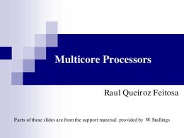
3. COMPONENT-BASED DESIGN This section introduces a high-level system design methodology for multicore SoC design using a communication refinement approach for virtual components. The system is described as a set of virtual components interconnected via channels. A virtual component consists of a wrapper and an internal component (or module). The internal component corresponds to a software task or a hardware function. The wrapper adapts accesses from the internal component to the external channels connected to the virtual component. The internal component and external channel(s) can be different in terms of: (1) communication protocol, (2) abstraction level, and (3) specification language. Depending on the difference, the functionality/structure of the wrapper is determined and automatically generated.
3. virtual channel: grouping several channels having a logical relationship (e.g. multiples nets belonging to the same communication protocol). M2 M1
M3 blackbox
: wrapper : virtual component
: module : task
: virtual port
: configuration parameters
: virtual channel
Figure 3. The virtual architecture model For system refinement, this model needs to be annotated with architecture configuration parameters (e.g. protocol and physical addresses of ports). This model is not synthesizable/executable because the behavior of wrappers is not described. The main goal of this design methodology is to generate automatically these wrappers, in order to produce a detailed architecture that can be both synthesized and simulated.
3.2 The Generic Architecture Model When defining this model our goal was to have a generic model where both computation and communication may be customized to fit the specific needs of the application. For computation, we may change the number and kind of components and, for communication, we can select a specific communication scheme. The architecture model is suitable to a wide domain of applications; more details can be found in [24]. CPU1 task1 ... taskn
3.1 Virtual Architecture Model The virtual architecture, also called macro architecture, represents a system as an abstract netlist of virtual components (see Figure 3). Each virtual component has a wrapper that is composed of a set of virtual ports [22]. A virtual port has internal and external ports. There could be an n to m (n and m are natural numbers) correspondence between the internal and the external ports. Internal and external ports are not directly connected because they can use different communication protocols and/or transmit signals at different abstraction levels. For this reason, in some cases the wrapper will do a conversion between different internal/external communication protocols and/or abstraction levels. Virtual channels hide many details of communication protocols, for instance, FIFO communication is realized using high-level communication primitives (e.g. put and get). In our design flow, the virtual architecture is described using an extension of SystemC. Three new concepts are used: 1.
virtual module: consists of a module and its wrapper;
2. virtual port: groups the corresponding internal and external ports having a conversion relationship. A wrapper may be composed of an hierarchy of several virtual ports;
OS HW/SW wrapper Wrapper
HW IP Wrapper
HW wrapper
Physical communication network
Figure 4. Generic architecture model for multicore SoC We use a generic multicore SoC architecture where processors are connected to communication networks via wrappers (see Figure 4). In fact, HW processors are separated from the physical communication network by wrappers that act as communication coprocessors or bridges. Such a separation is necessary to free the processors from communication management and it enables parallel execution of computation tasks and communication protocols. Software tasks need also to be isolated from hardware through an OS that plays the role of SW wrapper. As shown in Figure 5, the wrapper is made of a software part and a hardware part. On the hardware side, the internal architecture of the wrapper consists of a processor adapter, a channel adapter, and an internal bus. The number of channel adapters depends on the number of channels that are connected to the corresponding virtual module. On the software side, wrappers provide the
implementation of high-level communication primitives (API) used in the software module and the drivers to control the hardware. If required, the software wrapper will also provide sophisticated OS services such as task scheduling and interrupt management. Task1() {... _write(d); yield2sched();
SW wrapper
Software module
FIFO Yield write(…) schedule Task Int. schedule I/O Write ... ... Reg(…)
Processor adapter
...
API services
FIFO
ib_it ib_data
CA
ib_enable
CA
drivers
...
(a) software wrapper
(b) hardware wrapper
Figure 5. HW/SW wrapper architecture
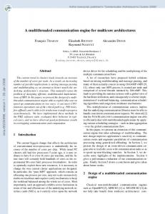
3.3 Automatic Wrapper Generation The overall view of our design environment is shown in Figure 6. An initial internal model is obtained from a translation of the extended SystemC specification, which is a virtual architecture annotated with configuration parameters. There are three tools for automatic wrapper generation: co-simulation wrapper generator, hardware wrapper generator, and the software wrapper generator. Details about these tools can be found in [9][23][24], only their principle will be discussed here. Extended System C
The library used by the hardware wrapper generator [24] has two parts: the processor library and the protocol library. All models stored in this library are synthesizable; they are instantiated and configured using the architecture configuration parameters. The processor library contains processor adapters, template architectures for processors, processor cores, local memories and peripherals. For instance, the following configuration parameters are used for processor adapter instantiation: port addresses, number of interrupts and their priorities. The protocol library contains channel adapters and communication network models. Channel adapter configuration uses the following configuration parameters: input/output type, master/slave operation, type of data transmitted, buffer size, and interrupt parameters.
4. COMPONENT-BASED DESIGN OF A VDSL APPLICATION This section demonstrates the application of the high-level component-based methodology using a VDSL application as a design example.
4.1 The VDSL Modem Specification The design we present in this section was taken from the implementation of a VDSL modem using discrete components [6]; the block diagram for this prototype implementation is shown in Figure 7. The subset we will use in the rest of this paper is shaded in Figure 7. It is composed of two ARM7s and part of the datapath: the TX_Framer, described at the RT-level and was used as a blackbox in this experiment.
Virtual Architecture A
services, and device drivers. Each part contains elements that will be used in a given software layer in the generated OS. This library contains a dependency graph between services/elements that is used to determine the minimal set of elements necessary to implement a given OS service. This mechanism is used to keep the size of the generated OS at a minimum, by avoiding inclusion of unnecessary elements from the library.
C
B
HW w rapper generation
custom O S generation
Co-sim ulation w rapper generation
Host PC
RTL Architecture µP1 A
B
µP2
DSP
C
HW w rapper
HW w rapper
Executable co-sim ulation m odel
C om m unication interconnect
MCU1
The software wrapper generator [9] produces operating systems streamlined and pre-configured for the software module(s) that run(s) on each target processor. It uses an operating system library that is organized in three parts: APIs, communication/system
ARM7 MCU2
Figure 6. Design environment for multicore SoC The co-simulation wrapper generator [23] produces an executable model that is used to validate the internal model. This executable model is composed of a SystemC simulator that acts as a master for other simulators. A variety of simulators can participate in this co-simulation: SystemC, VHDL, Verilog, and Instruction-set simulators. In the co-simulation wrapper library, there are simulation adapters for the different simulators supported. There are also channel adapters that implement all supported communication protocols in different languages.
ARM7
RAM
Analog Front-end
SW w rapper.
Twisted-Pair (copper line)
SW w rapper
BL-M
VDSL Modem Processor
ASIC Digital Front-end
V-M
Constellation Processor
FPGA BL-M: bit-loading memory V-M: variance memory
FPGA VDSL Protocol Processor I-M
ATM Layer
Di-M
I-M: interleaver memory Di-M: de-interleaver memory
: Part redesigned as a multicore SoC
Figure 7. VDSL multicore SoC architecture Despite all simplifications, the design of the selected subset remains quite challenging. In fact, this application uses two processors executing parallel tasks. The control over the three modules of the specification is fully distributed. All three modules act as masters when interacting with their environment. Additionally, the application includes some multipoint communication channels requiring sophisticated OS services.
4.2 VDSL Virtual Architecture Figure 8 shows the virtual architecture model that captures the VDSL specification. Modules VM1 and VM2 correspond to the ARM7s on Figure 7 and module VM3 represents the TX_Framer block (only the interface is known so it is represented as a blackbox). The virtual architecture can be mapped onto different architectures depending on the configuration parameters annotated in modules, ports, and nets. For instance, the three point-to-point connections (VC1, VC2, and VC3) between VM1 and VM2 can be mapped onto a bus or onto a shared memory if the designer changes the configuration parameters placed on these virtual channels and virtual ports. VM1
VM2
M1
T2
VM3 M3
M2 VC1
T4
SAP
VC2 VC3
T8
T5 . . .
. . .
. . .
. . .
. . .
T1
round-robin scheduler (Sched) and resource management services (Sync, IT). The driver layer contains low-level code to access the CAs (e.g. Pipe LReg for the HNDSHK CA), and some low-level kernel routines. The hardware wrapper for processor VM2 includes a timer module because task T5 (see Figure 8) must wait 10ms before starting its execution. A hardware interrupt is generated by the TIMER block, the task can configure this block using the Timer API provided by the service access port SAP (see Figure 8). The custom OS for VM2 provides a more complex API: the Direct API is used to write/read to/from the configuration/status registers inside the TX_Framer block; SHM and GSHM are used to manage shared-memory communication between tasks. Application code and generated OS are compiled and linked together to execute on each ARM7 processor. The HW wrapper can be synthesized using RTL synthesis. Table 1 presents the results regarding the generated OSs. Part of the OS is written in Assembly, it includes some low-level routines (e.g., context switch and processor boot) that are specific to each processor.
T6 P2
T7 T3
T9
Figure 8. VDSL virtual architecture specification
4.3 Results The manual design of a full VDSL modem requires several person-years; the presented subset was estimated as a more than five persons-year effort. When using this high-level componentbased approach, the overall experiment took only one person during four months (not counting the effort to develop library elements and debug design tools). This corresponds to a 15-fold reduction in design effort. Running all wrapper generation tools takes only a few minutes on a Linux PC 500 MHz, most of the time was spent in writing the virtual architecture model with all the necessary configuration parameters. The behavior of each task was described using the SystemC C++ library [25]. Figure 9 shows the RTL architecture model obtained after HW/SW wrapper generation: two ARM7 cores with their local architectures, the TX_Framer block. Each hardware wrapper acts as a communication co-processor for the ARM7, it contains an ARM7 processor adapter that bridges the ARM7 local bus to the communication adapters (CAs). There is a CA for each virtual channel in the virtual architecture specification. For instance, module VM1 reads test vectors from the environment through a simple register using the Pooling CA, and communicates with VM2 through asynchronous FIFOs using 3 HNDSHK CAs (corresponding to virtual channels VC1, VC2, and VC3). Each software wrapper (custom OS) is customized to the set of tasks executed by the processor core. For example, software tasks running on VM1 access the custom OS using an API composed of two functions: Pipe for communication with VM2, and Signal to modify the task scheduling on runtime. The custom OS contains a
Table 1. Results for OS generation OS # of lines # of lines Code size Data size results Assembly (bytes) (bytes) C VM1 968 281 3829 500 VM2 1872 281 6684 1020 Context switch (cycles) 36 Latency for interrupt treatment (cycles) 59(OS) + 28(ARM7) System call latency (cycles) 50 Resume of task execution (cycles) 26 If we compare the numbers presented in Table 1 with configurable commercial embedded OSs, the results are still very good. Generally, the minimum size for commercial OSs is around 4kbytes; but with this size, few of them could provide the required functionality. Performance was also very good: contextswitch takes 36 cycles, latency for hardware interrupts is 59 cycles (plus 4 to 28 cycles needed by the ARM7 to react), latency for system calls is 50 cycles, and task reactivation takes 26 cycles. Table 2 shows the numbers obtained after RTL synthesis of the HW wrappers using a CMOS 0.35µm technology. These results are good because wrappers account for less than 5% of the ARM7s core surface and have a critical path that corresponds to less than 15% of the clock cycle for the 25MHz ARM7 processors used in this case study. Table 2. Results for the hardware wrapper generation HW # of Critical path interfaces Gates delay (ns) VM1 3284 5.95 VM2 3795 6.16 Latency for read operation (clock cycles) Latency for write operation (clock cycles) Number of code lines (RTL VHDL)
Max. freq. (MHz) 168 162 6 2 2168
Custom OS Custom OS
Pipe
Direct
Signal
Sched. Sync. Pipe LReg
SHM
Sched. Direct register
IT
Signal LReg
Pipe
GSHM
Signal
Sync.
Pipe buffer
Pipe LReg
Pipe internal
Timer IT
SHM internal
Semaph internal
Signal internal
Timer LReg
Signal internal
VM1 ARM7 processor core
Memory (RAM/ROM)
RS CK
CK
CS
CK
CS
Memory (RAM/ROM)
RS CK
CK
RS CK
control
address
data
...
control
CK
HW wrapper
CS
ARM7 processor adapter
CK
ctrl
add.
data
Wrapper bus
CK
ctrl
Polling 16 CA
add.
data
ctrl
CK
Polling Polling 1 CA CA
add.
data
ctrl ctrl
CK
add. add.
HNDSHK 3 CA
...
data data
...
ctrl
CK
HNDSHK 1 CA
add.
data
CK
ctrl
HNDSHK 3 comm. adapter
add.
data
ctrl
CK
HNDSHK 1 comm. adapter
add.
data
ctrl
add.
data
ctrl
test vector
CK
address
RS CK
TIMER
ctrl
add.
data
add.
data
Polling comm. adapter
CS
control
data
control
address
data
HW wrapper
CS
ARM7 processor adapter
Wrapper bus
CK
CK
IP (Tx_Framer)
ARM7 local bus
CK RS
address
data
ARM7 local bus
Address decoder
CS
control
address
data
control
data
address
control
data
address
control
data
clock
address
reset
Address decoder
VM3
VM2 ARM7 processor core
FIFO CA
...
Figure 9. Generated multicore SoC architecture
4.4 Evaluation The results extracted from the RTL model show that our approach can generate hardware/software interfaces and operating systems that are as efficient as manually coded/configured ones. Wrappers are build-up from library components so the HW/SW frontier in wrapper implementation can be displaced. This choice is transparent to the final user since everything that implements the interconnect API (hardware interfaces and OS) is generated automatically. Designers do not need to rewrite the application code because the API does not change (only its implementation does). Furthermore, correctness and coherence can be verified inside tools and libraries against the API semantics without having to impose fixed boundaries to the hardware/software frontier (in contrast to standardized interfaces and buses).
5. CONCLUSION This paper presented a high-level component-based methodology and design environment for application-specific multicore SoC architectures. The system specification is a virtual architecture annotated with configuration parameters described in a SystemClike model. Our component-based design environment has automatic wrapper-generation tools able to synthesize hardware interfaces, device drivers, and operating systems that implement a high-level interconnect API. Results show that wrappers generated automatically by these tools have performances close to the commercial/handcrafted equivalents.
6. REFERENCES [1] [2]
[3] [4] [5] [6]
ITRS, available at http://public.itrs.net/ A. Nagari, et al., “A 2.7V 11.8 mW Baseband ADC with 72 dB Dynamic Range for GSM Applications,” 21st Custom Integrated Circuits Conference, San Diego, 1999. http://www.semiconductors.philips.com/platforms/nexperia/ Oka and Suzuoki, “Designing and Programming the Emotion Engine,” IEEE Micro, vol. 19:6, pp. 20-28, Nov/Dec 1999. P. Paulin, F. Karim, and P. Bromley, “Network Processors: A Perspective on Market Requirements,” Proc. of DATE, 2001. M. Diaz-Nava, G.S. Okvist, “The Zipper prototype: A Complete and Flexible VDSL Multi-carrier Solution”, ST Journal special issue xDSL, September 2001.
[7]
D.E. Culler, J. Pal Singh, “Parallel Computer Architecture,” Morgan Kaufmann Publishers, 1999. [8] D.A. Patterson , J.L. Hennessy, “Computer Organization and Design - The Hardware/Software Interface,” Morgan Kaufmann Pub., 1998. [9] L. Gauthier, S. Yoo, and A.A. Jerraya, "Automatic Generation and Targeting of Application Specific Operating Systems and Embedded Systems Software", IEEE TCAD, Vol. 20 Nr. 11, November 2001. [10] K. Keutzer, “A Disciplined Approach to the Development of Platform Architectures,” Synthesis and System Integration of Mixed Technologies, Nara, Japan, October 18 - 19, 2001. [11] R. Ernst, et al., “The COSYMA environment for hardware/software cosynthesis of small embedded systems,” Microprocessors and Microsystems, 1996. [12] F. Balarin, et al., “Hardware-Software Co-design of Embedded Systems: The POLIS approach,” Kluwer Academic Press, 1997. [13] D. Gajski, et al., “SpecC Specification Language and Methodology,” Kluwer Academic Publishers, 2000. [14] Cadence Design Systems, Inc., Virtual Component Co-design: http://www.cadence.com/products/vcc.html [15] K. Keutzer, et al., “System-level design: orthogonalization of concerns and platform-based design,” IEEE TCAD, Dec. 2000. [16] M. Sgroi, et al., “Addressing the System-on-Chip Interconnect Woes Through Communication-Based Design,” Proc. of 38th Design Automation Conference, Las Vegas, June 2001. [17] IBM Inc., Blue Logic Technology, http://www.chips.ibm.com/bluelogic/ [18] Virtual Socket Interface Alliance, http://www.vsi.org. [19] D. Wingard, “MicroNetwork-Based Integration for SOCs,” Proc. of DAC, Las Vegas, June 2001. [20] J. A. J. Leijten et al., “PROPHID : A Heterogeneous Multi-Processor Architecture for Multimedia,” Proc. of ICCD, 1997. [21] Coware Inc., N2C: http://www.coware.com/ [22] W.O. Cesário, et al., “Colif: A design representation for applicationspecific multiprocessor SOCs,” IEEE Design & Test of Computers, Vol.: 18, Issue: 5, pp. 8-20, Sept.-Oct. 2001. [23] S. Yoo, G. Nicolescu, D. Lyonnard, A. Baghdadi, A. A. Jerraya, “A Generic Wrapper Architecture for Multi-Processor SoC Cosimulation and Design,” Int. Symposium on HW/SW Codesign (CODES) 2001. [24] D. Lyonnard, S. Yoo, A. Baghdadi, A. A. Jerraya, “Automatic Generation of Application-Specific Architectures for Heterogeneous Multiprocessor System-on-Chip,” Proc. of DAC, Las Vegas, 2001. [25] OSCI: http://www.systemc.org/