Rudrapatna K. Shyamasundar, Frederic Doucet, Rajesh K. Gupta, and Ingolf. H. Kr üger. Abstract We ...... B. Rajan and R.K. Shyamasundar. Multiclock Esterel: A ...
Compositional Reactive Semantics of SystemC and Verification with RuleBase Rudrapatna K. Shyamasundar, Frederic Doucet, Rajesh K. Gupta, and Ingolf ¨ H. Kruger
Abstract We present a behavioral semantics of SystemC that succinctly captures its reactive features, clock and time references, macro- and micro-time model, and allows the specification of a network of synchronous and asynchronous components communicating through either high-level transactions or low-level signal and event communications. The proposed semantic framework demonstrates the anomalies introduced by the simulation kernel, in spite of the macro- and micro-time scales. The framework further relates the simulation and logical correctness and provides a technique for scaling up the verification while keeping the correctness intact. Furthermore, we translate SystemC components to RuleBase using our semantic characterization that permits testing and verification of heterogenous designs. We illustrate the verification of a Central Locking System (CLS) designed in SystemC.
Keywords: SystemC, semantics, verification, model checking
1
Introduction
System-level modeling using SystemC facilitates the use of various features and concepts such as perfect synchrony, asynchrony, reactive, and time specifications through a C++ class library. SystemC provides a bridge between hardware and software design and thus, provides a unifying framework for hardware/software design. SystemC consists of C++ libraries and a simulation kernel for creating behavioral and register-transfer level (RTL) designs. It provides a common development environment needed to support software engineers working in C/C++, and hardware engineers working in HDLs such as VHDL, Verilog, etc., particularly system-on-a-chip designs. While the simulation behavior of a SystemC description is well understood by engineers, existing frameworks have not catered to a comparative evaluation of simulation and verification particularly to the various perfect-synchrony features as well as macro- and micro-time scales. We also show that the two time scales, while intended to avoid some of the anomalous behaviors possible in perfectly synchronous languages like Esterel, cannot indeed be avoided. In fact, it also throws open the question whether the δ-cycle can indeed be avoided to speed up simulation without foregoing correctness. S. Ramesh and P. Sampath (eds.), Next Generation Design and Verification Methodologies for Distributed Embedded Control Systems, 227–243. c Springer 2007 �
227
228
R.K. Shyamasundar et al.
In this paper, we describe a compositional semantics using the rewrite framework of Esterel. A sound semantic model provides the ability to reason regarding issues with composition of SystemC models without adding global restrictions other than those imposed by SystemC language itself. With the ever increasing of complexity of systems, it is important to exploit the notion of compositionality that is deeply embedded in the rationale of SystemC. A clean separation of process reaction, and computing the next environment provides a basis for simulation and verification without flattening the composed model into a single uniform model. The main contributions of the paper are: 1. a semantic foundation that captures (i) the synchronous and asynchronous process composition, (ii) all levels of abstractions for communications, and (iii) relation between simulation correctness and logical correctness; 2. a way to scale up the verification while ensuring the simulation and logical correctness and equivalence are intact; and 3. an automatic translation to the model checkers for verification of SystemC components, providing a powerful workbench for testing and verification.
2
Overview of SystemC
SystemC is essentially a C++ library that provides macros to model hardware and software systems. The difference between a system-level modeling language rooted in C++ such as SystemC, and C++ itself, is that the system-level modeling macros are used to model a system, but not to implement it. Figure 1 shows an abstract syntax for SystemC, where we consider only the statements specific to modeling with SystemC and not the general statements in the C++ language. A SystemC program is a set of interconnected modules communicating through channels, signals, events, and shared variables. A module is composed of a set of ports, variables, a process and a set of methods. A process is sensitive to a set of events, and optionally can have program module process-decl process-body
:= := := :=
event-comm
:=
signal-comm chan-comm
:= :=
control-flow arithmetic
:= :=
{ modules, channels, signals, events, variables } { ports, variables, process-decl, process-body, methods } * wait(event) | wait(event,time) | wait(time) | wait(event list) notify(event) | notify-delayed(event) | signal.read | signal.write | tlm port->put(value) | tlm port->get(var) | tlm port->method(parameters)
Fig. 1 Simplified abstract syntax for SystemC.
Compositional Reactive Semantics of SystemC and Verification with RuleBase
229
a reset condition. Some of the distinctive characteristics are informally summarized below: – A process is in the ready state when either the SystemC program starts or there is an event that the process is waiting for. A process is in the waiting state when it is waiting for an event. A process is unblocked when it is notified by an event. Events can be notified immediately, or the notification can be delayed until all processes are waiting. – Time is modeled through macro-time in some pre-defined quantifiable unit; a process waits for a given amount of time, expiration of which is notified through an event. – Between processes, the basic communication is by reading and writing signals. During the execution of a SystemC program, all signal values are stable until all processes reach the waiting state. When all processes are waiting, signals are updated with the new values. – Transaction-level communications are through channels, which are accessed using an interface defined by a set of methods. The transaction-level model (TLM) interface can be put and get methods, to connect to channels like FIFO buffers, etc., or a custom set of methods to connect to specific channels. In the body of the methods, communication is done by using the shared variables, events, signals or other channels defined in the channel. When executing a SystemC program, the illusion of concurrency is provided to the user by a simulation kernel implementing a discrete event simulation loop. The simulation loop divides time into macro-time and micro-time, where micro-time is used for creating a partial ordering of the events that can occur in a macro-time unit. Micro-time events are called delta events, processed into the simulation queue, advancing micro-time as needed without advancing macro-time (to simulate synchronous reactions). Micro-time events are not observable in a macro-time scale because they are used only to simulate a synchronous concurrent reaction on a sequential computer. The discrete-event simulation loop is used to compute the next environment which contains the events to which the processes synchronize. The simulation kernel first synchronizes all the processes with immediate events, and then picks one process to react. This reaction loop is repeated until there are no more immediate events and all processes are waiting. Then, the processes are synchronized with micro-time events, followed by a new reaction loop. When there are no more immediate nor micro-time events, the processes are synchronized with the macro-time events, leading to another reaction loop. Note that simulation cannot guarantee correctness due to: 1. the inability of simulation to produce all possible behaviors, and 2. the simulation loop can introduce anomalous behaviors that cannot happen logically. For example, due to the underlying scheduler (as we discuss in Section 4), the simulation kernel can introduce nondeterminism and causality cycles in a design description.
230
3
R.K. Shyamasundar et al.
Semantic Framework
We now define the behavioral semantics of SystemC compositionally to capture all possible behaviors that can be computed by a SystemC program by composing the semantics of its components. First, we divide the observables as controllable variables and environment variables. For a given SystemC module, the controllable variables are output signals, internal variables, output channels, output events, and the program counter for the process. The environment variables are input signals, input events, input channels, and global variables. At any point during the program, there is at most one process that is reacting to the environment. One can locally visualize instants during which reactions occur by observing the state (C++ variables and program counters for each processes) of the program, denoted σ , or the modeling environment (events, channels, signals, processes, etc.), denoted E. An environment only lasts an instant; i.e., it is not persistent like the state and an event occurs only right after the instant it is emitted. For describing, how a statement changes the configurations of the observables, we use E O ,b rewrite rules of the form ( stmt�, σ ) −−−→ ( stmt � �, σ � ) where: E
– stmt is a SystemC program text with the location of the program counter, before the reaction, and stmt � is the program text with the location of the program counter after the transition, – σ and σ � are the states before and after the reaction respectively, – E is the environment while taking the transition, E O is the output emitted during the transition; in general, an environment is a 4-tuple E = E I , E δ , V δ , L� where: • E I is the set of immediate events, • E δ is the set of next delta events, • V δ is the set of next delta updates for variable, • L is a set of pending transactions or pending asynchronous tasks, – b is a Boolean flag indicating if the process completed in the instant or not. Keeping in view the simulation explained above, a SystemC model behaves in an alternating sequence of synchronizations and reactions (→sync →r eact )∗ ), observable as a sequence of environments and states (E 0 σ0 )(E 1 σ1 )(E 2 σ2 ) . . . .
3.1
Reactive Statements
The reactive semantics forms the crux of the simulation. Some of the rules are given Table 1. The wait-syntactic rule defines that a wait statement is syntactically reduced to the sequence of a pause statement followed by a semantic wait statement. The wait argument e is passed verbatim through the reduction. A pause statement pauses a reaction until the next environment – it does not terminate in the current instant and reduces to nothing. The behavior of the semantic wait statement is to wait
Compositional Reactive Semantics of SystemC and Verification with RuleBase
231
Table 1 Semantics of reactive statements.
(wait-2) e ∈ E ∧ ¬reset(Pi ) 1
(wait(e)) − →()
0
(wait-1) e∈ / E ∧ ¬reset(Pi )
E
(wait(e)) − → (wait(e))
(pause)
(wait-syntax-rewrite) (wait(e)) → (pause; wait(e))
→() (pause) −
(event-notify)
0
E
(event-notify-delta)
e,∅,∅,∅�,1
(e.notify()) −−−−−−−→ ( ) E
E
(weak-reset-unblock) r eset (Pi )
∅,e,∅,∅�,1
(e.notify delta()) −−−−−−−→ ( ) E
(signal-read) 1
∅,∅,∅,∅�,1
(wait; Pi ) −−−−−−−→ (body(P)i ) E
(signal-write-1) sv � = v
∅,se ,v/sv ,∅�,1
(s.write(v)) −−−−−−−−−−→ ( ) E
(sequential-composition-1)
E 1 ,E 1δ ,V1δ ,L 1 �,b1
→ ( , σ [sv /v]) (s.read(v), σ ) − E
(signal-write-2) sv = v 1
(s.write(v)) − →() E
(sequential-composition-2)
E 1 ,E 1δ ,V1δ ,L 1 �,b1
(P1 , σ ) −−−−−−−−−−−−→ (P1� , σ � )
(P1 , σ ) −−−−−−−−−−−−→ ( , σ � )
(P1 ; P2 , σ ) −−−−−−−−−−−−→ (P1� ; P2 , σ � ) E
(P1 ; P2 , σ ) −−−−−−−−−−−−→ (P2 , σ � )
E
E 1 ,E 1δ ,V1δ ,L 1 �,b1
E
E 1 ,E 1δ ,V1δ ,L 1 �,b1 E
for an event e to be in the environment. Rule wait-1 defines that when event e is not in the environment and the reset condition specific to the current process (defined in by variable Pi ) is false, the process continues to wait without doing anything. In rule wait-2, when event e is present in the environment and the reset is not asserted, the wait statement terminates and reduces to nothing. The event notification statement immediately emits an event e in the next environment, and terminates. The delayed notification statement emits event e to be in the next delta environment. The processes waiting on these events will unblock in either the synchronization with the next environment and the synchronization with the next delta environment respectively. The weak-reset-unblock rule shows that when a process is waiting for some event and the reset variable is asserted, the process resets to the initial value for its program counter. Now let us look at statements concerned with signal communications. A SystemC signal s is persistent and is associated with a variable sv which holds the data value, and to an event se to notify signal value transitions. For a signal write operation, if the value v being written to a signal is different than the current value, the statement terminates, reduces to nothing, and emits event se in E δ and v/sv in V δ . Otherwise the statement terminates without doing anything. Finally, there are two cases for sequential composition. If statement P1 does not terminate in the current instant, then P2 cannot start. If P1 terminates then P2 starts in the environment in which P1 terminates.
232
R.K. Shyamasundar et al. sL P1
P2
rL kL
Fig. 2 Asynchrony interface. Table 2 Semantics of timed statements.
(wait-timeout)
(wait-event-timeout)
s L Pi (t),∅,∅,L Pi �,0
(wait(t)) − −−−−−−−−−−−−→ (wait (r L Pi )) E
(wait-timeout-event-1) (r L Pi ∈ E) ∧ ¬r eset (Pi ) 1
(wait (r L Pi |e)) − →() E
3.2
s L Pi (t),∅,∅,L Pi �,0
(wait(t, e)) −−−−−−−−−−−−−→ (wait (r L Pi |e)) E
(wait-timeout-event-2) / E) ∧ (e ∈ E) ∧ ¬r eset (Pi ) (r L Pi ∈
k L Pi ,∅,∅,∅�,1
(wait (r L Pi |e)) −−−−−−−−−→ ( ) E
Statements for Time
Wait-timeout statements are used to request a notification at a later macro-time. For this purpose, we shall assume the presence of an asynchronous timer process in the environment as in CRP [2], that can be called from any process in need of setting an alarm. Figure 2 shows the asynchronous gateway interface. The timer is an asynchronous task, which is started and controlled, indirectly, by the process. The timer has the general interface of the asynchronous task which is described as follows. The asynchronous task is started with an event s L, and the completion of the asynchronous task is notified with event r L. Event k L is used to kill an asynchronous task. The set L contains the labels of all the currently active asynchronous tasks. The semantic functions for the timed statements are given in Table 2. The waittimeout statement requests an alarm after t units of time by sending t on signal s L Pi to a timer L Pi in the environment, with, Pi being the label for the current process. The process then proceeds to wait for an event r L Pi which is to be sent by the timer after t time units. A process can also wait for an event e, with a timeout t, as showed in rule wait-event-timeout. If event e occurs before the time out (before receiving event r L Pi ), the process will resume and kill the pending timer by notifying event k L Pi . It is necessary to kill the pending timer so that, after time t the process will not receive any unnecessary timeout event.
3.3
Rules for Parallel Composition
In SystemC, the parallel composition of the processes is defined as each module is instantiated. All modules are to be executed concurrently once the simulation is
Compositional Reactive Semantics of SystemC and Verification with RuleBase
233
Table 3 Semantics of parallel composition.
(sync-imm) ∀i ∈ {1..l} : ∃e ∈ E I : waiting(P i , e)
∀ j ∈ {l + 1..m} : ∀e ∈ E I : ¬waiting(P j , e)
∅,E δ ,V δ ,L�,1
(P1 )...)Pl )Pl+1 )...)Pm ) −−−−−−−−−→ (P1� )...)Pl� )Pl+1 )...)Pm )
E I ,E δ ,V δ ,L� I
(async-react) ∀i ∈ {1...l} : waiting(Pi )
∀ j ∈ {l + 1..m} : r eady(P j )
E x ,E xδ ,Vxδ ,L x �,0
select x ∈ {l + 1..m} : (Px , σ ) −−−−−−−−−−−→ (Px� , σ � ) E
merge( E xδ , E δ �, Vxδ , V δ �, 1)
E x ,E xδ ∪E δ ,Vxδ ∪V δ ,L s ∪L�,1
(P1 )...)Pl )Pl+1 )...)Pm ) −−−−−−−−−−−−−−−−−−−→ (P1� )...)Pl� )Pl+1 )...)Px� )...)Pm )
E I ,E δ ,V δ ,L�
(sync-micro) ∀i ∈ {1..n} : waiting(Pi )
E δ ,∅,∅,L�,1
(P1 )...)Pn , σ ) −−−−−−−−→ (P1 )...)Pn , σ [V δ /V ])
∅,E δ ,V δ ,L� δ
(sync-macro) ∀i ∈ {1..n} : waiting(Pi )
et ,∅,∅,L�,1
et = next time()
(P1 )...)Pn , σ ) −−−−−−−−→ (P1 )...)Pn , σ [V δ /V ])
∅,∅,∅,L�
T
started. The various booking operations for building the environment can be partitioned as: 1. 2. 3. 4.
synchronizing processes with the events in the environment (denoted → I ), reaction of the selected process (denoted →), building next micro-environment (denoted →δ ), and building next macro-environment (denoted →T ).
The complete simulation loop can then be captured as iterative composition of relations given by: ((→ I →)∗ →δ )∗ →T )∗ . The various semantic rules of composition are given in Table 3. Rule sync-imm is defined to unblock all processes that are waiting for events that are in the environment. We use the notation waiting(P, e) to mean that P is waiting on event e, meaning P is of the form wait; P � . In other words, it is a synchronous composition, but only for the wait statements. Rule asynch-react defines the reactivity. A process which is ready, is selected to run until it reaches the next pause. The merge predicate provides a check on whether or not to allow nondeterministic environments in the composition. Nondeterministic environment are possible when two different values can be written to a signal in the same reaction. The merge predicate checks the feasibility of partially ordering the events in the delta cycle. Setting the third parameter to “1” indicates that the partial
234
R.K. Shyamasundar et al.
order has to be consistent. One can allow nondeterministic environment by setting the third parameter to −1. Rule sync-micro defines the synchronization on delta events to build the next micro-environment. The rule proceeds only when there is no immediate events and there exists some delta events. The transition makes the delta events in E δ become the immediate events in the next instant, and updates the state variables. The rule for the synchronization on timed events builds the next environment from time events and advance macro-time. It is effective when all processes are blocked, where there are no immediate event nor delta event. Timed events are posted by wait(time) statements, timers and clocks. For simplicity in this rules, we use next time() to broadly indicate moving to the next time.
3.4
Statements for Transaction-Level Modeling
For transaction-level method calls, we simply inline the body of the method inside the caller module. The put/get transaction-level channels from the SystemC TLM library, when used as a single place buffer in a point-to-point connection, do not cause nondeterministic behaviors. This is because the state changes in the transaction-level buffers are visible immediately for the calling process, but only at the next delta cycle for the other processes. This behavior is useful to avoid the kind of nondeterministic behavior described in Section 4. Furthermore, using these channels in combination with the step scheduler (described in Section 5) enables efficient transaction-level verification. Table 4 lists the semantic rules for the TLM statements. We consider only the rules for communication with single place TLM FIFO buffers. Rule tlm-put writes data on the buffer if the buffer is empty. Otherwise, it waits that the data already on the buffer is read. Rule tlm-get works similarly in the complementary fashion. Note that these rules are to be used only with the step scheduler as their generalization for the full scheduler would significantly complicate the semantics and require extra copies of the variables in the verification environment (see Section 5).
Table 4 Semantics of transaction-level statements. (tlm-put-1) ¬ f ull( f )
∅, f w ,∅,L�,1
(f->put(v), σ ) −−−−−−−−→ ( , σ [v/put(f )]) E
(tlm-get-1) ¬empty(f )
∅, fr ,∅,L�,1
(f->get(v), σ ) −−−−−−−−→ ( , σ [get(f )/v]) E
(tlm-put-2) f ull( f ) 0
(f->put(v)) − → (wait(fr );f->put(v)) E
(tlm-get-2) empty(f ) 0
(f->get(v)) − → (wait( f w );f->get(v)) E
Compositional Reactive Semantics of SystemC and Verification with RuleBase
3.5
235
Computing the Semantics of SystemC Components
We now show how we generate the transition system for a SystemC component by applying the semantic rules. For a process P, the transformation yields the reactive sequences from initial state σ0 to state σn such as: E 0 ,1
E n−1 ,0
E
E
(stmt, σ0 ) −−→ ... −−−−→ (stmtn , σn ) where from a given state, the process will react until the next wait statement (or up until termination). During the reaction, the states in the sequence between σ0 and σn are observable only from within P, and no other process in the environment can observe the intermediate states. Hence, from another SystemC process, only the first and last states of the reaction are observable: E O ,0
(stmt, σ0 ) −−−→ (stmtn , σn ) E
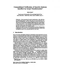
Therefore, when building the transition system for a process, we can reduce a detailed graph to an observable graph with all the intermediate transitions, form an initial state σ0 to a state σn , collapsed to one single transition. From the process description, we use the semantic rules to construct the controlflow graph, and add the predicate for the conditions and assignments. Since we do not keep the state implicitly in the semantic structure, we use the weakest precondition on observable paths to convert the control-flow graph to a graph with only the observable reactive steps. We use the standard definitions for constructively computing weakest precondition. For all the pair of observable points (paths from a pause statement to the next pause statement in the graph) we compute the weakest precondition between the points, and add it to the observable graph if the weakest precondition is satisfiable. Note that one cannot constructively compute the weakest precondition for loops that cannot be unrolled. This is a well known limitation of the approach, but we can alleviate it by requiring wait statements inside loop bodies. Figure 3 shows an example of the semantic translation of a SystemC process. The process is first converted to the control-flow graph, and then to the observable graph. Every transition is labeled with a guard (the conjunction of the labels starting with a G), and the variable assignments should the transition be taken. The process initializes a counter variable to 0, waits on the clock, re-initialize it to 10, and then counts up until it is reset.
4
Anomalous Behaviors
We illustrate various anomalous behaviors such as causality (as in Esterel), nondeterminism, etc.
236
R.K. Shyamasundar et al.
class Module30 : public sc_module { public: Module30(sc_module_name module_name) : sc_module(module_name) , clk() , reset_signal() , counter(0) { SC_CTHREAD(process,clk.pos()); reset_signal_is(reset_signal,true); } SC_HAS_PROCESS(Module30); // Ports sc_in clk; sc_in reset_signal; unsigned int counter;
1 G: !(TRUE) G: TRUE
0 FINAL
6
bflag
_TAU_
5
G: reset_signal__posedge_event?? G: clk__posedge_event?? G: !(reset_signal__posedge_event)
void process() { counter=0; wait(); counter=10; while(1) { wait(); counter++; } } };
7 INIT
9
counter:=0
G: reset_signal__posedge_event??
counter:=(counter)+(1)
8
2
bflag counter:=10
0
3
G: clk__posedge_event?? G: (TRUE)&&(!(reset_signal__posedge_event)) counter:=(counter)+(1)
counter:=0 G: reset_signal__posedge_event??
G: clk__posedge_event?? G: !(reset_signal__posedge_event)
G: clk__posedge_event?? G: (TRUE)&&(!(reset_signal__posedge_event)) counter:=10 counter:=0
2 INIT
4
1
G: reset_signal__posedge_event?? counter:=0
Fig. 3 Example of semantic translation.
4.1
Causality Cycle
A causality cycle is a behavior that triggers an infinite amount of action in a finite amount of time. It is important to look for causality cycles in a SystemC design as causality cycles are not always triggered in simulation. Indeed, a causality cycle can be triggered by a corner case condition in the behavior of the composition of a system of asynchronous components. In a simulation, one can observe a causality cycle when a computation does not stabilize to specific output values in an instant and keeps re-triggering itself. In our semantics rules, a causality cycle occurs when it never gets to the next synchronization with the macro-time events. Indeed, the causal cycle occurs in the reaction (((→ I →)∗ →δ )∗ →T )∗ when step →T is never taken. We now give an example of a SystemC program that has a causality cycle. The component definition for a “watching process” is given in Figure 4(a). The behavior of the watching process is to watch another module, and if the other module has not been triggered, the watching process will trigger it. The component by itself does not
Compositional Reactive Semantics of SystemC and Verification with RuleBase SC_MODULE(WATCH_PROCESS) { sc_in clk; sc_in trigger; sc_in wp_triggered; sc_out trigger_wp; sc_out triggered; SC_CTOR(WATCH_PROCESS) { SC_METHOD(process); sensitive