the homogenization technique used in micro-mechanical models gives good ...... in formed textile compositesâ, Ph. D. Dissertation, Boston University, College.
7th International LS-DYNA Users Conference
Material Technology (1)
COMPUTATIONAL MICRO-MECHANICAL MODEL OF FLEXIBLE WOVEN FABRIC FOR FINITE ELEMENT IMPACT SIMULATION Ala Tabiei∗ and Ivelin Ivanov† The Center of Excellence in DYNA3D Analysis Department of Aerospace Engineering and Engineering Mechanics University of Cincinnati, OH 45221-0070, USA
ABSTRACT This work presents a computational material model of flexible woven fabric for finite element impact analysis and simulation. The model is implemented in the nonlinear dynamic explicit finite element code LSDYNA. The material model derivation utilizes the micro-mechanical approach and the homogenization technique usually used in composite material models. The model accounts for reorientation of the yarns and the fabric architecture. The behavior of the flexible fabric material is achieved by discounting the shear moduli of the material in free state, which allows the simulation of the trellis mechanism before packing the yarns. The material model is implemented into the LSDYNA code as a user defined material subroutine. The developed model and its implementation is validated using an experimental ballistic test on Kevlar woven fabric. The presented validation shows good agreement between the simulation utilizing the present material model and the experiment. Keywords: computational material model, flexible woven fabric, textile composites, and explicit finite element ballistic impact simulation. INTRODUCTION The high modulus fibers such as Kevlar, Spectra, Aramid, Nylon, etc. are vastly used not only in composite materials, but also in netted fabric as structural element which has high strength and flexibility. These two properties are very important for impacted structures, since they allow the structure to withstand large transverse deflection and to absorb the high impact energy. Woven fabrics can be used in structures subjected to transverse loading like human body armors subjected to projectile impact. Another application of the high modulus flexible fabrics is the protective jackets in airplane jet engines. These jackets are placed around the jet engines in order to contain any broken blades from penetrating the engine casing and consequently the fuselage. Modeling of the flexible fabric behavior under membrane and transverse loading is a challenging task. The difficulty comes from the dual behavior of the fabric. In the free state, the fabric material behavior resembles trellis mechanism [1] with big reorientation of the yarns. ∗ †
Assistant Professor and Director, author to whom correspondence should be addressed Graduate Research Assistant
8-15
Material Technology (1)
7th International LS-DYNA Users Conference
Initially, fill and warp yarns are mutually perpendicular (Fig 1,a). The load is carried by the yarns in their axial direction only. In any other in-plane direction they are free to rotate up to some locking angle (Fig. 1,b). The fabric slightly resists shear strain (and yarn rotation) due to the friction between yarns. When the rotated yarns have reached the locking angle between yarns (Fig. 1,c), the area density of the fabric is the highest and the yarns are packed in a block that has anisotropic properties. Moreover, the properties of the packed fabrics are of a general anisotropic material with many inclined principle axes. Some models of the flexible fabric material available in the literature use the pin-joined mechanism of bars. Ting et al. [2] and Shim et al. [3] modeled the fabric material as an orthogonal grid of pin-joined member elements. Contact algorithm and transverse pressure loading are the difficult problems in such models. The finite element mesh has to be in scale of the fabric structure, which presents some difficulties in the general use of such models. The friction and the locking angle constraints are absent in most of these models. Even if they have been introduced in such models, the behavior of the model after locking will not be adequate because of the lack of transverse interaction of the members. Vinson and Zukas [4] and Taylor and Vinson [5] modeled the fabric as conical isotropic shells for ballistic impact analysis. As a result of isotropic material assumption the models are not able to distinguish the membrane directions, and as a result the behavior of the material is the same in all directions, which is not confirmed by experimental results. Johnson et al. [6] tried to amend that by modeling the fabric by both pin-joined members and thin membrane shells. Bilinear stress-strain relationship is assumed for bar elements in order to simulate the dual behavior of the fabric before and after the locking of the trellis mechanism. The shell elements provide the contact surface in this model. The impact and ballistic problems can be simulated successfully by means of non-linear dynamic finite element codes. Such codes are heavily used in many industries as they provide a powerful tool and cost effective process for simulation-based designs. Based on previous developments of woven fabric composite computational models [7,8,9], it was anticipated that the homogenization technique used in micro-mechanical models gives good results with respect to the complex anisotropy modeling of the flexible fabric structures. A micro-mechanical model of the woven fabric can account for the crimping of the fibers. Shell elements are better structural elements for contact problems and transverse pressure loading in the finite element method. Therefore it was decided to develop a model of the flexible woven fabric material, that can simulate a trellis mechanism with reorientation of the yarns and their locking, based on micro-mechanics. The developed computational material model is implemented in the dynamic explicit nonlinear finite element code LSDYNA as a user defined material model that is compatible with membrane shell elements. The model was utilized to solve a ballistic impact problem of woven fabric material. In what follows, a description of the model and its implementation is presented.
THE COMPUTATIONAL MICRO-MECHANICAL MODEL The Representative Volume Cell (RVC) approach is utilized in the micro-mechanical model development. The interlacing yarn pattern of the flexible weave fabric is depicted in Figure 1. As a result of the deformations, the fill and the warp yarns are no longer orthogonal although at the unloaded state, they could be orthogonal (the angle between fill and warp 8-16
7th International LS-DYNA Users Conference
Material Technology (1)
direction is a user input parameter in the formulation). The RVC in this case is a rectangle in the plane of the fabric with diagonals in the fiber directions (Fig. 1,b) rather than a square with midsides in the fiber directions, which is usually used in other models [7,8,9]. The RVC structure is shown in Figure 2. The RVC is divided into four sub-cells, two anti-symmetric sub-cells containing the undulated fill-yarn and two other anti-symmetric subcells containing the warp yarn. The direction of the yarn in each sub-cell is determined by two angles – the braid angle, θ, and the undulation angle of the yarn, which is different for the fill and warp-yarns, βf and βw, respectively. The starting point for the homogenization of the material properties is the determination of the yarn stiffness matrices. The material of the yarn is assumed to be transversely isotropic: 1 E 1 − ν12 E1 ν − 12 [C ′] = [S ′]−1 = E1 0 0 0
ν − 12 E1 1 E2 ν − 23 E2
ν − 12 E1 ν − 23 E2 1 E2
0
0
0
0
0
0
0
0
1 µG12
0
0
0
0
1 µG23
0
0
0
0
0 0 0 0 0 1 µG12
−1
,
(1)
where E1 , E 2 , ν 12 , ν 23 , G12 and G23 are Young’s moduli, Poisson’s ratios, and the shear moduli of the yarn material, respectively. µ is a discount factor, which is function of the braid angle, θ, and has value between µ0 and 1. Initially, in free stress state, the discount factor is a small value (µ0 θ + ∆θ up
(41)
where θ dn = 45° − θ lock is the lowest locking angle, θ up = 45° + θ lock is the highest locking angle, θlock is the range to the locking angles (Figure 4.), and ∆θ is the transition range of the braid angle. The graph of the above function is given in Figure 5. The range to the locking angle, θlock , can be obtained from the yarn width and the spacing parameter of the fabric using simple geometrical relationship [1]. The transition range, ∆θ, can be chosen to be as small as possible, but big enough to prevent high frequency oscillations in transition to compacted state and depends on the range to the locking angle and the dynamics of the simulated problem. The minimal discount factor, µ0, should provide very small shear resistance and negligible tension in the yarns when the tension in bias direction is applied and the yarns are still opened. The best way, of course, these parameters to be chosen is if we have force-displacement curve recorded during the trellis frame tension test of the fabric in 8-23
Material Technology (1)
7th International LS-DYNA Users Conference
bias direction of loading [1]. Then we can choose the parameters to simulate and fit the forcedisplacement curve to the recorded one in the experiment.
NUMERICAL RESULTS
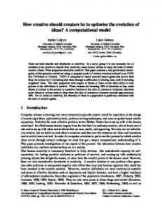
The developed woven flexible fabric material model is programmed as a user defined material subroutine in the LSDYNA finite element software. The implementation in LSDYNA is for balanced woven fabrics. The user defined material model works with reduced and fully integrated membrane shell elements. The capability of the model to simulate the behavior of fabric structures in dynamic problems was examined with simulating a ballistic impact problem. The results of the simulation are compared to the experimental result described in [12]. Ballistic impact of a blunt projectile onto Kevlar® 129 piece of fabric was simulated. The projectile has mass 2.8 g and initial velocity 341 m/s. The projectile is a cylinder with diameter and height of 5.38 mm. The elastic properties of the fabric material are: E1 = 99.1 GPa , E 2 = 7.4 GPa , G12 = 2.5 GPa , G23 = 5.0GPa , ν 12 = 0.2
, ν 23 = 0.2
.
The fabric architecture is β f = β w = 1° , θ lock = 5° , ∆θ = 0.5° and the discount factor is
µ 0 = 1 × 10 −5 . The fabric model has dimensions of 200×200×4.75 mm and was meshed by quad membrane elements. The results of the ballistic impact simulation can be seen in Fig. 6 as sequential images of deflected fabric surface and its profile. The shape of the deflected area is similar to quadratic pyramid, which is confirmed by the experiments [12]. The time history of the projectile displacement (Fig. 7) and the projectile velocity (Fig. 8) almost coincide with those in [12]. The history of the contact force between the projectile and the fabric is given in Fig. 9 and the fully absorbed kinetic energy history is given in Fig. 10. The different reorientation of the yarns in the finite elements depending on their position on the deflected surface is observed in the FE simulation. The difference is in the direction of the braid angle change. As it can be seen in Fig. 11. the yarns in some elements are being opened, while in the others, they are being closed. This demonstrates how the trellis mechanism simulation of the material model works in the ballistic impact FE simulation. In order to demonstrate the behavior of the fabric model further, we simulated airbag inflation of a closed cylinder. The example is a cylinder with conical bottoms suspended on two springs. The orientation of the yarns is in ±45° with respect to the axial direction. The mass flow of the air in the airbag is ramp and the graph of this loading is shown in Fig. 1. The properties of the transversely isotropic yarn material are as follows: E1 = 200 MPa , E2 = 10 MPa , G12 = G23 = 38 MPa , ν12 = ν23 = 0.2 . The angle range to the locking is 20° from the initial position of the yarns and it allows the fabric model to stay open during the simulation. The discount factor of the shear modulus is 1×10⁻⁴. The closed thin cylinders under uniform internal pressure have 2D-stress with a ratio of the hoop stress to the axial stress equals 2:1. This difference drives the yarns of the loosely woven fabric material to get closer in the hoop direction and opener in the axial direction. As a result of the 8-24
7th International LS-DYNA Users Conference
Material Technology (1)
deformation, the airbag shrinks in axial direction and swells in transverse direction. A demonstration of this behavior is depicted by successive states of the simulation in Fig. 2. The axial length change of the airbag is shown in Fig. 3. We can read 34 mm shrinking, which can be considered as significant. The diameter change of the cylinder is shown in Fig. 4. The swelling of the airbag in the transverse direction is approximately 15 mm. The airbag volume change as a result of the dimension change is shown in Fig. 5. The volume change is proportional to the squared diameter change and to the axial length change. The volume change of the airbag influences the pressure in the airbag. The development of the pressure is shown in Fig. 6. This kind of behavior is mainly due to the change of the angle between yarns. The graph of the angle change is shown in Fig. 7. A mutual rotation of 18 degree can be read for the yarns. Suppressing the shear modulus discount and the yarn reorientation tracking in the fabric model, we get a solid material model, which is suitable for tightened woven fabrics. The tightened woven fabrics have very different behavior. The behavior of the tightened woven fabric model is shown in Fig. 8 by the first and the last state of the simulation of inflated airbag. No visual change of the shape can be found. The axial length change is given in Fig. 9 and the diameter change is in Fig. 10. Both show insignificant swelling in all directions. The volume change is shown in Fig. 11 and the pressure change is in Fig. 12.
CONCLUSION
The developed micro-mechanical material model of flexible woven fabric can model the dual behavior corresponding to the real behavior of the fabric material. It can represent the trellis mechanism behavior before the locking of the yarns and the generally anisotropic elastic properties of the fabric material after packing of the yarns. The model can be successfully utilized to represent the behavior of flexible woven fabrics under transverse loading in FE simulation codes. The model shows very good capability for simulating ballistic impact problems and is validated through an experimental test.
ACKNOWLEDGMENT
Computing support was provided by the Ohio Supercomputer Center. Their support is gratefully acknowledged.
8-25
Material Technology (1)
7th International LS-DYNA Users Conference REFERENCES
1. T.M. McBride, “The large deformation behavior of woven fabrics and microstructural evaluation in formed textile composites”, Ph. D. Dissertation, Boston University, College of Engineering, (1997). 2. J. Ting, D. Roylance, C.H. Chi and B. Chitrangad, “Numerical modeling of fabric panel response to ballistic impact”, Proceedings of the 25th International SAMPE Technical Conference, October 26-28, (1993). 3. V.P.W. Shim, V.B.C. Tan and T.E. Tay, “Modeling deformation and damage characteristics of woven fabric under small projectile impact”, International Journal of Impact Engineering, 16, 585-605, (1995). 4. J.R. Vinson and J.A. Zukas, “On the ballistic impact of textile armor”, Journal of Applied mechanics, 6, 263-268, (1975). 5. W.J. Jr. Taylor and J.R. Vinson, “Modeling ballistic impact into flexible materials”, AIAA Journal, 28, 2098-2103, (1990). 6. G.R. Johnson, S.R. Beissel, and P.M. Cunniff, “A computational model for fabric subjected to ballistic impact”, Proceedings of the 18th International symposium on ballistics, San Antonio, TX, November 15-19, (1999). 7. A. Tabiei and Y. Jiang, “Woven fabric composite material model with material nonlinearity for nonlinear finite element simulation”, International Journal of Solids and Structures, 36 (18), 2757-2771, (1999). 8. A. Tabiei, Y. Jiang, and Y. Witao, “Novel micromechanics-based woven fabric composite constitutive model with material nonlinear behavior”, AIAA Jounal, 38 (8), 1437-1443, (2000). 9. R. Tanov and A. Tabiei, "Computationally Efficient Micromechanical Woven Fabric Composite Elastic Constitutive Models", Journal of Applied Mechanic, Vol 68, march 2001. 10. R.D. Cook, D.S. Malkus, and M.E. Plesha, “Concepts and applications of finite element analysis”, New York: Wiley, 3rd edition, (1989). 11. M. Karayaka and P. Kurath, “Deformation and failure behavior of woven composite laminates”, Journal of Engineering Materials and Technology, 116, 222-232, (April 1994). 12. D. Starratt, G. Pageau, R. Vaziri, and A. Poursartip, “An instrumented experimental study of the ballistic impact response of Kevlar® fabric”, Proceedings of the 18th International symposium on ballistics, San Antonio, TX, November 15-19, (1999).
8-26
7th International LS-DYNA Users Conference
Material Technology (1)
o
45
o
45
a) Free state Representative Volume Cell θ
θ
b) Stretched
θmin θmin
c) Compacted Fig. 1. Plain-woven fabric interlacing pattern. z
warp yarn
"W"-sub-cell
y "F"-sub-cell
β θ fill yarn
"f"-sub-cell "w"-sub-cell
x
Fig. 2. Micro-mechanical model.
8-27
7th International LS-DYNA Users Conference
Material Technology (1)
z
1
β
3
2
y
θ
β
θ
x
Fig. 3. Yarn orientation. qf
y fill yarn θ
warp yarn
x θ
RVC
qw θdn o
45
locking area θlock
θlock
θup
Fig. 4. Locking angles.
µ 1
θlock
θlock ∆θ
∆θ
µ0 θdn
o
45
θup
θ
Fig. 5. Discount factor, µ, as a function of braid angle, θ.
8-28
7th International LS-DYNA Users Conference
Material Technology (1)
Fig. 6. Deflection of the fabric surface impacted by a projectile
8-29
Material Technology (1)
7th International LS-DYNA Users Conference
25
Displacement (mm)
20
15
10
Simulation 5
Experiment
0 0
0.05
0.1 Time (ms)
Fig. 7. Projectile displacement
8-30
0.15
0.2
7th International LS-DYNA Users Conference
Material Technology (1)
350
300
Simulation Experiment
250
150
100
50
0 0
0.05
0.1
0.15
0.2
Time (ms)
Fig. 8. Projectile velocity 14
Simulation
12
Experiment 10
8 Force (kN)
Velocity (m/s)
200
6
4
2
0 0
5
10
15
20
25
Displacement (mm)
Fig. 9. Contact force between the projectile and the fabric
8-31
Material Technology (1)
7th International LS-DYNA Users Conference
200
Energy Absorbed (J)
150
100
Simulation
50
Experiment
0 0
5
10
15
Displacement (mm)
Fig. 10. Energy absorbed by the fabric.
8-32
20
25
7th International LS-DYNA Users Conference
Material Technology (1)
Fig. 11. Braid angle change of two different elements and their position on the surface of impacted fabric model.
Fig. 1. Air mass flow as ramp loading.
8-33
Material Technology (1)
7th International LS-DYNA Users Conference
Fig. 2. Successive states of short airbag with loosely woven fabric model inflation simulation.
8-34
7th International LS-DYNA Users Conference
Material Technology (1)
Fig. 3. Axial length change of short airbag with loosely woven fabric model.
Fig. 4. Diameter change of short airbag with loosely woven fabric model.
8-35
Material Technology (1)
7th International LS-DYNA Users Conference
Fig. 5. Volume change of short airbag with loosely woven fabric model.
Fig. 6. Pressure change in short airbag with loosely woven fabric model.
8-36
7th International LS-DYNA Users Conference
Material Technology (1)
Fig. 7. Change of the angle between the yarns for short airbag with loosely woven fabric model.
Fig. 8. Successive states of short airbag with tightened woven fabric model inflation simulation.
8-37
Material Technology (1)
7th International LS-DYNA Users Conference
Fig. 9. Axial length change of short airbag with tightened woven fabric model.
Fig. 10. Diameter change of short airbag with tightened woven fabric model.
8-38
7th International LS-DYNA Users Conference
Material Technology (1)
Fig. 11. Volume change of short airbag with tightened woven fabric model.
Fig. 12. Pressure change in short airbag with tightened woven fabric model.
8-39
Material Technology (1)
8-40
7th International LS-DYNA Users Conference