ISA Transactions®
Volume 45, Number 2, April 2006, pages 249–258
Computer control of a powered two degree freedom reciprocating gait orthosis Bashir M. Y. Nouria,* Arafat Zaidanb,† a
Department of Mechanical Engineering, Faculty of Engineering, An-Najah National University, P.O. Box 7, Nablus, West Bank, Palestine b Department of Mechatronics Engineering, Faculty of Engineering, The Hashemite University, P.O. Box 150459, Zarqa 13115, Jordan
共Received 28 June 2004; accepted 12 October 2005兲
Abstract The design of a motion control system for a powered reciprocating gait orthosis is considered. Models for the orthosis are obtained using least squares identification. The control system design is based on pole-placement techniques and a restricted Youla parametrization of the controller. Experimental results are included. © 2006 ISA—The Instrumentation, Systems, and Automation Society. Keywords: Powered orthosis; Pole-placement controllers; Identification
1. Introduction Many investigations on orthotic devices for paraplegics have been undertaken during the last 25 years. Ferris et al. 关1兴 investigated an anklefoot orthosis powered by artificial pneumatic muscles. Harwin 关2兴 discussed the theoretical considerations for the design of simple teleoperators and powered orthosis. Despite substantial advances, a suitable orthosis that gives paraplegics a minimum ability to walk without strenuous efforts has yet to be developed. The principal disadvantages of current devices are their high complexity and low degree of anthropomorphism. An anthropomorphic orthosis is usually defined as a portable mechanism with a configuration and degrees of mobility that correspond to those of patients body 关3兴. In addition, a walking orthosis should produce locomotion cycles that closely resemble those of a *E-mail address:
[email protected] †
E-mail address:
[email protected]
healthy human being. Such walking patterns can be generated by special computer programs and realized by means of slave drives with the aid of suitable motion control systems. This paper presents a developed motion control systems for a reciprocating gait orthosis 共RGO兲. The hip joints are actuated by electronically commutated direct current 共dc兲 motors 共brushless motors兲. It is worth stressing at this point that it is not our intention or aim to provide all the power required for human mobility, but rather to assist the efforts of the upper body musculature. The patient still contributes some motive effort and maintains balance with the aid of crutches or frames. Adopting this approach has enabled us to minimize the size and weight of the components in the external drive Engineering 关4–6兴. The objectives of this research are: 共1兲 to extend the ambulatory capability of paraplegics beyond that provided by an unpowered orthosis and 共2兲 to improve the dynamical control of the
0019-0578/2006/$ - see front matter © 2006 ISA—The Instrumentation, Systems, and Automation Society.
250
Bashir M. Y. Nouri & Arafat Zaidan / ISA Transactions 45, (2006) 249–258
Fig. 1. Diagram of the powered orthosis.
orthosis beyond the performance that can be achieved by classical proportional integral differential 共PID兲 controllers.
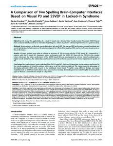
2. System description The device under consideration is based upon conventional RGO, and modified to incorporate two electrical drive units. The device is developed to counteract flaccidity of the lower limbs of paraplegics. The lineage of this form of aid extends at least to the 1960s, with earlier designs in turn being the product of an evolution development originating from the earliest caliper designs. Fig. 1 shows a diagram of the considered powered orthosis with all its components and Fig. 2 presents detailed information of the used mechanics for the actuator drive system of the powered orthosis. The major components of the powered orthosis are numbered such in Fig. 1 and described as the following.
Fig. 2. Mechanics of drive actuator system.
The motor is contained within the cover of the drive unit 共1兲, which is mounted on the sacral band of the orthosis. The motor actuates a lever 共3兲, that is attached to the coupling at the hip joint 共5兲 by means of a ball screw and nut arrangement 共2兲. Each hip joint has a latch plunger. When the plunger is set in its locked position the motor flexes or extends the hip joint, thereby assisting walking. Disengagement of the plunger allows the hip to rotate freely so that the user can sit down whilst still wearing the orthosis. During walking, rotation of the motor and screw are stopped and reversed at each end of the actuator stroke by electronic control. The motor produces a rotational torque, which is converted to a translation force by the ball screw mechanism and that is converted to a rotational motion via a lever attached directly to the hip. The actuators of RGO are electronically commutated brushless dc motors, that have the advantage of small size and high power capability. The used dc motors can deliver up to 100 W peak power with 80% efficiency and more than 0.700 N m peak torque. However, the maximum continuous deliverable power of which 20% should be thermally dissipated 共80% efficiency兲 at room temperature, produces a maximum continuous torque at the motor shaft of 0.152 N m 共 26.3 N m at the hip兲. The estimated continuous torque at the hip 共26.3 N m兲 indicates that a subject of 70 kg mass, 1 m leg, and 0.75 m stride can attain walking speed of about 22 m / min. Since the actuators of the RGO are electronically commutated dc motors, a suitable motor driver 共controller兲 is needed. The motor driver should be able to provide torque and speed in both direction, and a holding torque at zero speed. For that purpose, a four quadrant driver is used; it consists of an analogue proportional-integral controller that has suitable gains. The supply voltage of the controller is in range 12– 50 V dc 共in the laboratory, a 30 V dc and ±6 A is used兲. To make the orthosis fully autonomous, a 24 V NiCad batteries could be used. For the purpose of control, the speed of the dc motors is measured by digital encoders 共500 pulses/rev兲 that are mounted directly at rotor of each motor. The relative angular displacement between the leg and the hip is measured by a potentiometer that is mounted at each hip joint. These
Bashir M. Y. Nouri & Arafat Zaidan / ISA Transactions 45, (2006) 249–258
Fig. 3. Block diagram of experimental setup.
potentiometers are used for controlling the position of the whole orthosis, i.e., to control the size of the stride. 3. System identification The model of the orthosis can be derived by analytical or experimental means. The analytical approach is the only option during the design stage when no prototype has been constructed. It is also useful for the selection of suitable actuators. Experimental methods provide more accurate models, and can be implemented once the system is built. The considered powered orthosis is already designed and constructed; Section 2 presented the description of the orthosis. For this reason, an experimental identification procedure of linear discrete-time models using least squares techniques is carried out. Several experiments are conducted on each driving dc motor for swinging one leg at a time. In these experiments, pseudorandom binary inputs with different amplitudes, and several sampling frequencies are used, and different loading conditions including a person are used. Fig. 3 shows a block diagram of used experimental setup. In order to reduce quantization and aliasing effects, an amplifier and a first order filter are used prior to sampling. The data were processed off-line using Matlab and the System Identification Toolbox. The general form of model to be identified is
A共q−1兲y 共t兲 = B共q−1兲u共t兲 + e共t兲 ,
共1兲
A共q−1兲 = 1 + a1q−1 + ¯ + anaq−na ,
共2兲
B共q−1兲 = b1q−1 + b2q−2 + ¯ + bnbq−nb ,
共3兲
where q is the unit backward shift operator 共unit delay兲, u共t兲 denotes the input voltage to the motor drive, y共t兲 is the output of the antialiasing filter, and e共t兲 represents noise/errors that cannot be measured directly. The unknown parameters are
251
the orders of the polynomials na, nb, time delays and the polynomial coefficients ai, b j. The early experiments indicate that for the sampling time intervals of 10 and 20 ms, the output data are substantially corrupted by noise 共even with the filter兲. Under these conditions it is difficult to obtain consistent results using least squares identification. The source of the noise was largely due to mechanical vibrations in the orthosis. Since the potentiometer measures the relative angle between the hip and leg, it is the most important element in reducing the noise subjected to vibrations in the orthosis. This problem can be solved by increasing the sampling time interval to 40 ms and limiting the maximum amplitude of the motor drive input voltage to 4 V. For this sampling time interval, the usual rule of thumb indicates that a closed loop bandwidth of 1.25– 2.5 Hz can be achieved. For the orthosis it is anticipated that a bandwidth of 0.5 Hz is sufficient. All the experiments show that the identified models have always the same structure, i.e., na = 4, nb = 5 and b1 = 0 共a time delay of 80 ms兲. There are small variations in the numerical values of the polynomial coefficients but all the identified models are stable. A typical model for the considered orthosis is
A共q−1兲 = 1 − 1.7167q−1 + 0.7520q−2 + 0.3061q−3 − 0.3341q−4 ,
共4兲
B共q−1兲 = 0.0743q−2 + 0.0285q−3 + 0.0291q−4 + 0.0432q−5 .
共5兲
The model is stable, has a crossover frequency of about 1.2 Hz, a dc gain of 23.99 and is minimum phase. The model is obtained for a pseudorandom binary input amplitude of 4 V. Fig. 4 shows the experimental output and a simulation of the model using the same input. The model 关Eqs. 共4兲 and 共5兲兴 is crosschecked with other derived models and validated. The model also managed to capture the behavior of the orthosis when it is loaded. That makes the model suitable to be used for designing a suitable controller.
−1
4. Controller design Among the more traditional methods for controller design are PID, lag, lead, and pole-
252
Bashir M. Y. Nouri & Arafat Zaidan / ISA Transactions 45, (2006) 249–258
bances e共t兲. Notice that the integrator is in fact part of the controller as shown in Fig. 5. The closed loop system is given by
y 共t兲 =
F共z−1兲共1 − z−1兲 B共z−1兲H共z−1兲 r共t兲 + e共t兲 , −1 T共z 兲 T共z−1兲 共6兲
u共t兲 =
A共z−1兲H共z−1兲 G共z−1兲 r 共 t 兲 − e共t兲 , T共z−1兲 T共z−1兲
共7兲
where Fig. 4. Experimental and simulated outputs for a pseudorandom binary input 共4 V兲.
T共z−1兲 = A共z−1兲共1 − z−1兲F共z−1兲 + B共z−1兲G共z−1兲 ,
assignment controllers. The pole-assignment method is particularly appealing since the designer can completely specify the closed-loop poles of the system. For any given set of closed loop poles the controller computation is a straightforward task of solving a set of simultaneous linear equations. The main problem in designing a pole placement controller involves the selection of the closed loop poles to achieve good performance and a reasonable degree of robustness. Once a controller has been designed, a family of stabilizing controllers using Youla’s Parametrization can be obtained 关7,8兴. The main advantage of this technique is that it can be applied to any system despite its poles and zeros locations. Moreover, using Youla’s parametrization we have additional degrees of freedom for tuning the controller to improve performance and robustness of the closed loop system. However, the resulting controller will become more complex. The feedback scheme for the model given by Eq. 共1兲 is shown in Fig. 5. The signal r共t兲 denotes the reference or set point for the controller and will be used to specify gait cycles. An integrator was added to the model to ensure zero steady state error for a step input and reject constant distur-
T共z−1兲 = 1 + t1z−1 + ¯ + tntz−nt ,
共9兲
F共z−1兲 = 1 + f 1z−1 + ¯ + f nf z−nf ,
共10兲
G共z−1兲 = g0 + g1z−1 + ¯ + gngz−ng .
共11兲
共8兲
The precompensator H共z−1兲 is chosen as a constant, so that the closed loop system r共t兲 → y共t兲 has unity gain. Since an integrator is included in the controller we have
H = G共z−1兲兩z=1 ,
and hence, H does not depend on the model parameters. We now consider a parametrization of all controllers that will yield the same closed loop polynomial T共z−1兲. This parametrization was essentially introduced by Youla et al. 关9–12兴. Let F0共z−1兲 and G0共z−1兲 be the minimum order controller satisfying Eq. 共8兲. Then any other F and G are given by
F共z−1兲 = F0共z−1兲 + B共z−1兲 P共z−1兲 ,
共13兲
G共z−1兲 = G0共z−1兲 − A共z−1兲共1 − z−1兲 P共z−1兲 . 共14兲 In this work P共z−1兲 is restricted to be a finite polynomial to simplify calculations
P共z−1兲 = p0 + p1z−1 + ¯ + Pnpz−np .
Fig. 5. Pole-assignment controller configuration.
共12兲
共15兲
For such a polynomial the degrees of F and G are increased by the same amount 共np + 1兲. Equations 共13兲 and 共14兲 provide additional freedom to design the controller F and G. Some important questions are asked, such as: How do we select P to achieve good results? Can we choose P to prevent the closed-loop system becoming un-
Bashir M. Y. Nouri & Arafat Zaidan / ISA Transactions 45, (2006) 249–258
253
Fig. 7. Effect of noise on the control signal u共t兲 as the order of the controller is increased. Fig. 6. Closed loop step response for the chosen T共z−1兲.
G0共z−1兲 = 2.1305 − 3.5229z−1 + 1.5714z−2 stable under model mismatch? Can P be chosen to prevent actuator saturation or fast variations in control signals? Can P be chosen to reduce the effect of noise in y and u? What is a suitable order np of P共z−1兲? These issues have been considered in detail by Refs. 关7,13兴. A summary of results and outline of the computational procedure are given listed as follows. Once T is selected, solve Eq. 共8兲 to obtain the minimum order controller polynomials. For a chosen value of np, the computation of P involves minimising the sum of squares of the coefficients of G with respect to pi’s 共this is equivalent to minimising the L2 norm of G兲.
5. Selection of closed loop poles The selection of the polynomial T共z−1兲 is based on several criteria. The location of the roots is chosen so that the closed loop system would have a closed loop bandwidth of about 0.5 Hz and a closed loop step response with no overshoot. The chosen roots for the closed loop polynomial T共z−1兲 are: 0.86, 0.77, −0.5, and 0.6± 0.5j. Fig. 6 shows a Matlab simulation of the closed loop system step response. The next step is to compute the controller polynomials. Solving Eq. 共8兲 for the minimum order controller yields
F0共z−1兲 = 1 + 0.3867z−1 + 0.2368z−2 + 0.1606z−3 + 0.0957z−4 ,
共16兲
+ 0.6743z−3 − 0.7401z−4 .
共17兲
Both have their roots inside the unit circle. The gain and phase margins for this controller are 3.85 at 2.64 Hz, and 47.7 deg at 0.89 Hz, respectively. Selecting np = 7 gives
P共z−1兲 = 2.0353 + 1.9212z−1 + 1.6957z−2 + 1.3980z−3 + 1.0132z−4 + 0.6215z−5 + 0.2911z−6 + 0.0844z−7 .
共18兲
F and G are obtained from Eqs. 共13兲 and 共14兲. The gain and phase margins for this case are 2.09 at 1.43 Hz and 39 deg at 0.63 Hz, respectively. There is a small degradation in relative stability, however, this occurs at lower frequencies where model uncertainty is likely to be small. 5.1. Benefits of the used technique 共a兲 Equation 共7兲 and Fig. 7 show that the used technique has a substantial reduction of high frequency noise contributions in the control signal u共t兲. Fig. 7 shows the effect of noise on the control signal u共t兲 as the order of the controller is increased. Looking at the minimum order controller it is clear that noise is amplified throughout the entire frequency spectrum. On the other hand, the high order controller attenuate noise in the high frequency region. Although the difference between the different order controllers is very small, the results are actually better at low frequency. The
254
Bashir M. Y. Nouri & Arafat Zaidan / ISA Transactions 45, (2006) 249–258
Fig. 9. Effect of noise on the output signal y共t兲.
Fig. 8. Bode plot of the loop gain 兩BG/ AF共1 − z−1兲兩 for different order controllers.
difference is very prominent at high frequency. The general trend is a faster roll of as the order of the controller increased. 共b兲 A substantial reduction of the loop gain in the high frequency region, see Fig. 8. Hence, the control system is more robust with respect to modeling errors in the high frequency band, with the minimum order controller there is attenuation of approximately −20 dB; with the selected controller 共12th order兲 the attenuation reaches −80 dB. 共c兲 When F0 is not stable, the design can yield a stable polynomial F provided that the plant is strongly stabilizable. 共d兲 Since an integrator is used, the dc gain of G remains constant 关see Eq. 共14兲兴. 5.2. Disadvantages of the used technique 共a兲 The dc gain of F increases and in general noise contributions to y can degrade in the low and mid frequency ranges. Adding an integrator to the controller alleviates this problem in the low frequencies but some degradation still occurs in the mid frequency band, see Eq. 共6兲 and Fig. 9. Fig. 9 shows the effect of noise on the output signal y共t兲. As we have mentioned previously, we
sometimes work in control on the basis of trade off. That is the choice of T共z−1兲 could be to have noise rejection or optimal performance. Fig. 9 shows clearly that as the controller’s order increases, the noise has more effect on the output signal. This is more prominent in the middle frequency range and not so obvious at high frequency. This degradation is not uniform over all frequency ranges. In the middle frequencies range, the high order controllers seem to be better. At high frequency, there is no real difference between them. It is worth noting that the Matlab analysis is done for sine waves having uniform amplitude of 1 V. It is unrealistic to assume that the system will contain noise levels of this amplitude, for example quantization noise may have amplitude of 5 mV. 共b兲 The gain and phase margins can reduce, however, this degradation is again at lower frequencies where the models are more accurate. Fig. 10 shows a clear degradation in relative stability between the minimum order and the 12th order controllers. Taking these figures at face value seems to indicate that these results contradict our statement that “relative stability is improved as the order of the controller is increased.” Fig. 11 shows in more detail the frequency range where the degradation occurs. The figure shows that the degradation occurs in the middle frequency region. Improvements in relative stability occur in the frequency region beyond 2 Hz. A judicious selection for np can be made considering the above issues.
Bashir M. Y. Nouri & Arafat Zaidan / ISA Transactions 45, (2006) 249–258
255
Fig. 10. Nyquist plot of the loop gain for different order controllers.
6. Experimental behavior of different order controllers Figs. 12–15 show a comparison of different order controllers for the same reference signal. Looking at Fig. 12 for the minimum order it can be seen that the orthosis follows the general shape of the reference signal closely, but problems occur when the orthosis is attempting to hold a certain position. That is the transition from one position to another is done perfectly but when holding is required, the orthosis seems to be staggering all the time, resulting in small deviations 共oscillation兲 from the reference signal. As the order of the controller is increased 共see Figs. 13–15兲, there is an improvement from the minimum order in terms of holding. However, the orthosis seems to overshoot at some point, tries to correct but over corrects resulting in slight movement when it is supposed to hold. Fig. 15 clearly shows that the orthosis
Fig. 11. Comparison of relative stability for minimum order and 12th order controller.
Fig. 12. Performance of minimum order controller 共4th order兲. 共a兲 Desired 共dashed line兲 and measured 共solid line兲 hip angular position. 共b兲 Control effort of the 4th order controller.
follows the reference signal very closely and is also capable of holding, only at one instant it overshoots but quickly corrects and holds. Another comparison is the control effort for different order controllers. These are also shown in Figs. 12–15. The control effort for the minimum order controller has clearly more variations than any of the others. That is the controller has to send a signal very quickly all the time to maintain the preset trajectory. In terms of amplitude the different order controllers do not show very different behavior 共approximate peaks of 1.5 V兲. The control effort intensity decreases as the order of the controller is increased. The control effort for the selected controller is much smoother than any of the others.
256
Bashir M. Y. Nouri & Arafat Zaidan / ISA Transactions 45, (2006) 249–258
Fig. 13. Performance of 7th order controller. 共a兲 Desired 共dashed line兲 and measured 共solid line兲 hip angular position. 共b兲 Control effort of the 7th order controller.
Fig. 14. Performance of 9th order controller. 共a兲 Desired 共dashed line兲 and measured 共solid line兲 hip angular position. 共b兲 Control effort of the 9th order controller.
7. Experimental results
be seen that during the transition cycle of the gait there is a slight hesitancy in the orthosis movement. Holding position was also slightly difficult. This is shown in the figures by the ragged peaks of the response rather than a smooth peak. Several problems were encountered:
Most volunteers did not report any discomfort during the experiments to gather data for identification. For walking, training volunteers took approximately 45 min. The subjects were required to take their body weight from the moving leg to the stance leg. Then they were asked to hold that position while the orthosis was swinging the leg forward. Then the subjects were requested to transfer their body weight to the other leg allowing the stance leg to move forward. This procedure was repeated continuously. All the tests were carried out on a flat and smooth level surface 共in door兲. Fig. 16 shows a typical response of the left and right legs. The results indicate that the orthosis followed the preset reference signal closely. It can
共1兲 The subjects were “fighting” the motion especially during the initial transient. This is largely due to the fact that the volunteers did not have any disabilities. 共2兲 None of the volunteers felt comfortable standing on one leg while the swing leg was brought forward. 共3兲 The completion of the gait cycle can fail when the foot of the swing leg is dragged across the floor. This depends on the
Bashir M. Y. Nouri & Arafat Zaidan / ISA Transactions 45, (2006) 249–258
Fig. 15. Performance of 12th order controller. 共a兲 Desired 共dashed line兲 and measured 共solid line兲 hip angular position. 共b兲 Control effort of the 12th order controller.
amount of floor friction but we can forsee that this poses a serious problem for walking on irregular terrain and even level surfaces with carpets.
8. Conclusions The performance of the control system was encouraging and the feasibility of the design technique has been validated. The technique of system identification and controller parameters computation can be implemented entirely on-line as an adaptive controller 关14兴. This is an area for future work and would take into account effects of component variations, e.g., differences in leg inertia, and friction.
257
Fig. 16. Gait orthosis experimental response under load. 共a兲 Left leg response. 共b兲 Right leg response.
To overcome some of the problems encountered during the experimental trials it is important to reduce as much as possible mechanical vibrations in the orthosis. Having a powered knee joint would avoid dragging the foot of the swing leg across the walking surface 关15兴. The existing orthosis has an unlockable knee joint but it is a passive joint. The estimated hip accelerations to unlock this joint are rather high and might not be realistic to use in experimental trials with volunteers or patients. References 关1兴 Ferris, D. P., Czerniechi, J. M., and Hannaford, B., An ankle-foot orthosis powered by pneumatic muscles. Journal of Applied Biomechanics 21, 189–197 共2005兲. 关2兴 Harwin, W., Theoretical considerations for the design of simple teleoperators and powered orthosis. Pro-
258
关3兴 关4兴 关5兴
关6兴
关7兴 关8兴
关9兴
关10兴
关11兴
关12兴
Bashir M. Y. Nouri & Arafat Zaidan / ISA Transactions 45, (2006) 249–258
ceedings of the International Conference on Rehabilitation Robotics (ICORR97), 1997, pp. 47–51. Vukobratovich, M. and Roboty, S., Anthropomorphous Mechanisms. Mir Press, Moscow, 1976. Edwards, J. and Gray, J. O., Powered Hip Orthosis. UK Patent application, No. 9314825 共1993兲. Downes, C. G., Hill, S. L., and Gray, J. O., Control aspects of a powered hip orthosis. Proceedings of 13th IASTED International Conference: Modeling, Identification, and Control, 1994a, pp. 31–34. Downes, C. G., Hill, S. L., and Gray, J. O., Distributed control of an electrically powered hip orthosis. Proceedings of International Conference on Control, 1994b, Vol. 1, pp. 24–30. Mustafa, M. M., Pole-assignment high order controllers and applications to adaptive control with on-line supervision. Ph.D. thesis, Salford University, 1989a. Mustafa, M. M. and Medrano-Cerda, G. A., On the use of high order controllers to improve the robustness and performance of pole-assignment controllers. Proceedings of 28th IEEE Conference On Decision and Control, 1989b, Tampa, pp. 1234–1235. Youla, D. C., Bongiorno, Jr., J. J., and Lu, C. N., Single loop feedback stabilization of linear multivariable dynamical plants. Automatica 10, 159–173 共1974兲. Youla, D. C., Bongiorno, Jr., J. J., and Jabr, H. A., Modern wiener-hopf design of optimal controllers, Part I: The single-input single-output case. IEEE Trans. Autom. Control AC-21 共1兲, 3–13 共1976a兲. Youla, D. C., Jabr, H. A., and Bongiorno, Jr., J. J., Modern wiener-hopf design of optimal controllers, Part II: Multivariable Case. IEEE Trans. Autom. Control AC-21 共3兲, 319–338 共1976b兲. Youla, D. C. and Bongiorno, Jr., J. J., A Feedback
theory of two-degree of freedom optimal wiener-hopf design. IEEE Trans. Autom. Control AC-30 共7兲, 652– 665 共1985兲. 关13兴 Zarrop, B. and Fisher, M., Reduced variance poleassignment self-tuning regulation. Int. J. Control 42 共5兲, 1013–1033 共1985兲. 关14兴 Blaya, J. A. and Herr, H., Adaptive control of a variable-impedance ankle-foot orthosis to assist dropfoot gait. IEEE Trans. Neural Syst. Rehabil. Eng. 12, 24–31 共2004兲. 关15兴 Andersen, J. B. and Sinkjaer, T., Mobile ankle and knee perturbator. IEEE Trans. Biomed. Eng. 50, 1208–1211 共2003兲. Bashir M. Y. Nouri is an Assistant Professor at the Department of Mechanical Engineering at AnNajah National University, Nablus, West Bank, Palestine. He received his bachelor degree in mechanical engineering from Birzeit University, Palestine, in 1994, his Master degree in water resources engineering from K. U. Leuven and V. U. Brussels, Belgium, in 1997, and his Ph.D. in mechatronics engineering from K.U. Leuven, Belgium, in 2001. His interests include: identification, modeling, and simulation of mechatronic systems; control of industrial mechatronic systems including robot control, classical control, and intelligent control; hydraulic and pneumatic systems; transducers, smart materials, and smart structures; microcomputers, interfacing, and data acquisition systems. He is a member of the Jordanian-Palestinian Engineers Association.