Contract. ISTAR*. ADC*. Figure 2: Spectrum of Configuration Management
Concepts ..... CM systems when they install their different CASE tools. provide
more ...
Concepts in Configuration Management Systems Susan Dart Software Engineering Institute Carnegie-Mellon University Pittsburgh, PA. 15123-3890 USA
[email protected] Sponsored by the U.S. Department of Defense
Abstract: There has been considerable progress concerning support for software configuration management (CM) in environments and tools. This paper’s intent is to highlight the user concepts provided by existing CM systems. These are shown as a spectrum. In the spectrum, concepts are seen as extensions to, or generalizations of, other concepts. There is difficulty associated with extracting concepts from CM systems since there is no commonality in terminology concerning CM functionality throughout the software engineering community and many CM systems implement variations on concepts. As a result, each concept presented is described as it exists in one particular CM system. A part of highlighting the concepts involves discussing the scope of issues important to users of CM systems. No single CM system provides all the functionality required by the different kinds of users of CM systems. Rather, each CM system addresses some part of the spectrum of concepts. To complete the report, the CM capabilities of the systems used as examples are briefly described.
1 Introduction It becomes evident upon surveying existing configuration management (CM) systems that there has been progress concerning support for software CM in environments and tools. This is evident from the spectrum of concepts provided by CM systems. The intention of this paper is to highlight that spectrum. To begin, a broadened definition of CM and a CM system are given along with a typical CM scenario.
1.1 Definition of Configuration Management Software CM is a discipline for controlling the evolution of software systems. Classic discussions about CM are given in texts such as [3] and [4]. A standard definition taken from IEEE standard 729-1983 [16] highlights the following operational aspects of CM: • Identification: an identification scheme reflects the structure of the product, identifies components and their type, making them unique and accessible in some form. • Control: controlling the release of a product and changes to it throughout the lifecycle by having controls in place that ensure consistent software via the creation of a baseline product. • Status Accounting: recording and reporting the status of components and change requests, and gathering vital statistics about components in the product. • Audit and review: validating the completeness of a product and maintaining consistency among the components by ensuring that the product is a well-defined collection of components. The definition includes terminology such as configuration item, baseline, release and version. Most CM systems incorporate functionality of varying degrees to support these aspects. And some CM systems provide functionality that goes beyond the above definition. This is due (amongst other reasons) to the recognition of different user roles (discussed further in sections 1.3 and 2.1), disparate operating environments such as heterogeneous platforms, and programming-in-the-large support such as enabling teams of software engineers to work on large projects in a harmonious manner. To capture this extra functionality, it is
worthwhile to broaden the definition of CM to include: • Manufacture: managing the construction and building of the product in an optimal manner. • Process management: ensuring the carrying out of the organization’s procedures, policies and lifecycle model. • Team work: controlling the work and interactions between multiple users on a product. In sum, the CM capabilities provided by existing systems encompass identification, control, status accounting, audit and review, manufacture, process management and team work.
who is in charge of a software group, a configuration manager who is in charge of the CM procedures and policies, the software engineers who are responsible for developing and maintaining the software product, the tester who validates the correctness of the product, the quality assurance (QA) manager who ensures the high quality of the product, and the customer who uses the product. Each role comes with its own goals and tasks. For the project manager, the goal is to ensure that the product is developed within a certain time frame. Hence, the manager monitors the progress of development and recognizes and reacts to problems. This is done by generating and analyzing reports about the status of the software system and by performing reviews on the system.
1.2 The Definition of a CM System As to what constitutes a CM system, there is no universally accepted definition. That is, there is no unified notion of a CM system. For instance, if a system has version control, is it a CM system? Ideally speaking, a CM system is one that provides all functionality based on the definition given above. But practically speaking, any system that provides some form of version control, configuration identification, system structuring, system modelling, and has the intent of providing CM (to some degree) is considered by the software engineering (and sales) community to be a CM system. It should be noted that existing CM systems provide their own combination of functionality rather than a standard set. This report mentions 15 CM systems, yet there are at least 40 CM systems that can be acquired for use today. It is worthwhile clarifying one minor notion for this paper, the notion of a CM system and a CM tool. A CM system can be considered part of an environment where the CM support is an integral part of the environment and the CM system is sold in that manner as part of a package. For instance, the Rational [14] environment has CM functionality that is an integral part of it. A CM tool can be considered a stand-alone tool. For instance, the Revision Control System(RCS) [15]) is a CM tool since it is intended to be installed into an existing environment. But because the distinction is not important to this paper, the term CM system will be used to represent both notions.
1.3 A Typical CM User Scenario Before discussing CM systems, a simple, typical, CM user scenario of an organization is described in order to present a frame of reference. The scenario involves various people with different responsibilities: a project manager
The goals of the configuration manager are to ensure that procedures and policies for creating, changing, and testing of code are followed, as well as to make information about the project accessible. To implement techniques for maintaining control over code changes, this manager introduces mechanisms for making official requests for changes, for evaluating changes (via a Change Control Board (CCB) that is responsible for approving changes to the software system), and for authorizing changes. The manager creates and disseminates task lists for the engineers and basically creates the project context. Also, the manager collects statistics about components in the software system, such as information determining which components in the system are problematic. For the software engineers, the goal is to work effectively in creating the product. This means engineers do not unnecessarily interfere with each other in the creation and testing of code and in the production of supporting documents. But, at the same time, they communicate and coordinate efficiently. They use tools that help build a consistent software product and they communicate and coordinate by notifying one another about tasks required and tasks completed. Changes are propagated across each other’s work by merging them and resolving and conflicts. A history is kept of the evolution of all components in the product along with a log with reasons for changes and a record of what actually changed. The engineers have their own work area for creating, changing, testing, and integrating code. At a certain point, the code is made into a baseline from which further development continues and from which parallel development for variants of other target machines emerges.
The tester’s goal is to make sure all the product is tested and found satisfactory. This involves testing a particular version of the product and keeping a record of which tests apply to which version of the product along with the results of the tests. Any errors are reported back to the appropriate people and fixes are put through regression testing. The QA manager’s goal is to ensure the high quality of the product. This means that certain procedures and policies must be fulfilled with the appropriate approval. Bugs must be fixed and fixes propagated to the appropriate variants of the product with the correct amount of testing applied to each variant. Customer complaints about the product must be followed up. The customers use the product — most likely, different customers use different versions and variants of it. Customers follow certain procedures for requesting changes and for indicating bugs and improvements for the product. Ideally, a CM system suited to this scenario should support all these goals, roles and tasks. That implies, these roles, tasks and goals determine the functionality required of a CM system. This paper presents some concepts that attempt to address these.
1.4 Organization of This Paper The introduction has given a definition of CM and a CM system and an example of a typical CM scenario, thereby hinting at requirements for CM systems. Section 2 describes the scope of CM issues important for users of a CM system. These issues affect users’ expectations for a CM system. Section 3 illustrates the spectrum of CM concepts. Section 4 makes some observations about the future of CM systems, and Section 5 gives a conclusion. The appendix presents an overview of the CM systems referenced in this paper.
• User roles: there are different kinds of users of CM systems and, consequently, different functionality requirements for CM systems. • Integration: the various kinds of integration affect the usability (or "power") of the CM system. • When to start using CM: the point at which a project group may start using a CM system depends on the capabilities of the CM system. • Control Level: a CM system can impose different levels of control over the product and its management. • Process and product: an ideal CM system provides for the CM process as well as for the product and its artifacts. • Automation level: fulfilling CM functions is generally a combination of using both manual and automated procedures. • Functionality: CM systems have features that implement a spectrum of CM functionality. These are discussed below in further detail.
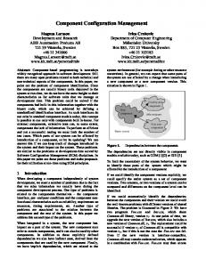
2.1 User Roles As indicated by the scenario of Section 1.3, there are different kinds of users of CM systems.1 Each of these users has a specific role and can have a different view of CM and, hence, different requirements for a CM system. These requirements are distinct and generally complementary. Figure 1 highlights a set of functionality that project managers, configuration managers, software engineers, testers, QA managers and customers expect of a CM system. Each box in Figure 1 represents a major functionality area. The topology of Figure 1 is intended to indicate that the outside boxes (auditing, accounting, controlling, components, structure and construction) are functionality areas that could exist by themselves in any CM system, but when combined with team and process functionality, a holistic (or comprehensive) CM system results.
2 Issues for Users of CM Systems Many issues related to CM affect the user of a CM system. Existing CM systems address these issues in a variety of ways. Although the intent of this paper is to discuss some of the features in existing CM systems, it is worthwhile presenting the issues because all affect the user’s expectations for a CM system. The issues are: 1 There are other kinds of roles pertinent to CM systems: the environment/tool builder and the environment/tool integrator. These roles are not strictly user roles in the sense that this paper presents. They are really related to developing a CM system for the above kinds of users.
CONSTRUCTION
Building Snapshots Optimization Change impact analysis Regeneration
STRUCTURE
TEAM
System model Interfaces Relationships Selection Consistency
Workspaces Conflict resolution Families
AUDITING
Versions Configurations Versions of configurations Baselines Project contexts Repository Kinds of components
History Traceability Logging Lifecycle Support Task Management Communication Documentation
Statistics Status Reports PROCESS
ACCOUNTING
COMPONENTS
Access control Change requests Bug tracking Change propagation Partitioning
CONTROLLING
Figure 1: CM Functionality Requirements
The functionality areas are: • Components: identifies, classifies, stores and accesses the components that make up the product. • Structure: represents the architecture of the product. • Construction: supports the construction of the product and its artifacts. • Auditing: keeps an audit trail of the product and its process. • Accounting: gathers statistics about the product and the process. • Controlling: controls how and when changes are made. • Process: supports the management of how the product evolves. • Team: enables a project team to develop and maintain a family of products. The requirements for these areas are discussed in further detail.
For components’ requirements, users need to: record versions of components, their differences, and reasons for those differences; identify a group of components that make up a configuration and versions of those; denote baselines for a product and extensions to those; identify project contexts that represent the collection of components and artifacts related to a particular project. Furthermore, users need repositories or libraries to store and capture components and CM information as well as the different kinds of components such as source and object code, executables, diagrams, documentation and baselines. For structure requirements, users need to: model the structure of the product via a system model that represents the inventory of components for that product; specify interfaces among components, versions, and configurations, thereby making them reusable; identify and maintain relationships between components; and select compatible components to be made into a valid and consistent version of the product. For construction requirements, users need: means to eas-
ily construct or build the product; the ability to take a snapshot or freeze the status of the product at any time; mechanisms for optimizing efforts at constructing systems by reducing the need to recompile components and saving space; facilities for doing change impact analysis that predict all ramifications of making a change; and easy regeneration of any phase or part of the product at any point in time. For auditing requirements, users require: a history of all changes; traceability between all related components in the product and their evolution; and a log of all the details of work done. For accounting requirements, users need: a mechanism to record statistics, to examine the status of a product, and to easily generate reports about all aspects of the product and process. For controlling requirements, users need: cautious access to components in the system to avoid any unwarranted changes or change conflicts; on-line support for change request forms and problem reports; means for tracking bugs and how, when, and by whom they are dealt with; propagation of changes, in a controlled manner, across different, but related, versions of the product; and a way of partitioning the product for limiting the effects of changes to it. For process requirements, users need: support for their lifecycle model and their organization’s policies; the ability to identify tasks to be done and how and when they are completed; the ability to communicate information to appropriate people about relevant events; and the facilities for documenting knowledge about the product. For team requirements, users need: individual and group workspaces; the resolution of conflicts when merging changes; and facilities for supporting the creation and maintenance of a family of products. Note that the process box and team box are presented as being the significant areas of functionality. This is because they affect, and are affected by, all the other areas. For a user, an ideal CM system would support all the areas of functionality with team and process support fully integrated. No single, existing system provides all the functionality for the areas.
2.2 Integration of a CM System Any CM system has some notion of integration level with its environment. A CM system can co-exist with other tools or be fully integrated. Integration pertains to various aspects of the environment: process, toolset, and database. Process integration means incorporating the usage pattern of the CM system (which makes up the CM process) with the usage pattern of the environment (which pertains to the software lifecycle process). Toolset integration means installing the CM system into the environment so that it can at least co-exist with all the other tools in that environment. For instance, the user would like to invoke CM functions to create a new version every time the "save" command is issued while in the editor. Database integration concerns the (logical) positioning of the CM database — whether it is combined in some way with the extant environment’s database, or whether its database is a separate entity, and whether it makes use of information in other databases. All these kinds of integration are general tool integration and technology transition issues. But since CM is intended to affect most objects in an environment and throughout all phases of the lifecycle of an object, integration of a CM system is bound to have significant impacts on many of the tools in the environment. Most CM systems co-exist with the other tools, and some environments have CM as an inherent part of themselves.
2.3 When to Start Using a CM System It varies as to when project teams start using a CM system on the products they are developing and maintaining. Some teams choose to do so when the product has been through its development lifecycle and is ready for shipment to the customer site. On the other hand, others choose to put everything under CM from the initiation of a project. Both choices have their own overheads. For instance, a team may make the choice based on the overheads associated with asking for a change. That is, if there are a number of manual procedures (such as filing a change request form, seeking CCB approval and getting acknowledgment), a team opts for placing the software under CM control once the major part of development is complete. But if the change request procedure can be done on-line with little time and effort expended by the team, CM will be used at an earlier part of the lifecycle. In theory, CM is applicable throughout the product’s lifetime—from creation, development, product release, customer delivery, customer use, through maintenance. Ideally, CM systems should support this with minimum overhead possible, thereby allowing CM to be applied as early as possible on a project. Existing
CM systems, however, tend to focus mostly on a particular phase of the lifecycle, so users are limited by that functionality.
2.4 Levels of CM Control A number of procedures, policies and tools combine to assist in carrying out CM. They will provide varying degrees of control over the users and evolution of the product. For instance, they may require an engineer to submit a formal, written change request. This is followed by a CCB evaluation and authorization of a change. The configuration manager then sets up a workplace for the software engineer. Particular files are extracted by the configuration manager from a guarded repository and placed in that workspace solely for that engineer. On the other hand, different procedures, policies and tools may actually allow the engineers to electronically mail their request for changes to the configuration manager and other members of the CCB. The members mail their responses immediately. Upon approval, the change request is assigned to an engineer who extracts the pertinent files directly from a repository and makes the changes. All this is done without any manual intervention. And since the CM system would automatically log all accesses, an official record of the change process is created. The first scenario can be considered to have tight, active control over any action, but the latter scenario has loose, passive control over actions. Frequent changes are discouraged in the first scenario because of all the manual overhead, whereas in the latter scenario frequent change is encouraged since it is easy to do. These different levels of control may be more appropriate at certain phases of the product’s lifecycle, for example, the first one is suitable for maintenance but the second for development. Whatever CM system is used, it will have a certain level of control over the user and the timeliness of the product’s evolution. It will either drive the user’s process, enforce it, or a bit of both. Existing CM systems provide their own level of control which is either loose or tight and few are flexible enough to allow the user to pick the kind of control.
2.5 Distinguishing Between Process and Product CM involves a process and a product. A CM process represents the sequence of tasks needed to carry out CM. Essentially, the process is a plan that defines what needs to be done, who does it and how it is be carried out. Supporting the process is a management function. The process model takes into account policies and procedures of the
organization and its software development lifecycle model. The CM product is the result of the process that is an engineering task. A CM system needs to provide functionality for both aspects. Existing systems provide some product and process support, but generally not comprehensive support for both in the same CM system.
2.6 Amount of CM Automation At present, CM is generally a combination of manual and automated procedures. It is possible to perform CM without any kind of on-line assistance. But that is recognized as being inefficient. The goal is to automate as many as possible of the non-creative parts of CM. For instance, written change request forms and the protocol of responding to them are generally documented in an organization’s policy folder rather than captured and enforced on-line. Yet there are systems that can provide for completely automated change requests. Each CM system automates some function of CM to a different degree. And users need to supplement automated procedures with manual ones when procedures are not supported on-line.
2.7 CM System Functionality Existing CM systems provide some of the required functionality for CM, but no single system provides all the functionality required by all the kinds of users. This is likely to improve though, with time, as the needs of users and the capabilities of environment architectures are better understood. The next section highlights the spectrum of concepts in existing CM systems.
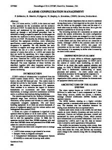
3 Spectrum of Concepts in CM Systems The previous section explained the breadth of issues concerning requirements for CM systems. This section gives details about specific functionality in CM systems. In particular, it examines concepts that support some of the functionality areas identified in the previous section. The concepts are organized as a spectrum to represent an evolution of CM support. Each concept is described as it exists in a particular CM system. The functionality areas of interest for the CM system concepts to be discussed are: component, process, a combination of structure and construction features, and team concepts. Figure 2 shows the entire spectrum of concepts along with their representative CM systems. The following gives a simplified description of each concept and highlights the advantages of the concept. This section ends with a summary of, and an analysis of, the strengths and limitations of the spectrum and the concepts.
Legend:
Concept
Direction of evolutiion
Example system
Context Context management management Lifecycle Lifecycle model model CCC*
Transaction NSE*
PowerFrame* Distributed component
Transparent view SMS*
Sherpa DMS* Change Change request request LIFESPAN* LIFESPAN*
Workspace shape* Object pool
System modelling
Repository Repository RCS* RCS*
DSEE*
Jasmine* Attribution Adele*
Contract Contract
Change set ISTAR* ISTAR*
Consistency maintenance
Subsystem ADC* ADC*
Rational*
CMA*
* This system exemplifies the concept shown in the node
Figure 2: Spectrum of Configuration Management Concepts
3.1 Caveats
3.2 Component Concepts
It should be noted that the concepts and systems discussed are meant to be representative of what exists, rather than a complete summary or evaluation of what exists. For each concept, one CM system is used to discuss that concept. It should be noted though, that some of the CM systems actually provide many of the concepts shown in the spectrum. Concepts are taken directly from specific CM systems since there is no common terminology when dealing with automated CM functionality — each CM system has its own concepts and semantics. The description of concepts is simplified in order to focus on a certain aspect. As a result, it is realized that this may not highlight the full capabilities of concepts (nor of their systems). But, for the sake of presenting a spectrum and in order to hone in on a basic set of CM concepts, simplification is required. Brief overviews of each CM system referenced in this paper are presented in the appendix. The overviews give a more comprehensive listing of the full CM capabilities of each system.
Component concepts deal with identifying and accessing components of a software product. They are the repository and distributed component and are described below. 3.2.1 Repository The notion of a repository is fundamental to a CM system. The Revision Control System (RCS) [15] provides the notion of a repository for ASCII files. In effect, the repository is a centralized library of files and provides version control for the files in the repository. Any file, while in the repository, is considered to be under a form of CM. The files in the repository are immutable — they cannot be changed. Making a change means creating a new version of a file. All the CM information about files and the content of the files are kept in the repository. Hence, any CM controls pertain to files in the repository. To work on a file, users check out a particular version of it into their working directory, perform any work on it, and, at the their discretion,
check it back into the repository. This creates a new version of that file. So that users cannot simultaneously check out the same file and change it, the file checked out is automatically locked (from the repository’s perspective) until checked back in. A version number is automatically associated with a new version; consequently, users can check out any file with a particular version number at any time although the default is the most recent version. Changes to the most recent version result in a new, sequential version whereas changes to older versions result in a variant version. Together, the version numbering scheme and usage pattern result in a version history tree for the file, indicating predecessor/successor versions. The repository stores file history information that includes the different versions of the files, the reason for a change, who replaced that version of the file and when. Note that the complete code for the different versions is not stored. Rather, only the actual difference between each version is stored; this is known as the delta. This assists in space savings and access time to the most recent version of a file. Files can be tagged with a state and checked out based on that state’s value. They can also be checked out based on a revision number, date and author. The repository is generally associated with the directory in which the files exist. In sum, a repository captures CM information and stores versions of files as immutable objects. 3.2.2 Distributed Component The Sherpa Design Management System (DMS) [7] provides a repository for files distributed on different hardware platforms. The repository is logically centralized, but the data from the repository can be physically distributed. Sherpa DMS is aware of the distribution and carries out its CM taking that into account, for example, by providing some fault tolerance facilities along with the necessary translations of file formats. So, to the users, the distribution is transparent — users carry out their work on the repository as though all the files were located on their own workstations. A team of users geographically dispersed can be working on the same configuration of files. Multiple copies of files can exist on different workstations. Sherpa DMS is aware of the location of the most recent version of a file. Any changes to files in the repository can result in the local copy on the distributed workstations being updated since the system knows where all the local copies are. Updates can occur interactively or be done in batch mode. In effect, distributed users have access to a centralized repository, and to them the CM facilities seem to span the network of heterogeneous workstations.
3.3 Process Concepts Concepts that deal with process related functionality are context management, contract, change request and lifecycle model and are described below. 3.3.1 Context Management PowerFrame [13] is a system designed for the computeraided engineering/design field and essentially shields its users from low-level details of the file system and configuration management. Users see only their domain-specific world of circuit design and PowerFrame manages the work context for the user. Project data is represented graphically rather than as being hidden in directories. PowerFrame provides workflow management to guide team members through their work processes. For example, a tool-run may involve creation of a circuit, validating it, then simulating it for determining its performance characteristics. During these actions, PowerFrame automatically derives the current context related to the tool run such as the data sets, command files and options used for invoking tools. The next time, the user needs only to select the circuit design and the tool function to return to the work. The user sees: the appropriate tools for a particular task; certain forms of data presentation such as a logic-schema or a layout design; data that are pertinent to a particular task; and the forms of commands that are pertinent to that domain. The user can perform actions on different granularities such as a single data item or a configuration, of the context’s data. The user does not have to worry about such tasks as version control or relationships between files, since the system, knowing about the derived data from various versions of circuits, handles those tasks behind the scenes. In effect, the CM system captures, in a domain-specific way, the working context for the user thereby eliminating the need for users to remember how they got to a particular working status and what all the data items and their relationships are in that context. 3.3.2 Contract The ISTAR [9] environment provides for modelling some parts of a software development process in terms of a formal agreement — a contract — to perform tasks with specified input and deliverables. Artifacts of the contract are recorded and are configuration items. A contract models information flow, the start and completion of tasks, the passing of results from the tasks and components of the product, and are "exchanged". A contract is fulfilled by the "passing" of the deliverables subject to specified acceptance criteria. The deliverables are passed to certain elements of the process model such as to a different phase of
the lifecycle or to a person. Movement of these artifacts is subsequently tracked. The work in progress on the contract can be monitored, since various artifacts (such as communications) are recorded. In effect, the contract represents a formal plan for, and a record of, a unit of work on a configuration item. 3.3.3 Change Request In LIFESPAN [11], a change request represents a documented request for a change and an associated process model for change. LIFESPAN models the change request via a series of "forms" and the process of change via a series of states, tasks and roles. A customer may submit an on-line Software Performance Report (SPR) which identifies a fault or a request for an enhancement for versions of components. This allows the report to be investigated by circulating it to the original designers and implementors who can diagnose the problem. In response to the SPR and change impact analysis, an on-line Design Change (DC) is proposed. This details exactly what components are to be changed and how. LIFESPAN analyses who would be affected by the change. Those people are then automatically chosen to be the Change Control Board. They are notified by electronic mail about the DC and must vote within a certain time frame on whether to approve the change. Once the DC is agreed to, a new development version of the code to be changed is made, the DC’s state becomes "active" and the code to be changed is locked. Upon completion of the changes the new version is frozen and submitted for checking and approval to a person with QA privilege. Upon approval the code changes acquire an "approved" status, the status of the DC becomes "approved" and affected users are notified by electronic mail that the new version is available. The users are notified via a Software Status Report (SSR) which closes off the original SPR. Thus, the SPR, DC and SSR not only provide a means for users and maintainers to communicate but they also represent: a history of changes related to a particular change request; status reports for changes in progress; audit trails of changes completed; a supporting mechanism for change impact analysis and ensuring that the appropriate people carry out their tasks at the right time. In effect, change requests assist in driving the process of change. 3.3.4 Lifecycle Model Change and Configuration Control (CCC) [5] provides notions for supporting a particular lifecycle model in the sense of supporting the transition between phases and people in a lifecycle, and the tasks and data management to be performed during those phases. It does this by separating
out the phases into developing, testing, approving and releasing of a product. This separation allows different kinds of users such as software engineers and testers to independently perform their work on the same code simultaneously. The separation of, and transition between, phases and independent work are achieved by passing the code through to separate configurations that represent each phase. That is, the product is developed as a sequence of baselines. Each baseline exists as four configurations: development, test, approved and production. The configuration is a hierarchy of components. Each baseline evolves in a particular way. Code development occurs in the development configuration, passes to the test configuration for review, then to the approved configuration, and to the production configuration for use by the customer. In order to be passed onto the next phase, a protocol of interactions required by various users (such as the Project Manager and Test Manager) must authorize the transition. At any time, the level of approval for a component is seen from the configuration to which it belongs. In effect, a lifecycle model is achieved via different states of a configuration.
3.4 Structure and Construction Concepts Concepts that deal with: selecting components of a structure; capturing changes to a component and its structure; describing the structure of a product; accessing parts of that structure; constructing the product; and, characterizing and keeping the components of a structure consistent are the change set, system modelling, subsystem, object pool, attribution and consistency maintenance. These are described below. 3.4.1 Change Set Aide-De-Camp (ADC) [1] abstracts a fundamental notion captured in a repository — differences between versions of components— into a difference relationship and makes it accessible to the user. The difference relationship, along with the files to which they apply and other details about changes, make up the change set. ADC captures change to a configuration in a change set and that change set can be used to construct a customized version of a configuration. This change set has a name which means it can be used in operations. The user specifies a formula to create a particular instance of a configuration. The formula designates a baseline to which selected change sets are applied. A change set can be treated as dependent (meaning a version history is followed), or independently of (meaning selective parts of the history are applied), previous change sets. Thus, the user either works from the most recent ver-
sion or works with a customized version of a configuration. The change set captures all changes to all files in the configuration along with the reason for changes and details of who made the changes and when. The user determines the scope of the change and ADC automatically records all the details of the changes. For instance, the user wants to make major changes to a configuration because of one bug. The user designates a change set and makes changes to the files. In the change set is captured: the reason (the bug) for making changes to all files in the configuration; all the actual code changes (which will be different for each file in the configuration); all related file changes; and, details of who made the changes and when. Much of this information is seen when the user browses each file or change set. In sum, the change set represents a logical change to a product and a means of creating any version of a configuration that is not necessarily dependent on the latest version of that configuration. 3.4.2 System Modelling System modelling describes a software product— its structure, its components and how to build it. The Jasmine [10] system model is a textual description that the user can alter and that tools can access to carry out their tasks. Jasmine system modelling is described by sets and functions that represent four kinds of information: (1) relations between product components, (2) version binding information, (3) construction rules, and (4) verification rules. The relations describe: the modular decomposition of a product such as the hierarchy of subcomponents, the dependency between components such as the build order of modules, and the grouping of components based on related properties such as grouping all source or object modules. A description of a product via these relations is called a template and captures its structure. Using functional operators and the relations, the user can define more complex relations from the simpler ones. This enables the Jasmine tools to answer user-defined queries such as which components are affected by changing a particular component. System modelling includes the notion of a family to capture the history of the product. A family describes the succession of versions of the components. Various user-specified versions of the product make up a family. Associated with each version are attributes such as creation date and author. Queries, version selection, and rules are based upon the attributes. Construction rules record how existing components were generated and how future components should be constructed, such as recording the compiler, its version and the compiling options needed. Verification rules specify and record the structural and organizational constraints on the
product, such as the sources and binary modules must agree (meaning all the binary modules were compiled from those source modules). For selecting a version of a component, a selection expression using families is evaluated against a context that represents a search path for the modules. The resultant modules selected are bound to the template into a data object known as an image. Tools such as browsers, module retrievers, debuggers, and inter-module analyzers can reference and manipulate the system models. In effect, system modelling is an abstraction of a product from an instance of it, and by fully describing the product, it assists tools in maintaining the integrity of the product. 3.4.3 Subsystem The Rational [14] environment provides for partitioning a large Ada product into parts, allowing for confining the scope of the effects of changes. The parts are called subsystems. Subsystems have interface specifications as well as implementation bodies, and represent configuration items; therefore, they can be treated as wholes and accessed via their names. Components within a subsystem are not visible to components in other subsystems unless they are designated, via the interface specification, to be exported. The Rational environment checks at runtime that the implementation bodies exactly match the interface specification. As a result, work can progress on the implementation bodies independent of the interface specification, which can be changed when the user desires. Recompilations will happen only to components within that subsystem until the interface is changed; at that time, any parts of the product using that interface will need to be recompiled. Changes to an interface specification could possibly require the whole product to be recompiled. Subsystems have version control on their components, and subsystems themselves can be of a particular version. Users can mix-and-match versions of subsystems to make up a particular version of the product. In summary, subsystems represent a way for users to limit the effect of their changes and recompilation, and for the environment to check the validity of combining parts of a product. 3.4.4 Object Pool Using its notions for system modelling, the Domain Software Engineering Environment (DSEE) [8] has all the necessary information to recognize what is required to generate a particular version of a derived object. Derived objects are placed in an object pool to be shared amongst users. DSEE enables the sharing once the user has indicated the desired derivation properties of the objects. The derived object pool contains a collection of binaries and other objects pro-
duced by translation tools. Each derived object has associated with it all information pertaining to its system modelling including versions of sources and translator tools used along with translator options, user comments about the derivation, date, time, person involved and location of the derivation. This information is known as a bound configuration thread (BCT). When DSEE performs a system build, it computes the desired BCT for each component in the system model. DSEE looks into the pool to see if a derived object matching the desired one exists. If it does, it is used; if not, it is built. Thus, whenever a user needs a particular derived object (or a compatible one), DSEE can reuse one from the pool thereby obviating the need for generating the object. The user need not know that that derived object exists; DSEE does all the checking. Once objects in the pool become defunct (based on a period of non-use) DSEE can delete them, thereby freeing up space. This saves on the amount of compilation time and space required, and reuses work already done. DSEE also provides different kinds of object pools such as for objects derived from source files that are still checked-out of the repository to a particular user. In effect, the CM system optimizes the need for regenerating components and maximizes the amount of sharing derived objects. 3.4.5 Attribution The Adele [2] system generalizes upon the repository and system modelling by using an entity relationship database with data modelling capabilities. A product is described in terms of a data model, and Adele performs its operations based on that model. Components of a product are represented as database objects with attributes and relationships. Attributes are associated with each object and characterize that object. At attribute has a name and a value. An example is the attribute name "delta" which represents whether the object exists in ASCII form and so can be compressed; it can have a value of "true" or "false". Two kinds of attributes are distinguished: predefined and user-defined. The former are managed by Adele and the latter are declared and managed by the user. One predefined, special kind of attribute is "type". This "type" attribute is mandatory and immutable for each object. It represents the main CM entities in Adele (such as the composed object, the document, the revision and the element). Relationships define dependencies between objects, for example, object B is derived from object A. The user can describe a configuration in terms of characteristics of objects, rather than in terms of a list of specific versions of objects. Adele instantiates and builds a configuration using selection rules and constraints centered around the attri-
butes and relationships. The user can define any structure (rather than just a hierarchical structure) to a product in terms of desired characteristics. Thus, the user can describe a product at a higher level of abstraction via its characteristics rather than in terms of a composition of lengthy file lists. 3.4.6 Consistency Maintenance The Configuration Management Assistant (CMA) [6] provides configuration construction and validation based on an abstract description of the product as well as on information about the successful or unsuccessful usage of components forming the configuration. The data modelling facilities include predefined attributes and relationships with which the user describes configurations. Based on the semantics of those attributes and relationships, CMA can determine whether a configuration (which is a set of instances of components) is usable. To be usable, a configuration must be complete, unambiguous, consistent and lack version skews. This means a configuration must consist of all instances of components required and must not contain multiple instances of a component. The classes of attributes represent user-defined characteristics such as constraints, types, and versions. Classes of relationships represent kinds of dependencies, such as logical, compatible, component, instance, and inheritable dependencies. Every time a new configuration is constructed, CMA utilizes the information that accumulated in the database via the previous use of the components forming the configuration. In this way, CMA predicts whether the configuration is usable. This new configuration is added to the database for future analyses of usability. Thus, the user can rely on the system to identify any inconsistencies and to preserve consistencies in creating and re-using configurations.
3.5 Team Concepts Concepts that deal with the isolation, co-ordination and synchronization of software engineering teams working on a product are workspace, transparent view and transaction and are described below. 3.5.1 Workspace The notion of a workspace in "shape" [17] is designed to prevent users from interfering with one another’s work. It provides the notion that work can proceed on mutable objects that are under CM. The workspace is achieved via a version status model. This means that an attribute "state" is associated with a version of a component. Depending on that state (such as state "busy" or "frozen"), the component
is considered to be in either a private workspace or in the public repository. A "busy" component is mutable and not usable by others, whereas a "frozen" one is immutable and available for public use. Components are promoted to the public repository making them available for public use after being approved by appropriate people. In effect, the workspace provides isolation of work and suggests a distinction between a global, long-term repository for immutable objects and a private, shorter-term repository for mutable objects. 3.5.2 Transparent View The Software Management System (SMS) [18] enhances the notion of a workspace by making it an explicit object and providing a transparent view of the repository in that workspace. This means that only the versions of the files in which the user is interested will be seen in the workspace; all other versions are hidden from view (although they physically exist). For example, any changes made to the latest public version need not be seen in the workspace. The user is isolated from public changes and the workspace gives the appearance of a specialized repository for the user. Version control with workspace-relative version numbering is provided in the workspace. New versions are private and not publicly visible until released from the workspace. A configuration is checked out from the public repository to the workspace, and users are assigned access to that workspace. Components in the workspace effectively belong to that workspace rather than to a user. Only the user registered with that workspace can change the configuration and only components in that workspace can be accessed. In sum, the transparent view provides a viewing mechanism with protection against unauthorized access to a configuration. 3.5.3 Transaction The transaction notion of the Network Software Environment (NSE) [12] represents a co-ordinated unit of work. It reflects the structure of a product and supports the isolation of work, interactions between users, and the merging of changes. A transaction involves of an environment and a set of commands. The environment provides notions similar to a workspace and a transparent view. It shows the directory structure used to store source and derived objects. Commands such as "acquire", "reconcile", "resynch" and "resolve" provide the interactions across environments. They represent a protocol used to coordinate and synchronize the actions between users and represent the communication of the actual changes. Users work independently in their environments, changing the same or different configu-
rations. The user can update the repository with a new version of the configuration. NSE assists in merging the changes into the repository. But it checks that what exists currently in the repository (which could have been placed there by some other user) does not conflict with the new changes coming. If there is a conflict, NSE notifies the user about the merging problems and provides assistance in eliminating the conflicts. Users can request that any changes made to the repository be incorporated into their own workspaces. In sum, the transaction synchronizes and co-ordinates teams changing the same or different parts of the product.
3.6 Summary and Analysis of the Spectrum Figure 2 represents a spectrum of CM concepts provided by various CM systems. The concepts and their purposes are: a repository for capturing the history of immutable files; the distributed component for distribution of data under CM; the contract that represents a plan for a unit of work; a change set that captures changes to a configuration and allows selection of configurations independent of the latest version; the lifecycle model that enforces an organization’s process of software evolution; system modelling for fully describing and recording the structure and building of a product; the object pool for enabling the re-use of derived objects thereby optimizing product building; attribution that allows the selection of a configuration based on characteristics other than a long list of files; consistency maintenance for automated checking and prediction of inconsistencies between components of a configuration; the workspace for isolating private changes to mutable configurations; a transparent view for viewing configurations and protecting against un-authorized access to mutable configurations; and a transaction for coordinating changes to configurations by a team. These concepts represent advances in CM system functionality. The topology of the spectrum is intended to show an evolution of concepts. For instance, from left to right of Figure 2, generally speaking, there have been advances in modelling various processes, capturing components, describing components of a product, optimizing product construction. characterizing component dependencies and coordinating team work. The "arms" of the spectrum indicate related progress. For example, the change request and lifecycle model as described in this paper are related: the lifecycle model subsumes a certain change request model and the change request operates with a repository.
There are concepts that the spectrum does not show. What cannot be shown are concepts such as: the evolution in granularity of components (such as from version identification, to configuration identification, through to versions of configurations); progress in system modelling (such as the evolution from command files, to make files, through to system models as versionable objects); recognition of "roles" and different kinds of changes (such as bugs versus enhancements versus emergency patches); and, current research work. Regarding the extraction of concepts from CM systems, the descriptions presented in this paper are simplified, compared to what is implemented, in order to find some common concepts. There really is no common vocabulary when talking about concepts. The distinction between concepts and their implementation is not always clear. For instance, implementations of workspaces vary across CM systems and hence provide different functionality to the user. Thus, should the concept of the workspace be the lowest common denominator of all implementations, or the opposite? Are workspace, transparent view and transaction really one notion since a transaction subsumes notions of a workspace and transparent view? Or are they really three concepts, as shown in the spectrum? Another difficulty in extracting concepts is that most CM systems overload concepts. That is, there are many purposes for a concept (and the purposes are generally not uniform across CM systems). For instance, the Rational subsystem concept is shown in the spectrum as providing support for limiting the scope of changes, yet subsystems provide more functionality than that. They can: provide a name scope boundary, support partitioning of a system, represent a baseline, be workspaces, represent a means for working on variant configurations or the same configuration by a team, provide the granularity for interface checking, or represent an immutable and executable component (a "load view" in Rational terminology). So, in order to discuss subsystems, it is necessary to hone in on a certain aspect of it. Thus, overloading makes it difficult to extract the basic concept. Similarly, combining parts of concepts, or the side-effects of a particular implementation of a concept, make concept extraction tricky. For instance, when considering a change request, are roles (such as configuration manager and test manager) and phases of the lifecycle (such as development and testing) crucial to that concept, or are they independent? At any rate, the spectrum of concepts provides a starting
point for developing, or at least extracting, a CM model — a set of fundamental CM services — from existing CM systems. Further work is needed to determine: the usefulness of the spectrum, whether there are other concepts, how to define, name and present the concepts and their alternate semantics, and how to combine concepts into a useful CM system.
4 The Future of CM Systems The spectrum of concepts in Figure 2 represents typical concepts in commercially-used CM systems. It is envisioned that as research continues, and experience in using and combining the concepts is gained, the many "arms" of the spectrum will join. This means that there is probably a set of fundamental CM services that each CM system will eventually attain to better suit user requirements. But regardless of whether every CM system designer is trying to implement the same features, there are political and technical issues that affect the future of CM systems. (Political issues relate to marketing and standardization; technical issues concern the feasibility of implementing certain mechanisms.) A major political issue concerns the evolution of Computer Aided Software Engineering (CASE) tools. For instance, should CASE tool vendors bypass implementing CM within their tools and assume that environment vendors will provide the CM support in their frameworks? Or should CASE tools builders provide CM support in their tools? If CASE vendors incorporate their own CM support, users will have to solve the problem of integrating different CM systems when they install their different CASE tools. Also, from the vendors’ viewpoint, will they essentially be duplicating much of the work that has already been attempted for environment frameworks? On the other hand, if CASE vendors do not incorporate CM into their tools, can they rely on environment architects to provide a suitable framework to integrate CASE tools and simultaneously provide some sort of global CM capability? The answers to these questions are not known. In any case, there is the implication that some kind of standardization would probably be needed for CM systems in relation to environments, or vice versa. Many technical, research issues affect the capabilities of CM systems. Questions such as the following arise. What is the appropriate technology on which to base a CM system? Is an object-oriented database with persistency notions for objects the most suitable? In what layer of an
environment’s architecture does CM fit? Should it be at the base level in the database, making it an integral part of an environment framework? Or is it all a matter of specifying CM as a process at a higher level in the architecture? Can the mechanisms for CM be separated from all the CM functionality, that is, are there "standard" CM primitives that could be used in any environment to support all the CM functionality? Is there a unified CM model? Is it possible to provide distributed CM support? Can geographically dispersed software teams use the same CM system for local CM and for system integration? This is a major problem in industry, particularly for Department of Defense contractors. Is it possible to support cross-development of software? Can engineers developing a product on a host machine easily move it to the target machine while still maintaining CM control over the product? Is scale a limiting factor for CM systems? Is the CM support for a million line product the same as that for a 100 million line product? Is it possible to model all aspects of the CM process, including the people-intensive parts, and implement those in a CM system? Answers to the above questions are not yet obvious. It is likely that progress will come from various sources—from CM system vendors, environment architects and researchers, tool integrators, the software process modelling forum, and from the computer-aided design/engineering, computer-integrated manufacturing worlds.
5 Conclusions CM is management of the evolution of a software product. At the operational level for CM systems, CM is identification, control, status accounting, audit, review, manufacture, process management and team work. It is an area in software engineering environments where progress has been made. That is evident from the spectrum of concepts, as well as from the number of existing CM systems and their capabilities. The spectrum presented in this paper represents a snapshot of many concepts implemented by various CM systems. Each system addresses differently, the user issues — roles, integration, control, automation level, process versus product support, when is the best time to start using CM and what functionality is provided by the system. It is hoped that presenting the spectrum may aid in understanding the capabilities of CM systems and in providing a common framework for discussing CM tool support.
Acknowledgments Many thanks to the reviewers of this paper, in particular, Peter Feiler, Grace Downey, Kurt Wallnau, Ed Morris, Bob Ellison, Chuck Weinstock, Mario Barbacci, Rick Green, Jim Tomayko, technical writer Marie Elm, and the SCM3 reviewers.
References 1. Software Maintenance & Development Systems, Inc. Aide-De-Camp Software Management System, Product Overview. Concord, MA, 1989. 2. Estublier, J. A Configuration Manager: The Adele Data Base of Programs. Proceedings of the Workshop on Software Engineering Environments for Programming-in-theLarge, June 1985, pp. 140-147. 3. Babich, W.. Software Configuration Management. Addison-Wesley, 1986. 4. Bersoff, E. H., Henderson, V.D., and Siegel, S. G.. Software Configuration Management. Prentice-Hall, 1980. 5. Softool. CCC: Change and Configuration Control Environment. A Functional Overview. 1987. 6. Ploedereder, E. and Fergany, A. A Configuration Management Assistant. Proceedings of the Second International Workshop on Software Version and Configuration Control, ACM, USA, October 1989, pp. 5-14. 7. Deitz. D. "Pulling the Data Together". Mechanical Engineering , (February 1990). 8. Leblang, D. and McLean, G. Configuration Management for Large-Scale Software Development Efforts. GTE Workshop on Software Engineering Environments for Programming in the Large, June 1985, pp. 122-127. 9. Graham, M. and Miller, D. ISTAR Evaluation. Tech. Rept. CMU/SEI-88-TR-3, Software Engineering Institute, Carnegie-Mellon University, July 1988. 10. Marzullo, K. and Wiebe, D. Jasmine: A Software System Modelling Facility. Proceedings of the ACM SIGSOFT/SIGPLAN Software Engineering Symposium on Practical Software Development Environments, December 1986, pp. 121-130. 11. Whitgift, D.. Software Configuration Management: Methods and Tools. John Wiley and Sons, England, To be published June 1991. 12. Feiler, P. and Downey, G. Transaction-Oriented Configuration Management. Tech. Rept. CMU/SEI-90-TR-23, Software Engineering Institute, Carnegie-Mellon University, November 1990. 13. Johnson, W. Bringing Design Management to the Open Environment. High Performance Systems, June 1989, pp. 66-70.
14. Feiler, P., Dart, S. and Downey, G. Evaluation of the Rational Environment. Tech. Rept. CMU/SEI-88-TR-15, Software Engineering Institute, Carnegie-Mellon University, July 1988. 15. Tichy, W. Design, Implementation and Evaluation of a Revision Control System. 6th International Conference on Software Engineering Tokyo, September 1982, pp. 58-67. 16. IEEE Guide to Software Configuration Management. 1987. IEEE/ANSI Standard 1042-1987. 17. Mahler, A. and Lampen, A. shape—A Software Configuration Management Tool. Proceedings of the International Workshop on Software Version and Configuration Control, Siemens Germany, January 1988, pp. 228-243. 18. Cohen, E., Soni, D., Gleucker, R. Haslin, W. Schwanke, R. and Wagner, M. Version Management in Gypsy. Proceedings of the ACM SIGSOFT/SIGPLAN Symposium on Practical Software Development Environments, November 1988, pp. 210-215.
I. Appendix: Overview of CM Systems This appendix gives a snapshot of the capabilities of the various CM systems mentioned in the earlier sections of this paper. Neither an evaluation nor a complete description is given of the systems. Rather, the intent is to give the reader some information about the scope of CM capabilities of the following systems that are representative of the various kinds of CM systems existing today. They are: Adele, ADC, CCC, CMA, DMS, DSEE, ISTAR, Jasmine, LIFESPAN, NSE, PowerFrame, Rational, RCS, "shape", and SMS. These systems are described below.
I.2 Aide-De-Camp (ADC) ADC, from Software Maintenance and Development Systems, Inc., consists of the basic ADC system and a turnkey system. The basic ADC provides a database for capturing CM information. The user defines attributes and relationships on files. The database can store source and binary code and it stores mutable ("plastic") and immutable ("installed") information. ADC’s list processing language effectively allows the user to work on one file or a group of files. ADC performs conflict resolution at the moment of check-in and flags any conflicts. Change sets captures changes to configurations and allow users to designate any version of a configuration via a list of change sets thereby creating their own version tree. Reports can be generated based on database contents. Program builds are supported, with structural relationships being automatically derived. Some non-ADC CM information can be imported to the ADC database. The turnkey system supports configurations directly, integrates problem reports, change requests and the recognition of user roles with the assigning of work orders and setting up of a local workspace ("cleanroom"). This means that when a change request is sent to the CM manager and approved, the manager assigns a work item to a software engineer. When the engineer activates that work item, the workspace which is a local copy of directories and files, is created. As soon as the engineer is finished with that work item, the workspace is automatically deleted and changes are added back to the database.
I.3 Change and Configuration Control (CCC) I.1 Adele Adele is a configuration management system from the University of Grenoble. Its basic features are data modelling, interface checking, representing families of products, configuration building and workspace control. Adele is intended to be the kernel of a software engineering environment. The Adele database is an Entity Relationship one that provides for the defining of objects such as interfaces and their realizations (instances of bodies), configurations and families. Objects have attributes that describe their characteristics and the dep relation that describes their dependencies which Adele uses to assist in composing a configuration. The user can designate a configuration based upon desirable attributes. Attributes can be user-defined and system-defined. The user can designate selection rules based on attribute values, constraints and preferences. Adele can detect incomplete and inconsistent configuration descriptions.
Softool’s CCC is sold as a turnkey system (called CCC/Development and Maintenance) or as a native product. CCC provides a change control methodology, configuration identification and status accounting, and the building of derived items. All of these are provided assuming the waterfall lifecycle model. Components under CCC pass through various phases of the lifecycle after appropriate approvals. CCC supports some documentation standards. Five classes of users form a hierarchy of access rights to information in the database. They are the database administrator, the CM manager, the project manager, the developer, and the test manager. Several levels of access controls exist such as access based on passwords, user classes and specific data item or change request assignments. The CCC database hierarchy, which represents the product’s structure, comprises multiple levels of data structures including the database, a system, a configuration, a module, and text. Parallel versions of code can be used for simultaneous development via virtual copies. These can be
merged or selected and changes can be applied across configurations. Conflicts will be detected during a merge. The change requests of CCC, known as projects, can deal with one small change to one component or it can deal with all changes required for the next release of a product. Electronic mail notification of events relating to change requests provided. Emergency changes which bypass most of the change controls are allowed.
I.4 Configuration Management Assistant (CMA) CMA from Tartan Laboratories provides mechanisms (without policies) for creating CM systems. The mechanisms use an Entity-Relationship-Attribute database. Classes of attributes and relationships define the characteristics of components, the decomposition of a product and interdependencies between components. The classes of attributes are partition, rendition, and version; the classes of relationships are logical dependency, consistency, compatibility, component, instance, and inheritable dependency. CMA provides for recording and retrieving descriptions of configurations and the set of components that comprise, record, and retrieve information about known (in)consistencies and dependencies between components in a configuration. It predicts the completeness, ambiguity and consistency of newly formed configurations. Any change to the database occurs via the commitment of a simple "transaction." Each configuration can have its own access control mechanisms. Name clashes between configurations are avoided through use of name spaces.
I.5 Design Management System (DMS) DMS from the Sherpa Corporation is geared for the computer-aided design/engineering market and is part of a hardware, design engineering environment. DMS provides a logically centralized repository with transparent, distributed data handling for files. Files can contain any kind of information such as ASCII, graphics, and design data. Versions of files are maintained via resident operating system’s versioning mechanism. All information (product structure, release procedures, alerts on events, user-defined attributes and relationships) is centralized into a kernel database facility. The notion of a "release" is achieved via promotion levels (promotion levels represent stages through which a project passes). These represent company policy for review, approval or sign-off on files. The user can specify who has access to what kind of data, the grouping of data, who should be notified of status changes, and what ap-
provals and checks are required for sign-off and promotion. DMS access control is based on class of user and promotion level of file, and file names can be encrypted. Virtual teams can be defined (these are users that are geographically dispersed but share a common database). Automatic update synchronization or batch updates can be requested. Changes can be communicated to team members. The latest version of a file can be located regardless of where it resides in the network. DMS uses that structure for carrying out checks. Report generation and audit trails are provided. Change requests (with associated documentation) are automated along with approval.
I.6 Domain Software Engineering Environment (DSEE) Apollo’s DSEE provides version control, system modelling, releases of configurations, distributed system building, object pools, task lists for tracking tasks to be done and those completed, and alerts for notifying users of certain events. Version control is on a source file repository. A DSEE system model represents a description of a product (or part thereof). It is a declarative description defining static and structural properties and includes a description of source file, derived object and tool dependencies, the hierarchy of components, the build rules (shell scripts), the build order, identification of the library and paths, options for translator tools, and some conditional processing rules. The configuration thread represents a language for version selection of components to be used in the building of the product. Versions can be selected based on certain characteristics, equivalences, or compatibilities. A bound configuration thread represents all the instances of components that were used to build the product, and has a unique identification. Each derived object has a bound configuration thread associated with it. A distributed build shares the compile-time load across machines.
I.7 ISTAR ISTAR from Imperial Software Technology Ltd. is an environment designed to especially support project management. Relationships between individuals on a software project are modeled as contracts. A contract is theoretically a description of expected products and is implemented as a database. A configuration item is the unit of transfer between contracts and is considered "frozen" when transferred. The transferring of contracts indicates certain tasks or phases are complete. CM exists for items in the contract databases and deliverables between contracts. Successor
and variant control are provided for components in the databases. The user can define relationships between CM components and can assign components to a problem report. There is support for system building.
Once changes are agreed upon, it is a management decision to authorize changes and assign resources. Items are then taken out of the store, modified, and then re-submitted at a development status level and the quality cycle then repeats.
I.8 Jasmine
I.10 Network Software Environment (NSE)
Jasmine is a programming-in-the-large system developed at Xerox Information Systems Division for in-house CM. System modelling is the key part of Jasmine. It describes a software system using a simple algebra based on sets and functions. The user can define complex queries and easy version selection using the algebra. Software structure is defined in a template. Version binding is supported in an image and the successive versions of a component are recorded in a family. Families can represent parallel development. Specific versions of the component can be grouped to make up a particular history (such as a project specific history). Version selection is provided by contexts and families. Construction and consistency rules can be defined. Jasmine tools make use of the system modelling information for copying and archiving files, compiling sources, generating releases and browsing.
NSE from Sun Microsystems is an environment with a database that manages the operating system’s directory structure and derived files in addition to the source code. NSE provides for team support in developing code via its environment which represents a workspace. Workspaces support nested/recursive transactions with a protocol for merging and updating files between a child and a parent workspace. The files in workspaces represent a configuration and can represent multiple versions of the configuration. All but the last configuration are immutable. Multiple users of the same workspace must check out and check in files while working in that workspace. Merging of work across workspaces requires conflict resolution for which NSE provides interactive support. The workspace effectively captures the directory structure used to store the source and derived objects of the product, the build structure, and the logical structure of the product. The structure of a product is made visible via the browser.
I.9 LIFESPAN LIFESPAN comes from Yard Software Systems and rigorously supports change control. It is geared for the project manager in monitoring changes. Only authorized users have access to the repository. LIFESPAN uses a relational database and query language. It stores text, binary code and diagrams, and provides version control on those items. Collections of objects belong to packages around which most of the change control centers. A package is assigned to a manager who is responsible for approving any changes to that package. LIFESPAN uses the "drawing office" model based on hardware design methodology. States, transitions, transition triggers, prompts, and user roles are recognized. Electronic mail provides automatic notification. Reports based on items in the repository and changes can be generated. For security, passwords can be supplied for configuration items, along with encrypted filenames. Problem reporting, tracking and formal change control in accordance with various national standards are supported. Testing information may be held as a configuration item with relationships/dependencies to other items. LIFESPAN monitors the agreement process for changes. It determines what systems use the modules under review, flags all developers who might need to be included in any review and issues the necessary control documentation.
I.11 PowerFrame PowerFrame from EDA Systems, Inc. provides configuration management for computer-aided design work. It shields the user from the operating system and file systems through a uniform, graphical/iconical interface. Operationally, users pull down an appropriate tool menu and PowerFrame automatically finds all relevant data, runs the tool, and saves all the changes after the user is finished. PowerFrame incorporates several ways of organizing data in a product in order to allow the user to focus on only the data required for a particular task—a project, a vista, a view and a datapack. The project is a collection of data that is the subject of the work of a cooperating team (i.e., the product that includes all versions of the files for every phase of the circuit design). A vista is a working set of file versions in use by a particular engineer at any time. A view allows users to concentrate attention on a particular aspect of a design (i.e., information relevant only to a logicschematic view or a layout view is displayed). A datapack is a logical unit (such as an Arithmetic Logic Unit) that is an abstraction of some component being designed; it allows detailed data—such as that produced by various tools—to be hidden, yet accessed when needed; in effect,
PowerFrame groups together all related information regarding that abstraction. Some objects are under version control whereas others are versioned by checkpointing.
I.12 Rational The Rational Environment from Rational provides support for teams of programmers working on large Ada products. Rational’s CM facilities are based on its subsystem concept. Ada program libraries are integrated with their CM. A subsystem represents a portion of the Ada product. Subsystems can be developed independently of other parts of the product by a single software engineer or by a team in a coordinated manner. A subsystem has a version identifier; a subsystem can be released. Different versions can be worked on simultaneously and changes merged; and subsystems can be combined with other subsystems. An activity table specifies which versions of which subsystems are to be combined. Rational provides mechanisms that minimize the need for recompilation of Ada units. Within the subsystem, Ada units can be placed under version control; the user can turn version control on and off as desired.
I.13 Revision Control System (RCS) RCS, developed by W. Tichy, provides version control on source files in a repository. The repository is a version tree of each file. A branch in the tree represents a variant of the file. RCS uses its own numbering scheme to number versions and branches. Only the differences between versions of the files (reverse deltas) are stored in the repository to save space and allow the latest version in the tree to be accessed most quickly. The normal usage pattern for accessing the repository of files involves the user checking out a particular version of the file from the repository (with a lock), making changes to the files, and eventually checking it back in when the user has completed the changes. At this time, RCS logs details of the change such as the author, date, time, and reason for change. RCS can automatically incorporate a unique stamp into the actual file if needed. RCS can compare different versions of files, freeze a configuration, and assist in merging branches by recognition of differences in source lines. Tags (e.g., configuration or state tags) on files in the repository can be used for indicating relationships between files.
I.14 shape The "shape" System is from the University of Berlin. "shape" provides a repository with an attributed file system, version control, workspaces via version states, configuration identification. It integrates system modelling facilities and derived binary pools. Configurations can be described and selected via an attribute pattern where attributes are user-defined and/or system-defined. Linear and parallel versions (variants) of configurations support team development. Workspaces are emulated via "states" of a version which also determine the mutability of the file. Files in the workspace transition between states "busy", "saved" and "proposed" and, for the official public database, states "published", "accessed" and "frozen".
I.15 Software Management System (SMS) SMS from BiiN provides version control, workspace management, system modelling, derived object management, change detection in the repository, tool interface specification, and attribute-based version selection. The workspace is a protected environment for working on taskrelated versions and supports authorization and logging on a per-task basis. Changes to objects are monitored and actions triggered when a particular event occurs. A derived object has a consistency state ("valid", "blessed", "obsolete" and "invalid") to represent its relationship to system building, and a quality state ("ok", "warning", "error", and "fatal-error") to indicate version consistency.
Table of Contents 1 Introduction 1.1 Definition of Configuration Management 1.2 The Definition of a CM System 1.3 A Typical CM User Scenario 1.4 Organization of This Paper
2 Issues for Users of CM Systems 2.1 User Roles 2.2 Integration of a CM System 2.3 When to Start Using a CM System 2.4 Levels of CM Control 2.5 Distinguishing Between Process and Product 2.6 Amount of CM Automation 2.7 CM System Functionality
3 Spectrum of Concepts in CM Systems 3.1 Caveats 3.2 Component Concepts 3.2.1 Repository 3.2.2 Distributed Component 3.3 Process Concepts 3.3.1 Context Management 3.3.2 Contract 3.3.3 Change Request 3.3.4 Lifecycle Model 3.4 Structure and Construction Concepts 3.4.1 Change Set 3.4.2 System Modelling 3.4.3 Subsystem 3.4.4 Object Pool 3.4.5 Attribution 3.4.6 Consistency Maintenance 3.5 Team Concepts 3.5.1 Workspace 3.5.2 Transparent View 3.5.3 Transaction 3.6 Summary and Analysis of the Spectrum
4 The Future of CM Systems 5 Conclusions
I. Appendix: Overview of CM Systems I.1 Adele I.2 Aide-De-Camp (ADC) I.3 Change and Configuration Control (CCC) I.4 Configuration Management Assistant (CMA) I.5 Design Management System (DMS) I.6 Domain Software Engineering Environment (DSEE) I.7 ISTAR I.8 Jasmine I.9 LIFESPAN I.10 Network Software Environment (NSE) I.11 PowerFrame I.12 Rational I.13 Revision Control System (RCS) I.14 shape I.15 Software Management System (SMS)
1 1 2 2 3
3 3 5 5 6 6 6 6
6 7 7 7 8 8 8 8 9 9 9 9 10 10 10 11 11 11 11 12 12 12
13 14
15 15 15 15 16 16 16 16 17 17 17 17 18 18 18 18
List of Figures Figure 1: CM Functionality Requirements Figure 2: Spectrum of Configuration Management Concepts
4 7