International Journal of Advancements in Technology
http://ijict.org/
ISSN 0976-4860
Concurrent Design and Prototyping of Composite Accelerator Pedal Pankaj Chhabra, Puneet Katyal and Vishal Gulati Mechanical Engg. Department , GJ University of Science and Technology Hisar, Haryana 125001 , India
Corresponding Author Email:
[email protected]
Abstract In this work, Concurrent Engineering (CE) approach has been used to determine the most optimum decision on design concept and material of the composite accelerator pedal at conceptual design stage. Comprehensive studies are carried out to prepare the design specifications of composite accelerator pedal. Various design concepts are generated using the Morphological approach. In particular at design stage, CATIA is used to generate various design concepts followed by analysis on ANSYS. Simultaneously, material selection is done on the basis of past research & specifications. Rating/weighting matrix evaluation method is used to select the best concept for the profile of pedal arm on the basis of mass, volume, stress and deformation results achieved on ANSYS. The composite accelerator pedal is optimized and analyzed for safety parameters and finally prototyped using Selective Laser Sintering. The results reveals the feasibility of composite accelerator pedal with glass filled polyamide providing substantial weight saving and better properties than existing metallic pedal.
Keywords: Accelerator pedal, Concurrent Engineering, CAD.
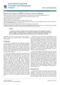
1. Introduction In recent years, composite materials have been used in interior automotive components because of their properties such as low weight, high specific stiffness, corrosion free, ability to produce complex shapes, high specific strength and high impact energy absorption etc. Therefore, this work is towards the development of an interior automotive component such as composite accelerator pedal for replacing it with the existing metallic one to reduce weight in conformation with safety standards. Most of the automotive accelerator pedals generally fail due to inappropriate decisions during selection of design concept, material and manufacturing process. In this work, Concurrent Engineering (CE) approach has been used to determine the most optimum decision on design concept and material of the composite accelerator pedal at conceptual design stage. In this view, development process is carried out under CE environment (Fig. 1). Comprehensive studies are performed to prepare Product Design Specification (PDS). Various Vol. 2 No. 4 (October 2011) ©IJoAT
561
International Journal of Advancements in Technology http://ijict.org/
ISSN 0976-4860
design concepts are generated using Morphological approach. In particular at design stage, 3-D solid modeling system is used to generate various design concepts followed by analysis on software package. Simultaneously, material selection is done on the basis of past research & PDS for accelerator pedal. Rating/weighting matrix evaluation method is used to select the best concept for the profile of pedal arm on basis of mass, volume, stress and deformation. Best design concept is selected through morphological chart on logical, conventional design and analysis results. Finally, prototype is prepared using SLS technique. Tab. 1 lists the various methodologies used in the development of composite accelerator pedal. Development of Composites
Design Specificatio ns
Material Selection
Idea Generation
Decision on final concept and material
CAD Model
Analysis Report
Matrix evaluatio n
Decision on Final Design
CAD Model
Analysis Report
Final Design
Rapid Prototyping using SLS Technology
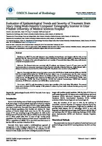
Figure 1: Development Process Table 1: Summary of Design & Development Methods Methods Used in/as Concurrent Engineering Philosophy throughout the study PDS Extensively for specification preparation Morphological For design concept generation Matrix evaluation For selecting the best concept Solid modeling For 3-D modeling of design concepts FEM For analysis of concepts RP For prototyping 1.1. Background Accelerator pedal consists of three main parts namely pedal plate, pedal arm and pivot shaft (Figure 2). It is usually close to floor which allows the driver’s heel to rest on the floor. It should not sink more than an inch or two, no matter how hard it is pressed with the foot; and the driver Vol. 2 No. 4 (October 2011) ©IJoAT
562
International Journal of Advancements in Technology http://ijict.org/
ISSN 0976-4860
should not feel as if he were stepping on a wet spongy pedal spells trouble in maintaining the vehicle speed. Existing accelerator pedal is made of metal possessing poor weight to strength ratio required for the working condition. It is highly prone to corrosion thus requires paint coating. Its parts are assembled by welding hence increases the number of processing steps, machine requirements. Moreover, pedal plate is needed to be covered with rubber pad for proper foot grip. It also gives poor internal damping. Pedal bracket Cable
Pivot shaft
Pedal plate Pedal arm
Figure 2: Accelerator Pedal 2. Literature Composites were introduced in the automotive industry from a quite time and had successfully replaced metallic parts because of increase in fuel efficiency by weight saving and corrosion resistance properties [1][5-6]. Sapuan [11-12] presented conceptual designs for the development of polymeric-based composite automotive bumper and pedal box system by using various methods of creativity, such as mind mapping, PDS, brainstorming, morphology chart, analogy and weighted objective methods. Murat [9] applied fiber reinforced polymers (FRP) for bus exterior and interior components. Gulur [7] presented a low cost fabrication for mono composite leaf spring and mono composite leaf spring with bonded end joints. Gummadi [8] presented a composite drive shaft for the replacement of conventional two-piece steel drive shaft. The design parameters were optimized with the objective of minimizing the weight of composite drive shaft. Concurrent Engineering, CAE and Rapid Prototyping techniques have also being applied for product development. Alemu [2] presented an approach to see and analyze different product development methods specifically on design for manufacturability and Concurrent Engineering studies. Bowonder [4] illustrated the use of concurrent engineering in an automobile firm Tata Motors. 3. Design Specifications The following factors are to be evaluated for preparing design specifications.
Vol. 2 No. 4 (October 2011) ©IJoAT
563
International Journal of Advancements in Technology http://ijict.org/
ISSN 0976-4860
Size: In view of the limited space available for the driver’s feet, the dimensions should be small as possible but must comply with safety and ergonomics standards. For dimensional reference, existing model of Mahindra make accelerator pedal is taken. Weight: In view of reducing the weight of accelerator pedal, it should have minimum weight. Material: As per the standards by regularized organizations of the automotive world, modulus of elasticity for the accelerator pedal must be greater than 888.6 MPa. Density of material should be less than density of aluminum i.e. 2700 kg/m3. The material should have high creep resistance, fatigue strength and corrosion resistance. The material should be used in high volume production and should be recyclable. Safety: The component must be free from sharp edges. The system must comply with all relevant parts of India and international legislation. The maximum force on the accelerator pedal is 40 N with a maximum deflection of 10 mm. Environment: The accelerator pedal must be capable of use in all weather conditions and should be non corrosive. It must be resistant to fuel slippage, greases and should not degrade by ultra violet radiation. The water absorption percentage of material must be less than 8 %. Ergonomics: The distance between steering wheel and accelerator pedal are kept approximately 600 mm. The return force should be between 40-60 N. The dimensions of pedal should not be too short so that drivers feel difficult to depress the pedal. The design must provide comfort and enough space installing and removal of the pedal. Design dimension should account factors for easy accessibility and women driving with high heeled shoes.
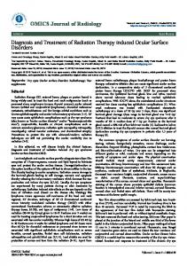
4. Material Selection Material selection process is carried out into phases; Selection of matrix and reinforcement composite materials (depicted in Figure 3). Finally, polyamide as matrix composite material and glass as reinforcement composite material are selected for accelerator pedal and its properties are shown in Table 2. Table 2: Material Properties of Glass Filled Polyamide Percentage of Glass Filling Tensile Modulus Tensile strength Possion’s ratio Flexural modulus Density Moisture Absorption Creep resistance Corrosion resistance Chemical Resistance
Vol. 2 No. 4 (October 2011) ©IJoAT
20 % by volume 5910 MPa 38.1 MPa 0.314 3300 MPA 840 kg/m3 0.30% Good Good Alkalis, Hydrocarbons , Fuels and Solvents
564
International Journal of Advancements in Technology http://ijict.org/
ISSN 0976-4860
Selection of Composite Material for Composite Accelerator Pedal
Selection of Reinforcement
Selection of Matrix Material
Particulate, Short fiber
Metal Matrix Ceramic Matrix Polymeric Matrix
Particulate composite Short Fiber composite Long Fiber composite
Flake composite
On basis of Low Weight Polymeric Matrix On the basis of Isotropic Concern Thermoplastics Thermosetting
Thermoplastics
Polypropylene Polystyrene Polyamide Polyethylene
Particulate, Short Fiber On basis of low weight, ease of manufacturing and recyclability Glass Carbon/ Graphite Metal Powders Kevlar On the basis of availability, inexpensive, high strength and stiffness
On basis of chemical resistance, cost, ease of manufacturing and easier availability
Polyamide
Glass reinforcement
Final composite material = Glass filled polyamide Powder
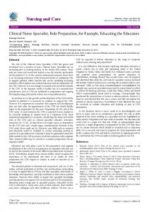
Figure 3: Flowchart for Material Selection 5. Concepts Generation Concepts generation for the composite accelerator pedal starts with formation of morphological matrix (Table 3). Then, the best pedal arm profile is selected out of six feasible profiles (Figure 4). Further, conceptual designs are modeled on CATIA. Fig. 5 shows the solid models of six Vol. 2 No. 4 (October 2011) ©IJoAT
565
International Journal of Advancements in Technology http://ijict.org/
ISSN 0976-4860
concepts having thickness 5 mm and overall profile dimensions of 15 x 15 mm2. The mass and volume of these concepts are found (Table 4). Table 3: Morphological Matrix for Composite Accelerator Pedal Solution
1
2
3
4
5
Compression spring
Spring in carburetor
Sub function
Means of controlling throttle valve Pedal connection to cylinder Pedal attachment to cable or cylinder Return force on pedal Pedal pad design
Pivot shaft location Pedal arm profile Ribbing pattern
Torsion spring
Hydraulic system
Pneumatic system
Hydraulic cylinder
Pneumatic cylinder
Cable
Shaft
Single slot
Double slot
Clevis pin
Torsion spring
Hydraulic force Design separately then attached Along pedal lever C X
Pneumatic force
Extension spring
U No ribbing
O 2 rows of V
Integral with pedal End pedal I V
of
T 2 Rows of X
Table 4: Mass and Volume Matrix Concepts Mass (g) Volume (cm3)
R
Concept 1
Concept 2
Concept 3
Concept 4
Concept 5
Concept 6
69.071 82.227
60.437 71.949
60.354 71.851
60.437 71.949
40.004 51.96
54.262 64.579
U
C
I
T
O
Figure 4: Feasible Pedal Arm Profiles
Vol. 2 No. 4 (October 2011) ©IJoAT
566
International Journal of Advancements in Technology http://ijict.org/
ISSN 0976-4860
Concept 1
Concept 2
Concept 3
Concept 4
Concept 5
Concept 6
Figure 5: Solid Models of Conceptual Designs of Accelerator Pedal Arm 6. Analysis Finite Element Analysis [10] is carried out on all the design concepts using ANSYS work bench for material properties of Glass filled Polyamide i.e. tensile modulus of 5910 MPa, Poisson ratio of 0.314 and density of 840 kg/m3. After fixing at the desired location, force of 40 N is applied and total deformation and equivalent Von-Mises stress for six design concepts are obtained (Figure 6 & 7 and Table 5).
Concept 1 Vol. 2 No. 4 (October 2011) ©IJoAT
567
International Journal of Advancements in Technology http://ijict.org/
ISSN 0976-4860
Concept 2
Concept 3
Concept 4
Vol. 2 No. 4 (October 2011) ©IJoAT
568
International Journal of Advancements in Technology http://ijict.org/
ISSN 0976-4860
Concept 5
Concept 6 Figure 6: Deformation Distribution for Composite Accelerator Pedal Arm
Concept 1
Vol. 2 No. 4 (October 2011) ©IJoAT
569
International Journal of Advancements in Technology http://ijict.org/
ISSN 0976-4860
Concept 2
Concept 3
Concept 4
Vol. 2 No. 4 (October 2011) ©IJoAT
570
International Journal of Advancements in Technology http://ijict.org/
ISSN 0976-4860
Concept 5
Concept 6 Figure 7: Stress Distribution for Composite Accelerator Pedal Arm Table 5: Total Deformation and Stress Matrix Concepts Deformation (mm) Von-Mises Stress (N/mm2)
Concept 1 7.3589
Concept 2 7.5106
Concept 3 9.025
Concept 4 7.8702
Concept 5 15.058
Conce pt 6 12.58
9.9851
10.187
13.34
10.592
24.163
17.16
7. Best Design Concept In order to select the best design concept for composite accelerator pedal arm, rating/weighting matrix evaluation method is used. From Tables 4 & 5, all the concepts are compared and concept 1 is selected as the reference on the basis of maximum mass, maximum volume, least deformation and least stresses. The relative mass, volume, deformation and stress to concept 1 are taken as reference parameters and the corresponding values for other concepts are calculated in comparison to concept 1 (shown in Table 6). Further, the weighting factor for each criterion is applied to evaluate the highest ranked design concept as best one. Then, each concept is rated on the basis of reference scores on scale from 1 to 5 by comparing relative values based on the criterions of minimum mass, maximum deformation and maximum stress Vol. 2 No. 4 (October 2011) ©IJoAT
571
International Journal of Advancements in Technology http://ijict.org/
ISSN 0976-4860
Table 6: Relative Mass, Volume, Deformation and Maximum Stress as Compared to Concept 1
Concepts
Mass ratio
Volume ratio
Deformation ratio
Equivalent Von-Mises Stresses
Concept 1 Concept 2 Concept 3 Concept 4 Concept 5 Concept 6
1 0.875 0.874 0.875 0.579 0.786
1 0.875 0.874 0.875 0.632 0.785
1 1.021 1.226 1.069 2.046 1.709
1 1.02 1.336 1.336 2.42 1.719
(Table 7). Lastly, decision matrix is evaluated by multiplying the each concept rating by weight factor assigned for each criterion. The weight factor is on the scale from 1 to 5. Total highest score of 51 for concept 2 (Table 8) is thus selected as the best design concept for the composite accelerator pedal arm [3], [13]. Table 7: Rating Matrix for Design Concepts Criteria Minimum Mass Maximum Deformation Maximum Stress
Rating Concept 2 2
Concept 3 3
Concept 4 2
Concept 5 5
Concept 6 4
5
3
4
1
2
5
3
4
1
2
Table 8: Matrix for Evaluation of Best Concept Criteria Minimum Mass Maximum Deformation Maximum Stress Total
Weight Factor
Weight Factor x Rating
3
Concept 2 6
Concept 3 9
Concept 4 6
Concept 5 15
Concept 6 12
5
25
15
20
5
10
4
20 51
12 36
16 42
4 24
8 30
Based on logical choice, conventional designs and results for best pedal arm profile, final set of sub function is selected for development of composite accelerator pedal. Further, solid model of the selected accelerator pedal is created using CATIA software package (Fig. 8). Pedal pad and pivot shaft is made integral with pedal arm. ’V’ ribbing is provided to add stiffness and strength. Necessary fillets are also provided for aesthetics and removing sharp edges. Figure 9 shows the Vol. 2 No. 4 (October 2011) ©IJoAT
572
International Journal of Advancements in Technology http://ijict.org/
ISSN 0976-4860
total deformation and equivalent stress distribution. Table 9 summarizes the analysis result and it is revealed that stress and deformation are well under safe values on comparison with material properties. Table 9: Final Morphological Matrix Solution
1
2
3
4
5
Torsion spring
Hydraulic system
Pneumatic system
Compression spring
Spring in carburetor
Hydraulic cylinder
Pneumatic cylinder
Cable
Shaft
Single slot
Double slot
Clevis pin
Torsion spring
Hydraulic force
Pneumatic force
Extension spring
Integral with pedal
Design separately then attached
Pivot shaft location
End of pedal
Along pedal arm
Pedal Arm profile
I
C
U
O
T
Ribbing pattern
V
X
No ribbing
2 rows of V
2 Rows of X
Sub function
Means of controlling throttle valve Pedal connection to cylinder Pedal attachment to cable or cylinder Return force on pedal Pedal pad design
Figure 8: Solid model of Final Composite Accelerator Pedal Vol. 2 No. 4 (October 2011) ©IJoAT
573
International Journal of Advancements in Technology http://ijict.org/
ISSN 0976-4860
8. Prototyping Prototype of the composite accelerator pedal is created by using SLS machine. Its pictorial view is shown in Figure 9 and characteristics of the prototype developed are summarized in Table 10.
(a)
(b)
Figure 9: Deformation and Equivalent (Von-Mises) Stress Distribution for Composite Accelerator Pedal Table 10: Analysis Report for Composite Accelerator Pedal
Final Pedal
Mass (g)
Volume (cm )
Deformation (mm)
100
119.13
1.5749
Vol. 2 No. 4 (October 2011) ©IJoAT
3
Equivalent (Von-Mises) Stress (N/mm2) 4.34
574
International Journal of Advancements in Technology http://ijict.org/
ISSN 0976-4860
Figure 10: Prototype of the Composite Accelerator Pedal Table 11: Characteristics of the Prototype Generated by SLS Technology
Characteristics of composite accelerator pedal Approx. 9 hours Machine Time 1 -6.2 µm Surface Finish Yellowish Colour 100 g Weight of Component Not fragile but thin sections can easily Experience During Handling broken 9. Concluding Remarks The development process of composite accelerator pedal has been carried to replace the existing metallic accelerator for various benefits. It is observed that the composite accelerator pedal weighs 100 g while the reference existing model weighs about 500g, thus gives the weight reduction of 80%. It is produced as a single unit so, gives lower manufacturing complexities, better fit and better finish. Moreover, it is also found to be dimensional stable that makes it suitable for usage in a wide range of temperature. It is non-corrosive and could be worked without requirement paint coatings. It has an inherent resistance to fuel, oil and greases suitable for usage. It is inherently better sound insulator than steel. There is also further scope of development of other automotive components such as brake and clutch pedals and even the brackets used for mounting the pedals with composite material for higher weight savings and durability on the same context. References [1] [2]
Aljibori, S.; Hakim, S.: Fiber Reinforced Composites (FRC) structures with potential applications: literature review, International Journal of Applied Engineering Research, 4(10), 2009, 1939-1954 Alemu, M.-B.: Design for manufacturability and concurrent engineering for product development, World Academy of Science, Engineering and Technology, 49, 2009, 240-246.
Vol. 2 No. 4 (October 2011) ©IJoAT
575
International Journal of Advancements in Technology http://ijict.org/
[3]
[4] [5] [6]
[7] [8] [9] [10]
[11] [12]
[13]
ISSN 0976-4860
Adrian, X.; Simon, S.-P.; Theo, F.: A comparison of concept selection in concept scoring and axiomatic design methods, Presented to Canadian Congress on Engineering Education, Canada, Paper No. 69, 22 – 24 July, 2007 Bowonder, B.: Concurrent engineering in an Indian automobile firm: the experience of Tata, International Journal of Manufacturing Technology and Management, 6(3/4), 2004. Denise, C.; Hiroyuki, Y.; Sunao, F.; Christian, L.; Kasserra, P.-H.: Application of nylon composite recycle technology for automotive parts, Proceedings. JSAE Annual Congress 107-02, 2002,1-4 Fuchs, E.-R.-H.; Field, F.-R; Richard, R.; Kirchain; Randolph, E.: Strategic materials selection in the automobile body: economic opportunities for Polymer Composite Design, Journal of Composite Science and technology, 66(9), 2008, 1989-2002 Gulur, S.-S.-S, Sambagam, V.: Mono composite leaf spring for light weight vehicle design, end Joint analysis and testing, Journal of Materials Science, 12(3), 2006, 220-225 Gummadi, S.-A.-J.-K.: Optimum design and analysis of a composite drive Shaft for an automobile, Master’s degree Thesis, Blekinge Institute of Technology Karlskrona, Sweden, 2006. Murat, O.: The use of composite materials in automotive industry, M.Sc. Thesis, Institute of Natural and Applied Sciences, Cukurova University, Turkey, 2010. McMahon, C.-D.; Scott, M.-L.: Innovative techniques for the finite element analysis and optimization of composite structures, 23rd International Congress of Aeronautical Sciences, Toronto, Canada Page No. 61, 813 September, 2002. Sapuan, S.: A conceptual design of the concurrent engineering design systems for polymazcaeric-based composite automotive pedals, American Journal of Applied Science, 2, 2005, 514-525. Sapuan, S.-M.; Maleque, M.-A.; Hameedullah, M.; Suddin, M.-N.; Ismail, N.: A note on the conceptual design of polymeric composite automotive bumper system, Journal of Materials Processing Technology, 159, 2005, 145–151. Shun, T.; Kosuke, I.: Modifying Pugh’s design concept evaluation methods, ASME Design Engineering Technical Conferences, USA, 4, 2004, 1-10.
Vol. 2 No. 4 (October 2011) ©IJoAT
576