INTERNATIONAL CONFERENCE ON ENGINEERING DESIGN, ICED’07 28 - 31 AUGUST 2007, CITE DES SCIENCES ET DE L'INDUSTRIE, PARIS, FRANCE
CONFIGLAB: A CONCEPTUAL DESIGN TOOL WITH CORRECTIVE EXPLANATIONS SUPPORTED BY SKETCH-BASED DESIGN REUSE Noel Titus1, Barry O’Sullivan2 and Karthik Ramani1 1
Purdue Research and Education Centre for Information Sciences and Engineering, Purdue University, USA 2 Cork Constraint Computation Centre, Department of Computer Science, University College Cork, Ireland ABSTRACT While conceptual design is widely regarded as one of the most important phases of the product development process, very few tools exist that support designers at this critical phase. Designers find it natural to sketch when developing concepts. In this paper we present a framework for supporting the conceptual design of mechanical systems through a sketch-based design reuse tool. Design retrieval based on sketching is used to bridge the gap between design intent captured in user sketches and concept realization. During design, designers also need advice on the implications of their design decisions. The design support system developed here can generate concise corrective explanations when required. The explanation framework informs the user of violated constraints and suggests corrective actions to eliminate violations based on a product taxonomy and shape similarity metric. We describe the tool, CONFIGLAB, and present a case-study to demonstrate our approach. Finally, we summarize our research agenda in this area, highlighting the key issues that need to be addressed. Keywords: Conceptual design, sketching, constraints, explanations, design reuse. 1 INTRODUCTION The ideal support tool for design would be one that supports the design activity in such a manner as to allow for innovation by combining original design and design reuse. Preferably, this support will begin early in the process, i.e. during conceptual design. The support tool would allow the designer to pursue design activities in an interactive manner, through activities such as sketching, and by allowing for the gradual evolution of the design. The system should allow the designer the flexibility of working at the desired level of abstraction and provide feedback to the designer regarding his decisions. The current system, CONFIGLAB, allows the designer to combine existing designs in novel ways. It forms a component of a system that integrates design reuse and innovative design with sketching, semantics and behavior. This tool focuses on: 1. Sketching: In this activity, the designer draws representative shapes of the design concepts. 2. Design reuse: The sketch is used to trigger design retrieval from a database. The search process provides the link between the conceptual design sketch and the physical realization of the design. Design reuse occurs in two ways: one is design reuse as-is without modification and the other is design reuse with modifications. The system currently implements the former. 3. Context in design retrieval: Context is imparted to the retrieval by adding design constraints. Constraints reflect the scenario in which the current design in being developed. Retrieval utilizing the knowledge contained in constraints produces more relevant results. 4. Providing corrective explanations: Explanations provide feedback for the design decisions made by the designer. They indicate violated constraints, which design components contribute to the violations, and suggest corrective actions to circumvent the violations. The main contribution of the current work is a framework for supporting the conceptual design of mechanical systems using a sketch-based design reuse tool. The paper is organized as follows. Section 2 explains the justification and motivation for the functionality provided in the current prototype. Section 3 provides an overview of the system and describes the algorithms and implementation issues encountered in this prototype. Relevant literature is also discussed in this
ICED’07/668
1
section. This is followed by a case study in Section 4. Finally, in Section 5 we summarize the research done so far and highlight future directions to be taken. 2 CONCEPTUAL DESIGN SUPPORT Engineering conceptual design can be regarded as that phase of the design process during which the designer takes a specification for a product to be designed and generates many broad solutions for it. It is generally accepted that conceptual design is one of the most critical phases of the product development process. Over 75% of a product’s total cost is dictated by decisions made during the conceptual design phase. Poor conceptual design can never be compensated for at the detailed design stage [8, 9]. Hence, it is important to support this activity in a manner as to allow explorative, creative conceptual design by leaving routine tasks such as constraint solving to the computer. With few exceptions, existing approaches to supporting conceptual design tend to focus on the non-sketching aspects of conceptual design. A structured method for generating solutions in the form of digital sketches by specifying the required function is outlined in [18]. The SketchIT system developed in [25] is capable of taking a stylized sketch as input from which the behaviors that the parts provide is extracted and abstracted to a “qualitative configuration space” from which families of new designs are synthesized. Alvarado and Davis have developed a sketch recognition environment that recognizes circular and polygonal bodies, forces, pin joints etc. and runs a simulation of the sketched dynamic mechanical system using the Working Model software [2]. Our system has been motivated by these works. The importance of the design activities mentioned in the introduction are discussed below. 2.1 Sketching Sketching is critical in the mechanical engineering design process. When a design is being conceptualized, designers use sketches as a means of developing, exploring and communicating the design. Ullman et al. carried out design studies that showed drawing (both formal drafting and sketching) is the preferred method of external data representation by mechanical engineers [26]. Sketching is particularly important since it serves graphical representation needs not supported by drafting. Ullman et al. found that for the problems given to the human subjects, 48% of the “marks-onpaper” (which included sketching, drafting, text, dimensions, and calculations) were sketching related, whereas only 24% were drafting (marks involving use of drawing instruments) related. 2.2 Design reuse In an article in Scientific American [6], it was estimated that “only 20% of the parts initially thought to require new designs actually need them; 40% could be built from an existing design and 40% could be created by modifying an existing design”. According to Clausing [4], the principal objective in product development is “achieving the best strategic balance between reuse and innovation”. Hence, it is imperative that existing design knowledge is both reusable and available to designers during critical decision making stages in conceptual design. In the past decades, a large number of 2D and 3D models have been produced in engineering fields. They serve as a means to express and communicate design ideas. Reusing and sharing the knowledge embedded in the two representations is becoming an important way to accelerate the design process, improve product quality, and reduce costs. The sketch-based design reuse method described here provides the bridge between the sketching done during conceptual design and the realization of the product. 2.3 Context in design retrieval Context in engineering design refers to the needs and requirements for which the product is being designed. It is expressed in terms of the values of attributes of a design concept. In knowledge management these attributes are structured in the form of a knowledge representation schema. Capturing context through various knowledge representation schemas is widely used in design problem solving methodologies such as case based reasoning [1, 15], design rationale systems [24], and other works [3, 13]. This work represents attributes using a product representation schema derived from the database model in [28]. Utilizing these attributes in the constraints, the relevancy of the retrieved results from the search process is increased.
ICED’07/668
2
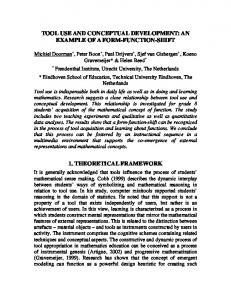
2.4 Corrective explanations In an interactive product design system, explanations are a way of providing feedback to the designer to aid in the decision making process. The explanations should be not be confined to a justification of the problem solving trace but identify reasons for a failure to help understand why features have been selected or eliminated [7]. With explanations, the designer can focus on higher-level cognitive tasks of creatively putting together a system for the design task at hand since the system handles the constraint consistency checking and informs the designer when inconsistent decisions are made. Currently, systems that implement truth maintenance in configuration systems have focused on blame i.e. which component or set of components are the offending agents. In this prototype, we go one step further, implementing both minimal conflict explanations [11, 12] as well as corrective explanations [16], in which candidate components that can be substituted to circumvent the violations are suggested. Informally, a minimal conflict explanation is a subset of the components in the design problem that is sufficient to cause conflict, but that no proper subset of those components can. A corrective explanation is a component or a set of components that can replace the offending set of components that will allow the designer to move at least one step further from the current dead end imposed by the conflict. 3 CONCEPTUAL DESIGN SUPPORT SYSTEM Conceptual design in CONFIGLAB is enabled by allowing the designer to creatively combine old designs to develop innovative products for new or different applications. It allows for the sketching and incorporation of working principles and behavior as constraints. The designer is able to draw concepts as well as evaluate different working principles to achieve the desired product functionality. The bridge between the sketch and realization of the concept is provided via search and retrieval. Constraint-based approaches for functional decomposition and function-means maps such as the work presented in [17] can be implemented as a precursor to this system. This section will present the system architecture for conceptual design support, implementation and also discuss some relevant literature. 3.1 System architecture The architecture of the CONFIGLAB system is show in Figure 1 below.
Figure 1: Architecture of the CONFIGLAB conceptual design support system.
The designer begins by defining constraints on attributes picked from a predefined list obtained from the product representation schema. The methodology is explained further in Section 3.2. Once the constraints have been defined, the designer draws a sketch via the user interface. When the designer is satisfied with the sketch drawn, he triggers the retrieval process. The sketch-based retrieval is explained in Section 3.3. The system searches the design database for similar parts and produces a ranking for all components in the system. Images of the search results can be viewed in the pop-up results browser. As the designer browses the results, he can either select a component or refine the
ICED’07/668
3
sketched query. After the designer has made some choices, it is possible some constraints will be violated for the current query results and it is necessary to explain to the designer how to recover from this situation. The ranked list of search results and the associated attribute data for each component is used by the system to compute explanations based on the constraints defined by the designer. A unique interface provides feedback to the designer by highlighting which components violate the constraint system. The designer can obtain both minimal conflict [11] and corrective explanations [16] for any violating component. Details of the explanation procedure are provided in Section 3.4. Following the browsing of search results and explanations, the designer can either select a component for use in the design and continue the process of defining constraints, or can terminate the design process. Similar works include the design reuse tool SyDer [5], and a conceptual design tool using principle solution elements described in [27]. Both use a constraint network and a truth maintenance system for consistency checking. Unlike SyDer, CONFIGLAB carries out the consistency checks and provides minimal conflict explanations before the designer commits to a particular concept resulting in less iteration on the designer’s part. Furthermore, SyDer does not provide corrective explanations, nor does it provide a sketch-based interface. 3.2 Product representation for constraint definition and context creation Computation of explanations on constraints defined using attributes necessitates a representation for those attributes for parts in the design database. The product representation schema adopted here is a derivation of a design database representation model presented in [28].
Figure 2: Product representation schema.
Modifications were made to the product representation in [28] to the flow field, where a “ports” field was added and flow was classified into “mechanical translation”, “mechanical rotation”, “electrical”, “fluid” and “thermal” domains. Such classification appears commonly in systems dynamics, where the unified variables of effort, flow, displacement and momentum are used to describe the storage, transmission and transformation of power in a physical system [14]. This classification was adopted since working principles, which are represented using mathematical equations, generally fall into those domains. A condensed representation of the schema along with an example for a brake calliper from the case study in Section 4 is shown in Figure 2. When computing corrective explanations, it is necessary to replace a violating component with one that is not only similar in shape but also possesses a similar set of attributes. For this purpose, in
ICED’07/668
4
addition to its object representation, we associate with every component an attribute vector (an ordered tuple) composed of its numerical attributes. The numerical attributes are a subset of the attributes in the product representation schema and consist of dimensional, weight, flow, and behavioral attributes. The use of the attribute vector is discussed further in Section 3.4.2. While the representation schema adopted here is rigid, future versions of the prototype will include a flexible and customizable representation schema. The future work in this area will capture the semantics of the user’s needs and specifications more effectively. 3.3. Sketch-based retrieval of engineering parts Designers prefer to express their creative design ideas through freehand sketches [22]. Sketching is particularly suited to the conceptual phase of the product design cycle for the generation and communication of designs. The reuse component of CONFIGLAB, called SHAPELAB, allows for searching for similar 3D shapes in an engineering part database based on a freehand sketch query.
Figure 3: System architecture for sketch-based 2D and 3D shape retrieval.
The framework for SHAPELAB is shown in Figure 3. The shape retrieval framework is supported by four key components: pose determination for 3D models; 2D orthogonal view generation based on multiple levels of detail; similarity measurement between 2D shapes; and a freehand sketchbased user interface. This section will discuss the “level of detail” representation of database components since it has a bearing on the abstraction level of the user sketch handled by the system, and the user interaction with the user interface. In addition, the interoperability of the system with other design tools will be discussed. A detailed description of the system in its entirety including the similarity metrics used for retrieval is presented in [19], [20] and [21]. 3.3.1 User-interface and sketch editor
SHAPELAB has a user-friendly graphical interface for supporting 2D&3D shape retrieval. The following functionality is offered by the user interface. 1. Designers express their intent by sketching a 2D shape in the sketch-editor. The user draws at least one and up to three sketches corresponding to each of the three orthographic views of the component he is visualizing. The sketch-editor works with either a mouse or pen input and offers edit, erase, rotate, zoom, and view copy operations. 2. Through the interface users can emphasize certain views by specifying weights for a view. 3. Once the search button is clicked, the pop up window shows the search results in ranked order. 4. The design process forms an iterative loop by which users can repeatedly refine the search results until satisfactory results are obtained. This is enabled by allowing the user to reuse a retrieved result as a query with or without modifying it in the sketch-editor, using a query-byexample approach. A screen shot of the user interface is presented in Figure 7(a). 3.3.2 Sketch abstraction: Level of detail
The design paradigm followed in this work is that the link between the user’s sketch representing the conceptual design and the realization of the final design specifications is through search [10]. Factors such as the skill of the designer in sketching, the number of sketch details, such as geometric features,
ICED’07/668
5
relative location of sketch entities, such as lines and arcs, have an influence on this paradigm. Since the abstraction level of the user sketch is unknown a-priori we use three levels of detail in the representation of the components in the design database. They are the contour level, silhouette level, and drawing level, as shown in Figure 4.
Figure 4: Multiple levels of detail: (a) Original model (b) Contour (c) Silhouette (d) Drawing. The algorithms to generate these views from triangulated STL (stereolithography) files are given in [23]. While the abstraction level of the user sketch is immaterial, it was found that a combined linear weighted sum of distances of the sketch from the three levels of detail gave the best search results. 3.3.3 Interaction with aspect models
It is impossible to capture all the necessary information in the shape and product representation schema for the conceptual design. To describe all aspects of a design, it is necessary to use computeraided design (CAD) models, dynamic simulation models, etc. These models, called aspect models, partially describe a design, and are a part of a general product model. It becomes imperative to link the current system to external software modules that are better able to represent the design. While not currently implemented, in the future, the parameters and constraints of an instantiation of our product model will be coupled to external aspect models. 3.4 Generating corrective explanations Early design is a trial and error process and hence building a system that allows the designer to interactively solve problems by adding, removing and modifying constraints is of primary importance. In CONFIGLAB, we aim to guide the designer’s component selections to a desired solution, based on the specified constraints, without having to resort to blind backtracking. Furthermore, when a designer encounters a situation where the design decisions made have resulted in an inconsistency, it is useful for the interactive system to generate explanations that identify causes of violations and suggests corrective actions, allowing the design to progress forward. In this section, we explain the notion of corrective explanations and the methodology developed to compute them. 3.4.1 Corrective explanations
Generating corrective explanations [16] for an inconsistent constraint system involves finding a set of alternative assignments for a subset of the constraint variables so that consistency is recovered. We will use the example of a designer designing a rack and pinion steering mechanism (Figure 5) to explain the notion of corrective explanations. Of the various components in the system, the designer has made decisions for the steering column, the rack, pinion and yoke to be used (the boxed components in Figure 5) from the simplified set of choices available. A decision needs to be made for the type of bearing base to be selected while satisfying the constraints for the system, as shown in Figure 5. As it can be seen, neither choice for P5, i.e. the bearing base, enables us to satisfy the overall weight constraint with the current part choices. An examination of the example will show that a plausible causal explanation would assign blame to the choices for parts P3 and P4 for the dead end that has resulted. This is because bearing base 1 is incompatible with pinion 1 (P3) and yoke 2 (P4) on account of their violation of the respective diameter constraints. Furthermore, the diameter constraint between bearing base 2 and yoke 2 (P4) is not satisfied. The designer backtracks to part P4, the point where the last choice was made and selects yoke 1, which is incompatible with the choice for part P1 since the diameter constraint is violated. The designer would then backtrack to part P3, the other part causing the inconsistency. However, on selecting pinion 2 for part P3, the system indicates that this is incompatible with the choice for part P2, viz. rack 2. This will lead to futile backtracking and
ICED’07/668
6
frustration on the designer’s part. Despite the changes made by the designer, he is unable to move forward in the design process.
Figure 5: Example of rack and pinion steering for corrective explanations. However, a corrective explanation which will permit the designer to move forward can be found on the basis of changing the choices for part P1 and P4. By selecting steering column 2 for part P1 and yoke 1 for part P4, while keeping all other choices the same, the designer will be able to select bearing base 2 for part P5. This represents a forward progression of the design process. It should be noted that the explanation may not be in terms of the current part, but in terms of other parts that were included in the design that have to be changed now. Hence, the set {P1, P4} represent the corrective explanation for this constraint problem. In general, there can be more than one set of corrective explanation for a given constraint problem. 3.4.2 Methodology for generating corrective explanations
Now that the notion of corrective explanation has been discussed, the next step is to delve into the methodology to compute corrective explanations. The algorithm, CORRECTIVEEXP, used for generating corrective explanations is given in [16]. While the algorithm applied here remains unchanged from that of CORRECTIVEEXP some specifics pertaining to our system are explained here. 3.4.2.1 Constraint types and constraint networks. Constraints currently being handled are of two types: value assignments (a numeric value that is assigned to a parameter) and algebraic constraints (a formula, equation or inequality). The constraints between the attributes in the current prototype are added incrementally. As stated earlier, the designer specifies constraints on attributes from a predefined list of attributes contained in the product representation schema (Section 3.2). This schema will be made extensible in the future in the event a new part is added to the design database that has additional attributes not in the current product representation schema. The constraint network is created as follows. The designer specifies constraints on the attributes for the first query, sketches the query and retrieves components of which one is selected. Following the first retrieval step, for all further queries, the designer can specify constraints that link the attributes of any of the prior selected part instances to the attributes of the yet unknown components that the designer anticipates obtaining in the next query. Once the constraint network is formed, it is necessary to check the constraints for consistency and also compute explanations if required.
ICED’07/668
7
3.4.2.2 Consistency of constraints. Since this is a design reuse process, it is not necessary to propagate values through the constraint network because the attribute values for any component in the database are known. Instead, it is necessary to detect inconsistencies in the value assignments for variables in the constraint network. We have currently programmed the methods detecting inconsistencies for simple algebraic constraints in C++. In the future, when we intend to handle behavioural constraints that are more complex, such as dynamical constraints which involve differential equations, we will link to an external solver such as Matlab or Maple. 3.4.2.3 Computing the corrective explanations. In order for the system to suggest corrective explanations, alternate components need to be suggested that can suitably replace the components causing the inconsistency. The alternate components can be suggested in a number of ways. The first method to find components for explanations is to use the rankings of the components returned from the shape search system in response to the user sketch query. If the user’s first choice of component for a query results in an inconsistency, then the next highest ranked component not causing an inconsistency can be used in a corrective explanation. A subset of the ranked parts for each query can be stored to form a domain of parts from which corrective explanations can be generated. The designer can specify at the beginning of the design process that the first n-parts (where n is a finite natural number bounded by the number of parts in the database) from the rankings for each search be stored for the purpose of corrective explanations. The second approach is similar to the first, but instead of using the rankings from the sketch query, the first component choice of the designer is used as a query-by-example and a subset of the ranked parts are used for computing corrective explanations. The third approach is for the designer to pick a fixed number of parts after each query that can be used as replacements in the corrective explanation. This method is less automated and involves more designer input than the first two methods. The automated approach using rankings provides reasonable results. However, since the shape representation used in the shape similarity metric has less than perfect precision, it may cause parts the designer does not consider similar to appear in the subset of components used in computing corrective explanations. This is not a desirable situation. To circumvent the above drawback we invoke the attribute vector idea discussed in Section 3.2. The attribute vector is formed as an ordered tuple of every numerical attribute of every component in the design database. It has the same dimension, for every component in the database. If a component possesses a certain attribute, then the corresponding location in the attribute vector is assigned a value of 1, otherwise it is assigned a value of 0. Consider, for example, that the design database is comprised of just two types of components, motors and centrifugal pumps. The centrifugal pump is described by its weight (W), cost (C), volume flow rate (Q), speed (N), and pressure head (H). Attributes of the motor are weight, cost, operating voltage (V), speed, and efficiency (e). The attribute vector would be composed from all the attributes of the motor and pump and is represented by the following tuple: . The attribute vector representation of the pump would then be and for the motor would be . _
_
We now define a query vector Q and a part vector P . When a designer specifies constraints on certain attributes during the retrieval and constraint network creation process, the corresponding locations for the constrained attributes are assigned a value of 1 in the attribute vector, and this forms the query vector. The part vector is the attribute vector description of the components in the design database described above. In order to ensure that corrective explanations are formed only from a subset of parts that the designer considers similar to be one that needs to be replaced, we match the user query on both shape representation and attributes. If a component in the design database possesses the same attributes as the constrained attributes in the user query, the likelihood of it being similar to what the user has in mind is higher. The attribute match between the query and the component is done using the query similarity metric given in equation (1). _
Query similarity S =
_
Q.P _
(1)
_
Q .Q
ICED’07/668
8
Using the centrifugal pump and motor example, say the designer is searching for a pump. The designer constrains the weight, volume rate, and speed from the pull down attribute list. The query _
_
vector would then be Q = . The pump attribute vector is P p = _
and the motor vector is P m = . Computing the terms in equation (1), we get: _
_
_
_
_
_
Q . P p = 3; Q . P m = 1; Q . Q = 3. The query similarity for the pump and motor respectively are: _
_
_
_
Q. P 3 1 Sp = _ _ = = 1 and Sm = _ _m = = 0.33 3 3 Q .Q Q .Q Q. P p
The value of the query similarity metric for the pump is 1, but only 1/3 for the motor, indicating that the pump has greater similarity to the query than the motor. Hence, using this similarity metric the system begins to put together a subset of parts that are similar to the user query and is able to avoid having dissimilar components in the corrective explanation. There are limitations to this approach since it relies on an exact attribute match. In the future, flexibility to this approach will be introduced to the matching process using ontology and semantics. 4 CASE STUDY Consider the case of a mechanical engineer designing a floating calliper disc brake with radial brake pads for an automotive application. Some of the components of the brake system and associated attributes (light blue boxes) and constraints (grey boxes) between them are shown in Figure 6.
Figure 6: Partial constraint network for the disc brake system. The designer begins by specifying a set of user defined requirements using a variable–value pair in the “design” tab of the user interface, which is shown in Figure 7(a). These variables associated with the requirements appear in the constraints defined between attributes of the components being retrieved via sketching (e.g. braking distance Sbr in Figure 6). Following this, if the designer so desires, he can specify constraints on any attributes from a pull down menu for the part to be retrieved; all part attributes are available through this constraint editor dialog. The designer has sketched a brake shoe in Figure 7(b), for which the system retrieves candidate parts. Note that in this window, parts that would cause a conflict with the design constraints if they were added to the design are highlighted with a strong (red) border. In this example, the designer has selected part #10. Based on the set of parts the designer has previously introduced into the design,
ICED’07/668
9
which have not been shown for space reasons, the inset in Figure 7(b) shows a set of parts sufficient to cause inconsistency for part #7. This inconsistency is on account of the violation of the constraint that relates the thicknesses of the brake pads, disc, calliper body length and spring deflection. Following the selection of a part, constraints can be specified between attributes of previously retrieved parts and the anticipated attributes of the component, available in the pull down menu, to be retrieved in the next query. The designer specifies the constraints between attributes of the brake shoe and the disc to be selected in the next query. Subsequent to this, the designer sketches the disc and retrieves results which are shown in Figure 7(c). Part #39 is shown in the retrieved results in Figure 7(c), which the designer desires to use, is inconsistent with prior choices. Since the designer wants to use this but cannot because of the inconsistency, the designer triggers the corrective explanation for this disc. As indicated by the corrective explanation in Figure 7(d), the designer needs to replace the prior choices for the brake support pads and calliper body with the alternatives shown. An iterative process such as this continues (Figure 1) until the designer terminates the design activity. From an evaluation point of view, while no formal timing analysis has been performed, the response time of the system in terms of part retrieval and explanation generation have been sufficiently fast for interactive design.
Figure 7: (a) User interface (b) Brake shoe search results showing minimal conflict explanation (c) Disc sketch with search results (d) Corrective explanation for disc. 5 CONCLUSIONS We have presented a sketch-based tool for supporting the conceptual design of mechanical systems and demonstrated it on a real world example. The tool has the ability to retrieve parts from a database based on sketches that the designer can combine in novel ways to develop new products. It can generate explanations when the design is inconsistent with the constraints that it must satisfy. In the future we will address a number of issues that must be resolved before our system can be deployed in a real world context. Firstly, the language that the designer uses to express the set of constraints, that
ICED’07/668
10
the design must satisfy, must be extended. As the complexity of these constraints is extended the complexity of checking the design for consistency becomes more complex. There are a variety of avenues we can pursue here. At the moment, the view that the designer has of the evolving design is quite limited since only one design is being developed. Rather than the part-by-part view we have presented, an overall design view should be available to the designer. However, in general, designers want to be able to work at a high-level of abstraction where there are many possible allowed part configurations to fulfill the design. We will study the issues involved in allowing the designer to select multiple possible parts for each aspect of the sketch. We can then use traditional constraint satisfaction techniques to ensure that there is at least one consistent design possible as the design process continues. Additionally, we will enhance the system to include functionality that will allow the designer to realize the objective of “achieving the best strategic balance between reuse and innovation” [4] in new product design. Evaluation of the system will be conducted by studying engineers using the system and determining different metrics such as number of iterations required with and without the system. 6 ACKNOWLEDGEMENTS The authors from Purdue University would like to thank the Purdue Discovery Park Center for Advanced Manufacturing (CAM) for partially supporting the work presented. Barry O'Sullivan is supported by Science Foundation Ireland (Grant Number 05/IN/I886). REFERENCES [1] Aamodt, A., Plaza, E.,; Case-Based Reasoning: Foundational Issues, Methodological Variations, and System Approaches, AI Communications, 1994, Vol. 7(1), 39-59. [2] Alvarado, C., and Davis, R. 2001. Resolving ambiguities to create a natural computer-based sketching environment. In Proceedings of the 17th International Joint Conference on Artificial Intelligence (IJCAI-2001), 1365–1371. [3] Bilgic, T. and Fox, M. S., Constraint-based retrieval of engineering design cases: context as constraints, in J. S. Gero & F. Sudweeks (eds), Artificial Intelligence in Design, (1996), Kluwer Academic Publishers, Dordrecht, 269-288. [4] Clausing, D. P. 1998. Reusability in product development – keynote address. In Proceedings of Engineering Design Conference on Design Reuse. [5] Feldkamp, F., Heinrich, M., and Meyer-Gramann, M. D., SyDer – System design for reusability, Artificial Intelligence for Engineering Design, Analysis and Manufacturing, 1998, 12: 373-382. [6] Gunn, T. 1982. The mechanization of design and manufacturing. Scientific American 247:114– 130. [7] Hagg, A., Junker, U., O’Sullivan, B., A Survey of Explanation Techniques for Configurators, Proceedings of ECAI-2006 Workshop on Configuration, August 2006 [8] Hsu, W., and Liu, B. 2000. Conceptual design: Issues and challenges. Computer-Aided Design 32(14):849–850. [9] Hsu, W., and Woon, I. M. Y. 1998. Current research in the conceptual design of mechanical products. Computer- Aided Design 30(5):377–389. [10] Pu , J., Titus, N., and Ramani, K., A New Design Paradigm Based On Sketch And Retrieval, ASME 2006 International Design Engineering Technical Conferences & Computers and Information in Engineering Conference, September 2006, DETC2006-99381. [11] Junker, U. 2001. QUICKXPLAIN: Conflict detection for arbitrary constraint propagation algorithms. In IJCAI’01 Workshop on Modelling and Solving problems with constraints. [12] Junker, U. 2004. QUICKXPLAIN: Preferred explanations and relaxations for over-constrained problems. In Proceedings AAAI-2004, 167 – 172. [13] Lacroix, Z., Reusing mechanical engineering design, IEEE International Conference on Information Reuse and Integration, Oct. 27-29, 2003, 299-304 [14] Layton, R. A., Principles of Analytical System Dynamics, Springer-Verlag, 1998 [15] Maher, M.L. Gomez de Silva Garza, A., Case-based reasoning in design, IEEE Expert, 1997, 12(2), 34-41. [16] O’Callaghan, B., O’Sullivan, B., and Freuder, E. C., Generating Corrective Explanations for Interactive Constraint Satisfaction, Proceedings of Eleventh International Conference on
ICED’07/668
11
Principles and Practice of Constraint Programming, October 2005, . 445 – 459. [17] O’Sullivan, B. 2002. Interactive constraint-aided conceptual design. AI EDAM 16(4):303–328. [18] Ponn, J.; Lindemann, U.; Diehl, H.; and M¨uller, F. 2004. Sketching in early conceptual phases of product design: guidelines and tools. In EUROGRAPHICS Workshop on Sketch-Based Interfaces and Modeling, 27–33. [19] Pu J.T., and Ramani K., A 3D Model Retrieval Method Using 2D Freehand Sketches, Lecture Notes in Computer Science, June 2005, vol. 3515: 343-347. [20] Pu J.T., and Ramani K., On Visual Similarity Based 2D Drawing Retrieval, Journal of Computer Aided Design, 2006, 38(3): 249-259. [21] Pu , J., Titus, N., and Ramani, K., A New Design Paradigm Based On Sketch And Retrieval, ASME 2006 International Design Engineering Technical Conferences & Computers and Information in Engineering Conference, September 2006, DETC2006-99381. [22] Qin, S. F.; Wright, D. K.; and Jordanov, I. N. 2000. From on-line sketching to 2d and 3d geometry: a system based on fuzzy knowledge. Computer-Aided Design 32(14):851– 866. [23] Ramani K., Jayanti S. , Hou S., and Jiantao P., Similar 3D Model Retrieval Based on Multiple Level of Detail, The 14th Pacific Conference on Computer Graphics and Applications, October 2006, Taipei, Taiwan, 103-112 [24] Regli, W. C., Hu, X., Atwood, M., and Sun, W., A Survey of Design Rationale Systems: Approaches, Representation, Capture and Retrieval, Engineering with Computers, 2000, 16: . 209–235. [25] Stahovich, T.; Davis, R.; and Shrobe, H. 1998. Generating multiple new designs from a sketch. Artificial Intelligence 104(1–2):211–264. [26] Ullman, D. G.; Wood, S.; and Craig, D. 1990. The importance of drawing in the mechanical design process. Computers & Graphics 14(2):263–274. [27] Wilhelms, S., Function- and constraint-based conceptual design support using easily exchangeable, reusable principle solution elements, Artificial Intelligence for Engineering Design, Analysis and Manufacturing, Special Issue, 2005, 19(2), 201–219. [28] Xue, D., Yang, H., A concurrent engineering-oriented design database representation model, Computer Aided Design, 2004, 36: 947 – 965. Contact: Noel Titus Purdue University School of Mechanical Engineering 585 Purdue Mall West Lafayette, IN 47907, USA Phone: +1-765-494-0309 Fax: +1-765-494-0539 e-mail:
[email protected] OR
[email protected] URL: http://www.purdue.edu/precise
ICED’07/668
12