recovery mechanisms and the possibility to adapt the routing to the conditions of the ..... it can use a Compact Flash card as hard drive, and a CF reader is built in ...
Connection Management over an Ethernet based Wireless Mesh Network Wim Vandenberghe∗ , Kristof Lamont∗ , Ingrid Moerman∗ , Piet Demeester∗ Jeroen Avonts † ,Chris Blondia† ∗ Ghent
University - IBBT vzw, INTEC-IBCN, G. Crommenlaan 8 bus 201, B-9050 Gent, Belgium e-mail: {firstname.lastname}@intec.ugent.be † University of Antwerp - IBBT vzw, PATS, Middelheimlaan 1, B-2020 Antwerpen, Belgium e-mail: {firstname.lastname}@ua.ac.be
Abstract—In this paper we discuss the Wireless Mesh Network developed in the scope of the IBBT Wireless Building Automation project. This WMN is designed as a high datarate wireless backbone interconnection between the other wireless networks used in the WBA architecture. We will demonstrate that switched Ethernet is a technology that, with minimal effort, can be used as a base for WMNs. We will also talk about the distributed optimizations that were implemented and combined to boost network performance. We will introduce the novel concept of Connection Management, introducing network engineering techniques in the Wireless Mesh domain for the first time. Finally, the testbed used for deployment will be explained, and some results of tests performed in a real-life environment will we discussed.
I. I NTRODUCTION Recently, Wireless Mesh Networks (WMNs) received a great deal of attention from both the academic and the industrial world. In a Wireless Mesh Network only a few nodes, the gateways, have direct access to a wired backbone and the Internet. To provide all WMN nodes with Internet connectivity, each node can relay traffic from other nodes. Unlike mobile ad hoc networks (MANETS), WMN nodes are stationary and typically connected to the electricity grid. As a result, power efficiency is not an important issue for a WMN which leads to the use of widely available of the shelf 802.11 hardware in most research and real life implementations. This network architecture has several advantages: it is cost effective, it is robust due to redundant wireless links, it can be easily expanded and it can be deployed very rapidly. These benefits result in the usage of WMNs in several diverse scenarios. It is proposed as an inexpensive way to provide lastmile broadband Internet access [1]. It can be used to enable Internet connection in developing countries [2] or to establish metropolitan community networks [3], [4]. Because of the quick deployment, it can be used as a wireless communications backbone in case of emergency respond in disaster areas [5], or for video surveillance during public events and festivals [6]. In an enterprise environment, WMNs can be installed as an enterprise-scale wireless backbone [1]. In current enterprise buildings, the wireless LAN only acts as an access network for the wireless clients, but the large amount of necessary WLAN access points is still connected through a wired backbone. Since the installation of the cables forms one of the major
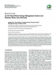
Fig. 1.
WBA network architecture
costs of such a wired backbone, WMNs are very cost-effective alternatives for enterprise networking. This last scenario is the starting point of the results presented in this paper. They arise from the research that was done in the scope of the IBBT Wireless Building Automation (WBA) project [7] which tackled the complex WBA problem dealing with a lot of trade offs. Sensors and actuators are battery powered and have to be as energy-efficient as possible, while the wireless network should also be perfomant enough to support large scale video surveillance. Critical building applications such as surveillance and fire detection require end-to-end Quality of Service to ensure the bandwidth and delay requirements also in the case of high network loads. Because no networking technology simultaneously fulfils all those requirements, a system architecture was developed that combines heterogeneous technologies into an appropriate networking solution. This architecture was presented in previous work [8] and consists of four different kinds of networks (figure 1): the Wired Backbone, the Wireless Mesh Network, the Wireless LAN and Sensor and Actuator networks (SANETs). In short, the Wired Backbone reuses the existing gigabit IP backbone, the Wireless LAN serves IEEE 802.11b/g devices such as PDA’s and wireless surveillance cameras and the SANET is responsible for transmitting monitor and control information as energy efficient as possible. The WMN is the heart of this architecture, interconnecting the other networks
and supporting their different QoS demands. The remainder of this paper will present the WMN that was developed in the WBA project. Section II will introduce the Ethernet based WMN. This is a distributed selforganizing, self-recovering and self-healing WMN. Section III discusses the Connection Management, a novel technique which combines application-level requirements into network path reservations and end device settings. In section IV the testbed will be described, and the results of the deployment in a historical building will be discussed. Finally, we conclude in section V. II. E THERNET BASED W IRELESS M ESH N ETWORK The requirements for the WBA WMN are the same as in most publications concerning mesh networks: tree-based architecture, automatic network configuration, distributed selfrecovery mechanisms and the possibility to adapt the routing to the conditions of the wireless medium. Most research defines WMNs from scratch, proposing their own architecture and routing protocols [1], [6], [10], or extends existing ad-hoc routing protocols [9]. In general, those solutions can always be situated on Layer 3 of the OSI Reference Model. Surprisingly almost no publications consider Switched Ethernet as base for the WMN. In previous work, we examined the capabilities of Switched Ethernet for building WMNs and revealed that it meets all the requirements [11]. Furthermore, it was shown that this Layer 2 solution enables very fast recovery by extending the standard spanning tree protocols, an indispensable property to support critical applications such as video surveillance and fire detection. Because of those promising results, the WBA WMN was designed as Wireless Ethernet, where the wired links are replaced by logical wireless communication links between nodes. Because the WMN nodes are fixed and do not have to be power efficient, standard IEEE 802.11 hardware was chosen as radio technology. More specific, the choice was made to operate in the IEEE 802.11a band, because there are more non-interfering channels (12 compared to 3 in b/g), and because there would be less interference with existing WLAN technology or other hardware such as wireless phones or micro wave ovens. Forwarding is performed using the address fields of the four address scheme of IEEE 802.11 frames, defining both the endto-end MAC addresses and the MAC addresses of the current link. This approach can also be found in the upcoming IEEE 802.11s standard regarding mesh networking [12]. Because our WMN architecture is a complete layer 2 solution, there is no need to utilize NAT or configure subnets on each WMN node to enable communication between end nodes. Instead, the WMN behaves as a standard wired Ethernet switch where all connected devices are in the same LAN. The architecture of a WMN node was partially presented in previous work [11]. The forwarding plane of the node consists of a standard VLAN aware Ethernet switch, together with the necessary Ethernet suppressors and Spanning Tree modules. Around this core the LinkProbe elements are responsible for
the fast detection of link failures. Finally, at the beginning and the end of the forwarding plane, the links (which are at this point not different from wired links) of the Ethernet switch are mapped to the corresponding wireless interface of the node, and to the correct link-level MAC addresses. On the incoming side, packets are received from a wireless interface and are put on the corresponding link of the Ethernet switch. This decision is based on the link-level MAC addresses used in the four address scheme. Then the WiFi headers are stripped from the packet, leaving only the end to end MAC addresses in an Ethernet header that can be used by the internal switch just as if it was connected through wired links. On the outgoing side, the inverse mapping is performed from link to wireless interfaces and correct MAC addresses and WiFi header. Besides the forwarding plane, the other elements are responsible for several distributed WMN optimizations which are discussed in the following subsections. A. Neighbour Interface binding (NIB) Two main tasks can be identified in the NIB process: coordinating the sequence in which the different nodes will try to set up links with their neighbours, and selecting appropriate neighbours and network interfaces for those links. Because the bottlenecks of a WMN can be found at the root, it is important that the nodes closest to the root can configure their links first. This results in more redundant links close to the root and thus increases possible throughputs. Because no node knows the complete network topology, he can never know for sure when it is his turn to bind. Therefore we will exchange a token between the WMN nodes. The algorithm of this approach is beyond the scope of this paper, but we can say that every node exactly knows when it is his turn to bind, using only the local neighbourhood information in every node. Another task of the NIB is the binding itself. A neighbour has to choose which neighbours that he wants to establish a link with, and on which network interface. A binding node will only select neighbours with the same or a higher rootdistance. When a binding node has chosen a neighbour, he has to choose on which interface he wants the link to be. That choice will be limited by the fact that we will always divide the available interfaces equally between up and down traffic. The reason for this division is the fact that we are focussing on an aggregation network where traffic will go from the root to leaves and back, meaning that in an intermediate node, what comes in must come out [17]. For a new link, the wireless interface with the lowest number of already established links will be chosen. This is to avoid the situation where e.g. three links use interface A and just one interface B, instead we want an equal division over available up or down interfaces to ensure load balancing over the wireless interfaces. If no other links already use that interface, it’s channel can be set on the same channel as the other interface of the link. If there is no free interface, then it has to be checked if no channel conflicts exist. Links between nodes on the same connectivity level are less important then up or down links. Therefore, links on the same connectivity level may only use a free interface.
B. Link Rate Adaption The physical layer of the IEEE 802.11 hardware used in the WMN provides multi-rate capabilities. To achieve a high performance under varying conditions, these devices need to adapt their transmission rate dynamically. Several techniques exist to determine the optimal rate for two wireless NICs to communicate [15]. We used the standard Click element MadwifiRate. This element starts with a low bit rate, and tries to raise the bitrate without introducing too many transmission errors. When stabilised, it will continuously monitor transmission status, and if a degradation of the wireless medium occurs, it will lower the bitrate settings. The MadwifiRate is able to set the bitrate on a per-packet base, making it possible to have links that use the same wireless NIC to operate on different bit rates. In previous work [11] we demonstrated how the output of this MadwifiRate algorithm can be used to adapt the Spanning Tree parameters. As a result, the WMN will automatically avoid poor wireless links, forwarding around obstacles and resulting in a higher overall network throughput. The other links are blocked, but can instantly be unblocked to perform a fast recovery after node failure. C. Recovery To provide fast recovery while maintaining the plug-andplay feature of Ethernet, the distributed Link Probe mechanism is used in cooperation with the RSTP protocol. The Link Probe Send module is placed on every link, behind the switch, and analysis the traffic on the switch. If there are no packets passing on that link within a certain time frame, it will inject a small link probe packet on the link. This ensures that there will be traffic within a certain time frame, without losing available bandwidth under load. On the other side of the link, before the ethernet switch, the Link Probe Analysis element checks if traffic passed within a certain window. If no packets passed, it is concluded that the link failed, and instantly the MSTP element is notified, which adjusts the spanning tree to maintain connectivity. This mechanism was previously introduced for wired Ethernet [16]. Research revealed that used with wireless Ethernet, link failure detection time is slightly higher, enabling detection times near 25 ms and recovery time of 30 ms [11]. To make the WMN self-healing, some extra functionality was added to the Link Probe Mechanism. If a link fails, it is blocked immediately, and if it receives traffic within the next few seconds, it instantly recovers. But if after that period of time there still is no traffic, the link is removed. This can release wireless interfaces which can then be used to establish new links with other neighbours. Therefore, an NIB token will be sent out, starting the NIB process and reoptimizing the network for the new situation. D. Channel Assignment A WMN suffers from throughput related problems such as excessive packet losses, unpredictable channel behaviours and throughput degradation. They are occasioned by intra-
and inter-flow interference [10], [18], [19]. When two data streams pass by each other, they will occupy the same wireless space and the same bandwidth which is called inter-flow interference. We can protect flows from inter-flow interference by separating them in the space dimension, keeping the two flows out of each others range, or in channel dimension, by selecting different channels on the links. Often data is sent multiple hops away. When sending data to the next hop it will interfere with the previous data, which is now sent by the next hop to another node. This is called intra-flow interference, in this case we cannot separate the flow in the space dimension thus we will need to change the channel every hop to reduce intra-flow interference. The NIB process mentioned above performs the initial channel assignment to guarantee that for every link, the two wireless interfaces are on the same channel. It is the task of the distributed Channel Assignment mechanisms to optimize that channel assignment to avoid intra- and inter-flow interference, keeping in mind that if one wireless interfaces changes it channel, then all the other wireless interfaces that have a link with that interface should also adopt that new channel. At certain times a node starts the algorithm to evaluate the local mesh information and decides to change one of its channels. The channel usage, which is the traffic on the channel, of the k-hop neighbourhood is used to determine whether a channel should be switched or not. This channel usage information is sent by k-neighbourhood beacons. When the node decides a channel should be changed, it starts up the change algorithm. This algorithm makes sure that all nodes that should change channel are informed, and they can block the change if necessary, for instance if there is another channel change going on within a 3-hop neighbourhood. The algorithm also coordinates the time of the simultaneous switch, and rolls back if there was any error. This way network oscillations are avoided, and no links can get lost due to channel switch problems.
E. Power Control Another technique to decrease inter-flow interference is to diminish transmission power to separate the flows in the space dimension. This is performed by the Power Control of the WMN. This mechanism will periodically try to lower the transmission power of the wireless interfaces as much as possible without introducing a quality loss on the links using that interface. This requires interaction with the rate control mechanisms described above in II-B. Once the rate control notices a drop in quality and would start to lower transmission rate, it notifies the Power Control which will return to the previous successful power level. As a result, the transmission power on each wireless interface is just high enough to maintain all of it’s links. It has to be mentioned that the power reduction has to be performed with care, keeping links at a decent bit-rate, minimizing the amount of retries and allowing margin for environment changes.
Fig. 2.
Basic function of Connection Management
F. Trigger The Channel Assignment and Power Control mentioned above all periodically try to optimize the network. On top of this functionality, a trigger element was added to the node architecture which continuously monitors the number of average transmission retries per packet on the MAC level. This information can be retrieved in Click from the Madwifi NG driver. Once this average exceeds a given threshold, the trigger instantly starts the Power Control and if still necessary the Channel Assignment to avoid link loss. III. C ONNECTION MANAGEMENT The extensive research that is conducted around the world regarding WMNs and throughput issues mostly tries to optimize the network for overall network throughput, assuming that the traffic characteristics are roughly equal for all end nodes. This is a correct assumption for some scenarios, e.g. Internet connectivity to all the end clients. But this is not the case for wireless video surveillance needed in wireless building automation or emergency response in disaster areas. Under normal surveillance conditions, a video wall will show a large number of low quality video at the same time, requiring an equal limited bandwidth between different cameras and the control room where the video wall is placed. This scenario could be supported by the several implemented WMN testbeds or products available today. However, under critical conditions, e.g. when a fire alarm was triggered, or the operator notices an emergency on one of the screens of the video wall, the operator needs high quality video from the different cameras in the proximity of the incident. This enables him to instantly evaluate the situation and react appropriately, saving valuable time. Because the cameras are in each others vicinity and the video streams all have to go the same control room, the different streams will follow the same path through the WMN. This means that the capacity of that path (defined by its weakest link) severely restricts the amount of critical video streams that can be viewed in emergency situations.
This problematic use case led to the development of our Connection Management. The main idea is that if the normal path is congested, the network should try to use less loaded parts of the network to forward additional video streams. The Connection Management receives bandwidth requests from the applications (supporting all kind of applications, not only video), and uses a real-time view of the network topology and link capacities to calculate the best path for that connection. On this path, the demanded bandwidth is reserved for the lifetime of the connection. This means that the first connections will be reserved over the shortest path, and when this is congested, other request will be routed along other paths through the network. This is depicted in figure 2 where two streams are requested between A and C, for 5 and 6 Mbit. Because the direct link between A and C has a capacity of 10, the first stream is forwarded via this link. But the second stream needs another 6, meaning that if the stream was forwarded over the same path, the link would be loaded with 11 Mbit, which is too much. Therefore, the Connection Management ensures that the second stream will be forwarded from A to B to C, enabling the streaming of both video sources from A to C. As a result, the network is able to adjust to dynamically changing traffic demands of the applications, guaranteeing the demanded bandwidth, and supporting a higher possible throughput between two WMN end points. It is obvious that these characteristics do not only benefit the video surveillance use case, but can be useful in many other applications. Similar traffic engineering techniques exist today (MPLS, RSVP), but they are mainly deployed in specialised network cores such as ISP backbones. The introduction of traffic engineering in the field of Wireless Mesh Networks as presented in this paper is a novel idea with promising possibilities in scenarios with dynamic traffic demands. The Connection Management was implemented on top of the Ethernet based WMN described in the previous section. This means that the WMN can work perfectly without it, offering best effort services to all end devices. When the network has to support scenarios as described above, it is sufficient to add a server with the Connection Management. For the implementation of the management, three building blocks are necessary. The first one is a correct central realtime view of the network topology, and an accurate estimation of the bandwidth capacity of every link. The second one is a central software module that can calculate the path and possible bandwidth for a connection request. The third one is a mechanism to ensure that a connection does not consume more bandwidth then it has been assigned. A. Bandwidth Estimation To ensure the real-time topology view of the network, all the mesh nodes will send a status message to the Connection Management when they come online, when they establish a new link, when a link failure is detected, etc. The nodes also periodically estimate the bandwidth capacity of their links which they send to the management. This capacity informa-
Fig. 3.
Best path calculation
tion is crucial for the Connection Management to function correctly. When estimating too low, a part of the network capacity will remain unused, while estimating too high can result in network congestion, the exact phenomenon that the Connection Management should resolve. These problems demonstrate the utter importance of an accurate bandwidth estimation algorithm. In wireless networks, the available bandwidth undergoes fast time-scale variations due to channel fading and error from physical obstacles. These effects are not present in wireline networks, and make estimation of available bandwidth in wireless networks a challenging task. Furthermore, the wireless channel is also a shared-access medium, and the available bandwidth also varies with the number of hosts contending for the channel. For this problem several solutions have been proposed, based on different techniques such as variable packet size probing, packet-pair probing, etc [20], [21]. In our WMN, we implemented the technique presented in [22]. This scheme does not modify the CSMA/CA MAC protocol in any manner, but gauges the effect of phenomena such as medium contention, channel fading and interference, which influence the available bandwidth. Based on the effect of those phenomena on the working of the medium-access scheme, the available bandwidth is estimated of a wireless host to each of its neighbours. B. Path reservation The central software component of our Connection Management was written in Java. It represents the network as a weighted graph on which standard algorithms can be used. The weights on the edges represent the capacities on the links. For this representation we used TRS, a Telecom Research Software platform developed in our IBCN-group [23]. When a request is received by the Connection Management, it has to calculate the best path for that connection. As depicted on the left of figure 3, this is not always the shortest path between the two end points. A connection of 6 megabit is requested between A and B, but the shortest path, the direct link between A and B, does not offer sufficient bandwidth. Instead, the widest path (the path with the highest capacities on its links) can offer sufficient bandwidth, but it may take a longer route then necessary, introducing unnecessary delay. On the figure, the widest path is A-B-C-D. The path that we
would want to use is A-C-B, the shortest path that is just wide enough for the requested bandwidth. To calculate this path, we make a small adjustment to the graph which allows us to use the standard Dijkstra algorithm for shortest path calculation. When a connection is received for a certain bandwidth, the costs of the edges of the graph are temporarily changed: every edge that has enough free capacity (= total capacity - already reserved capacity for other connections) to support the requested bandwidth gets cost 1, all the other edges receive a cost of positive infinity (right side of figure 3). Then we use Dijkstra, and if the total cost of the resulting path is smaller then infinity, we have found the shortest path that is just wide enough. If the cost was infinity, the bandwidth can not be supported by the network. In that case we iterate this calculation with smaller requested bandwidth values until we find the maximum value that can be supported. This value is fed back to the application that requested the connection. To actually execute the reserved connection, every node on the path of the connection receives a control message from the Connection Management indicating the connection id (an unique integer larger then a certain threshold idMin), and which of his links are included in the reservation. On the wired port (where the source packets will enter the WMN) of each mesh node a Click element analysis incoming packets, and if the source and destinations IP addresses and ports match a known connection, the connection id is inserted in the VLAN header of the packet. Otherwise the VLAN header is set to 1. From then on, all the nodes in the WMN can forward the packet by just analysing the VLAN number. If it is 1, normal Ethernet forwarding is performed following the spanning tree, but when it is larger then idMin, it will forward the packet using the path information in his connection reservation table. The Ethernet suppressors were also adjusted to never block packets with a VLAN header > idMin. Otherwise it would be impossible to deviate from the spanning tree. Typically, an application will request a connection between two clients which are connected to WMN nodes, and not between the WMN nodes itself. But the Connection Management performs reservations between WMN nodes. To map client IP addresses to mesh nodes, an element was added to the wired port of every node which analyses passing ARP requests, learns which are the IP addresses connected, and sends this information to the Connection Management. C. Rate Control To ensure the correct operation of the Connection Management, it is necessary that no connection consumes more bandwidth then it has been given. To ensure this in the WBA video surveillance scenario, we used intelligent video encoders on the cameras on which the bitrate of the outcoming video stream can be adjusted. In [6] an adaptive-rate video source was already proposed for video surveillance over a WMN, but this solution chooses the encoding parameters according the number of packets waiting in a transmission buffer. This will avoid network congestion, but still suffers from the problem
that our Connection Management resolves, it cannot adjust to the dynamically changing traffic demands of the video application. In the WBA project, an existing video surveillance application of an industrial partner was adjusted to interact with the Connection Management. When the user demands a video stream, the application contacts the Connection Management, which will return the received bandwidth. The video application forwards this bitrate to the encoders which adjust their encoding settings to comply with the bandwidth restriction. Then finally the video stream will be started and displayed in the application.
reader is built in on the front of the enclosure. This enables fast software updating by copying to CF if the testbed nodes are not connected to a network. The four wireless interfaces were Wistron CM9 miniPCI a/b/g cards. These four cards were installed in a RouterBoard 14 card which allows four miniPCI cards to be connected to a single PCI slot. This card was plugged into the single PCI slot of the motherboard. It has to be mentioned that for this combination to work, the madwifi driver has to be loaded with the rfkill=0 option. Finally, four holes were drilled in the M300 enclosure to install the antennas for the wireless interfaces.
IV. D EPLOYED TESTBED
At the end of the project, the testbed was deployed for testing and demo purposes in Arts Centre Vooruit [25], a historical building serving as a realistic test environment. Eight nodes were installed across a dance studio on the third floor and a large theatre hall and foyer on the fourth floor. To avoid interference by people, the nodes were placed on top of wooden columns with a height of 2.44 meters. Several PCs, eight cameras, a WLAN access point, a tablet PC and two SANET gateways where then connected to the WMN as the final WBA demonstrator setup.
We implemented the distributed WMN software in C++ on the Click Modular Router platform [13], a Linux open source platform for the development of software routers. Together with the Madwifi NG driver for the wireless interfaces, this allowed us to send and receive packets in raw format, enabling us to adjust WiFi MAC headers, retrieve important MAC statistics concerning packets, etc. The modular design of Click also allowed us to reuse some existing elements, enabling faster prototyping. Because Click can easily be coupled to the NS-2 network simulator [14], we were also able to use the same code both in simulations and real life testing, drastically lowering development time. The central Connection Management was written in Java and deployed on a J2EE5 backbone. Interaction with the video application was implemented via web services. The graphical user interface of the Connection Management was a standard Java application, interacting with the application server, providing a view of both the network status and the requested connections. It also allowed us to set up, edit or tear down connections for other applications that were not extended to interact automatically with the Connection Management. A. Testbed equipment The distributed software was initially deployed on three Linux PCs with an AMD Athlon 64 3ghz processor and 1024 MB of RAM. On every node there were two D-Link wireless NICs with Atheros AR5212 chipset (IEEE 802.11 a/b/g compliant), steered by the Madwifi NG driver. The wireless interfaces were connected to external antennas that could be separated a few feet. The PCs used the 2.6.16.13 Linux kernel, patched with the Click patch to run Click in the more performant kernel mode. Then we switched to a small form factor testbed which would be more realistic in a real life deployment. It was based on a Jetway J7F4K mini-ITX motherboard with a 1.2 Ghz VIA C7 EDEN processor. This had the advantage that it is a small form factor motherboard (17cm x 17cm), it is fully intel x86 compatible keeping software development much simpler, it is quiet (completely fanless) and it is powerful. It was equipped with 512 MB RAM, and installed in a MiniBox M300-LCD enclosure. This enclosure has the benefit that it can use a Compact Flash card as hard drive, and a CF
B. Deployment location
C. Lessons learned One of the big differences between our work and most other WMN research is the fact that we actually implemented a testbed and deployed it in a realistic location. Among the many papers that tackle WMN related problems, only a few can be found that actually implemented an entire WMN [1], [26], [27]. The extensive testing we performed on location in preparation of the final demonstrator of the WBA project revealed a few issues. A first problem that we encountered is the fact that neighbours with very bad links can cause severe network instabilities, even in the initial network configuration phase, a problem that has been identified before [5]. This is caused by the very high percentage of packet loss between the node and the distant neighbour. Therefore we advise that when building neighbourhood information, a metric is used to decide which neighbours may be included in the neighbourhood. Another lesson learned is the importance of the rate control mechanism described in II-B. Initially we had some bugs in this element, which were only revealed in the much harsher real-life environment. Because the rate control did not function properly, bit rates were too high, resulting in a high degree of packet loss and severe network instabilities. This was not the case in our initial lab setup where all nodes were placed close to each other in the same room, but made the WMN practically unusable in real-life. Therefore we recommend that in every WMN design, to increase network stability, mechanisms are included that make sure that the bitrate of the interfaces is never too high. We also noticed that because the nodes were placed 2.44 m above the ground, the WMN was very stable on a single floor, even when during the final demonstration 140 people
were present. But when going from one floor to the other, even a few people standing in the radio link could heavily disrupt connectivity. Therefore multi-floor WMN connectivity is a research challenge that should be further studied. The last and most important issue is the fact that you need a careful hardware design when using multiple interfaces, especially with four wireless interfaces per node. During installation we noticed severe bandwidth drops when multihopping, starvation of one interface over the other, a total bandwidth that does not exceed that of one interface, etc. These problems have already been studied in literature [28], [29], and it is concluded that in a multiple interface node the interfaces should be extensively shielded, and that the antennas should be placed far enough (up to 1 m) from each other. We also noticed that node placement was very sensitive. A node could have a very bad link with a neighbour, but moving the node a few centimetres resulted in an almost perfect link. This problem could be resolved by using antenna diversity, utilising two antennas per wireless interface. Although all these problems are not new in literature, we would like to emphasize that a WMN testbed has to be based on a solid hardware platform, otherwise the testbed will always be unstable and the measured results will never be a valid representation of the actual capabilities of the developed network. A well designed reference hardware platform that can be used for all WMN research worldwide could prove to be an essential tool in future WMN development. V. C ONCLUSION In this paper we introduced an Ethernet based Wireless Mesh Network. Because it is self-organizing, self-recovering and self-healing, Ethernet proved to be a very suitable WMN technology. To replace the wired links we added converter elements to a standard Ethernet switch, together with the distributed functionality to automatically configure those links. To enable fast link failure detection and recovery, we used a Link Probe mechanism that was previously used in wired Ethernet and proved to be just as useful in a wireless environment. To optimize the WMN performance, we adjusted the forwarding to the conditions of the wireless medium to induce usage of the best links. We also implemented a distributed Channel Assignment that optimizes the WMN according to the traffic load on the network, and Power Control that diminishes interflow interference. On top of this network, we introduced the novel concept of Connection Management, bringing traffic engineering techniques to the WMN domain for the first time. As a result, the network is able to adjust to dynamically changing traffic demands of the applications, guaranteeing them the demanded bandwidth, and supporting a much higher possible throughput between two end points. In contradiction with most other WMN research, we implemented all the discussed solutions, running both in simulations and on a real testbed deployed in a real-life environment. Observed network behaviour demonstrated the necessity for a well designed reference hardware platform that can be used for WMN research.
ACKNOWLEDGMENT This research was funded by the IBBT WBA project [7]. R EFERENCES [1] A. Raniwala and T. Chiueh; “Architecture and Algorithms for an IEEE 802.11-Based Multi-Channel Wireless Mesh Network”, Proceedings of IEEE Infocom 2005 [2] One Laptop Per Child 802.11s Implementation, http://wiki.laptop.org/ go/802.11s Connectivity Test Plan [3] MIT Roofnet, http://pdos.csail.mit.edu/roofnet/doku.php [4] Champaign-Urbana Community Wireless Network, www.cuwin.net [5] B. Braunstein, T. Trimble, R. Mishra, B.S. Manoj and R.Rao; “On the Traffic Behavior of Distributed Wireless Mesh Networks”, Proceedings of IEEE WoWMoM 2006 [6] F. Licandro, A. Lombardo and G. Schembra; “Applying Multipath Routing to a Video Surveillance System Deployed over a Wireless Mesh Network, Proceedings of ACM WMuNeP 2006 [7] Wireless Building Automation, https://wba.ibbt.be [8] W. Vandenberghe, B. Latr´e, F. De Greve et al; “A System Architecture for Wireless Building Automation”, Proc. of IST Mobile Summit 2006 [9] A.A. Pirzada, M. Portmann and J. Indulska; “Evaluation of Multi-Radio Extensions to AODV for Wireless Mesh Networks”, Proceedings of ACM MobiWac 2006 [10] H. Lim, C. Lim and J.C. Hou; “A Coordinate-Based approach for Exploiting Temoral-Spatial Diversity in Wireless Mesh Networks”, Proceedings of ACM MobiCom 2006 [11] F. De Greve, W. Vandenberghe, F. De Turck, I. Moerman and P. Demeester; “Towards Ethernet-based wireless mesh networks for fast moving users”, Proceedings of IEEE EUROMICRO 2006 [12] G.R. Hiertz, S. Max, E. Weiss et al; “Mesh Technology enabling Ubiquitous Wireless Networks”, Proceedings of ICST WICON 2006 [13] The Click Modular Router project, http://read.cs.ucla.edu/click/ [14] The network simulator ns-2, http://www.isi.edu/nsnam/ns/ [15] M. Lacage, M.H. Manshaei and T. Turletti; “IEEE 802.11 Rate Adaption : A Practical Approach”, Proceedings of ACM MSWiM 2004 [16] F. De Greve, F. Van Quickenborne et al; “A new carrier-grade aggregation network model for delivering broadband service to fast moving users”, International Journal of Communication Systems, Volume 20, issue 3 (March 2007), p 335-364 [17] F. De Greve, F. De Turck, I. Moerman and P. Demeester;“Design of Wireless Mesh Networks for Aggregating Traffic of Fast Moving Users”, Proceedings of ACM MobiWAC 2006 [18] Z. Fu, H. Luo, P. Zerfos, S. Lu, L. Zhang and M. Gerla; “The impact of multihop wireless channel on TCP performance”, IEEE Trans. on Mobile Computing, 4(2):209-221, March/April 2005 [19] K. Sanzgiri, I.D. Chakeres and E.M. Belding-Royer; “Determining intraflow contention along multihop paths in wireless networks”, Proceedings of Broadnets Wireless Networking Symposium, October 2004 [20] R.S. Prasad, M. Murray, C. Dovrolis, K. Claffy; “Bandwidth Estimation: metrics, measurement techniques, and tools”, IEEE network, NovemberDecember 2003 [21] T. Sun, G. Yang, L. Chen, M.Y. Sanadidi, M. Gerla; “A Measurement Study of Path Capacity in 802.11b based Wireless Networks”, Proceedings of WitMeMo 2005 [22] S.H. Shah, K. Chen, K. Nahrstedt; “Available Bandwidth Estimation in IEEE 802.11-based Wireless Networks”, Proc. of ISMA BEst 2003 [23] Telecom Research Software, http://www.ibcn.intec.ugent.be/ INTERNAL/TRS/member/index.html [24] Madwifi Multiband Atheros driver for WiFi, http://madwifi.org/ [25] Kunstencentrum Vooruit, http://www.vooruit.be/nl/gebouw [26] S.M. Das, H. Pucha, D. Koutsonikolas, Y.C. Hu and D. Peroulis; “DMesh: Incorporating Practical Directional Antennas in Multichannel Wireless Mesh Networks”, IEEE Journal on selected areas in communications, vol 24, no 11, november 2006 [27] L. Lannone, k. Kabassanov, S. Fdida; “The Real Gain of Cross-Layer Routing in Wireless Mesh Networks”, Proc. of ACM REALMAN 2006 [28] J. Robinson, K. Papagiannaki, C. Diot, X. Guo and L. Krishnamurthy; “Experimenting with a Multi-Radio Mesh Networking Testbed”, Proceedings of WiNMee 2005 [29] C. Cheng, P. Hsiao, H.T. Kung and D. Vlah; “Adjacent Channel Interference in Dual-radio 802.11a Nodes and Its Impact on Multi-hop Networking”; Proceedings of IEEE Globecom 2006