Proceedings of the 33rd Hawaii International Conference on System Sciences - 2000
Connector-oriented Workflow System for the Support of Structured Ad hoc Workflow Dongsoo Han, Jaeyong Shim School of Engineering , Information and Communications University P.0.Box 77 Yusong P.O., Taejon, 305-600 Korea e-mail :
[email protected] ,
[email protected] phone : 82-42-866-6130 Abstract
events happen frequently during the processing, it is not always possible to define precisely all the processes in advance. Thus, the conventional workflow paradigm in which processes are defined in advance [1,2,6,8] is not suited well to the situation. In a conventional workflow system, such processes are classified as ad hoc workflow and the support for the processes by the workflow system [9, 10,20] is passive and limited. However many activities in an office environment form sequences under some rules even without the workflow concept. Such sequences seem to be incomplete and disconnected at a glance, but they are often connected based on some rules to achieve a certain goal. We define this workflow as structured ad hoc workflow to differentiate it from inherently ad hoc workflow where no patterns can be derived from the activities in the workflow. The delivery of work items in structured ad hoc workflow is similar to that in inherently ad hoc workflow [9, 15, 25]. But when a structured ad hoc workflow instance is completed, a flow can be derived and the derived flow can be shared by other workflow instances of the same workflow class because the same rules are applied to the workflow instances in the same workflow class. Note that workflow instances in the same workflow class of structured ad hoc workflow need not exactly be the same. Rather, they share some parts that are the same as each other. Therefore in structured ad hoc workflow some part of the predefined process template can be reused while the predefined workflow template rarely can be reused in inherently ad hoc workflow. Structured ad hoc workflow differs from production or administrative workflow in that only part of the workflow template can be reused in structured ad hoc workflow while in production or administrative workflow[19, 21], the whole workflow template is defined and used to generate workflow instances. Although the structured ad hoc workflow differs from administrative and production workflow, the benefit of structured ad hoc workflow automation should not be underestimated. Almost the same or even more benefits can be obtained from structured ad hoc workflow
In large scale enterprises composed of more than several hundred departments, many workflows still remain in non-automated state which is a serious burden to the enterprises. Usually workflow of a large scale enterprise is in the mixed form of multiple types of workflow where ad hoc workflow is the major hurdle for the automation. While conventional workflow systems support well a certain type of workflow, it does not get along with mixed type of workflow. In this paper we classified ad hoc workflow into structured and inherently ad hoc workflow and proposed a workflow system equipped with connector facility to support structured ad hoc workflow such as decision approval process. The connector facility can be regarded as semi-workflow system to support structured ad hoc workflow effectively or it can be a subsidiary facility for a workflow system to enforce the support of the structured ad hoc workflow in the base workflow system. We are implementing it in Hanuri/TFlow, our distributed transactional workflow system and the details of the connector-oriented extensions to the system are described in this paper.
1. Preface With the proliferation of workflow systems, the inclination to apply workflow system to general office business processes is gradually spreading. Conventional workflow systems aim to raise productivity by processing tasks along well-predefined paths. If the business process can be defined in advance, the overhead of delivering work items between tasks can be diminished and the work item misdelivery rate can be reduced with the help of workflow system [23]. Moreover, parallel tasks can be performed concurrently in the workflow system. For an organization to fully achieve these benefits with the workflow system, predefined workflow that is defined at build time is not changed frequently and the defined workflow iterates over and over [24,27]. However, in an office environment where unexpected
1/9 0-7695-0493-0/00 $10.00 (c) 2000 IEEE
1
Proceedings of the 33rd Hawaii International Conference on System Sciences - 2000
we explain the concept and usage of the connector facility in a workflow system. In section 4, we describe Hanuri/TFlow system and the extension of the system to accommodate the connector facility. In section 5, we show how an example workflow can be implemented in the connector-oriented workflow system. We discuss conclusion in section 6.
automation than those from administrative and production workflow automations. More flexible concepts and facilities have to be introduced for a workflow system to support structured ad hoc workflow effectively. Conventional workflow systems separates workflow build time and run time rather clearly and emphasizes the advantage of the separation because the separation frees the workflow designers from the details of the workflow implementation [1]. Meanwhile run-time process definition or modification, which is treated as a special event in conventional workflow system, is frequent in structured ad hoc workflow. Although run-time process definition can be accommodated to some degree by dynamic workflow reconfiguration, more functions and facilities should be provided for the complete support of structured ad hoc workflow. For a workflow system to support structured ad hoc workflow, run-time process definition should be regarded as a normal process. Hence the following functions should be provided. First, workflow fragments defined at run time are integrated to form a whole workflow. Second, the workflows of automated and manual departments are connected seamlessly. Third, a workflow fragment definition function is provided. Fourth, a workflow fragment template managing facility is provided. In this paper we propose a connector-oriented workflow system(COWS) to support structured ad hoc workflow. Connector-oriented workflow provides the aforementioned functions using the connector facility. We devised the connector facility based on the observation that the key for the connection between departments when delivering work items is the inbox of the department. The connector facility can be regarded as a semi-workflow system including the role of inbox of a department. The connector facility manages workflow fragments generated at run time between connectors and provides many advantages in supporting structured ad hoc workflow. The followings are the benefits of a connector-oriented workflow system: - easy connection of well-defined workflow and partlydefined workflow - incremental workflow refinement support - black box workflow module connection - adaptive workflow implementation - interactive process definition support - easy connection of other application system through connector We showed that the connector-oriented workflow system can be implemented easily by adding the connector facility to our Hanuri/TFlow of distributed transactional workflow system. The paper is organized as follows. In section 2, we describe the workflow paradigm shift which is the motivation of this study. In section 3,
2. Workflow Paradigm Shift In the traditional workflow paradigm, a process template is designed at process build time and then the defined workflow is processed along the defined paths with the help of the workflow system. This workflow paradigm could be effective in an organization whose scale is relatively small and the business process can be derived easily prior to execution of workflow. Furthermore when the defined processes are rarely changed, business process automation is much more effective. However, in large scale enterprises, the business process derivation is usually not so simple and the defined processes are liable to be changed frequently [18]. Also, automated and manual departments are often coexist. Conventional workflow paradigm and workflow systems are not proper to automate business processes in such an environment. In a large enterprise, many business processes that seem to be disconnected are actually connected based on some rules or practices. To automate business processes that seem to be disconnected, workflow participants should be able to define workflow fragments at run time easily and the workflow system should be able to manage
BPR
BPR
3
1 Workflow Process Design 2 Implementation & Management Traditional Approach
3
Workflow Process Design
4
2
Workflow Process Design
1
Implementation & Management New Approach
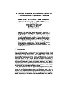
Figure 1. Traditional Workflow Paradigm and New Workflow Paradigm
2/9 0-7695-0493-0/00 $10.00 (c) 2000 IEEE
2
Proceedings of the 33rd Hawaii International Conference on System Sciences - 2000
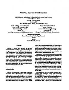
work items, for the same workflow instances to be connected it keeps the workflow instance ID and propagates it until the process instance is completed. Second, the connector has to provide some means to access the data it stores. For that it provides APIs(Application Program Interface) for application programs or user interfaces for users. Third, the connector has functions to register events and keep statistical information on historical events. This information not only shows the current situation but also can be used as basic data for extracting the execution path to enable BPR(Business Process Reengineering). Fourth, the connector provides facility to define structured data easily. The defined structured data for each connector are manipulated and managed by the workflow system in integrated manner. Although the way of structured data managing is similar to that of workflow relevant data, it differs from the workflow relevant data in that it can be defined at run time. Fifth, the connector has a function to keep the workflow fragments defined at run time and provides some facilities to reuse the workflow fragments easily. Using this facility, the whole workflow can be built from the defined workflow fragments in an incremental way. Figure 2 shows the layered view of the connector facility.
and integrate these workflow fragments. Later, the workflow system can derive the whole workflow automatically or it can provide defined process information to the workflow designer. This approach can be applied to design the complete workflow from workflow fragments incrementally. Figure 1 compares the traditional workflow paradigm with the new workflow paradigm. The fundamental difference between the two paradigms is in the starting point of each paradigm. In new workflow paradigm, business processes can be automated without predefined workflow process, while in the conventional approach business process should be defined prior to the execution of the workflow. Which can make big differences when the workflow system is deployed to a company because the preliminary steps to automate a workflow in new approach are much shorter than those in conventional approach. However in new approach, manual and automated departments inevitably coexist for some time until the whole workflow is automated. For a workflow system to support incremental workflow development, it should provide special facilities to accommodate partly automated workflow. Since manual and automated department can coexist in the early stage of workflow development, the facility should be able to connect both departments. The connector provides a means to connect the workflow of an automated department with that of a manual department. Workers in the manual department draw work items from the connector of the department and the processed work items are delivered to the connector of the next department. The owner department of the connector does not take into account whether the work items come from a manual department or an automated department. In this way, the workflow of the manual and automated departments can be connected seamlessly. Therefore the connector facility can be used not to define the whole process of a large organization once and forever, but rather to define parts of a process incrementally and derive the whole workflow as a culminating step.
3.1. Workflow definition in COWS In a connector-oriented workflow system, workflow either can be defined at workflow build time like conventional workflow system or a fragment of workflow can be defined at run time. The defined workflow fragments are stored to some place in the form of workflow templates so that they can be exploited for the next workflow definition. The frequency of usage of the
Interface Layer
3. Connector Facility
Service Layer
A connector is defined as a storage and services either to store incoming work items or data from the other departments or to access the storage. With the dynamic reconfiguration facility, a connector facility plays a key role to support ad hoc workflow. The main function of the connector is to connect inter-department workflow with the following functions. First, the connector has a storage service to store the work items to be handed over from several departments to one department. When it stores the
Monitoring
History Analysis Service
Storage Layer
History Storage
User InBox
History Data Collection Service
Organ. Resource Storage
Process
Structured
Builder
Data Design
Organ. Resource Access Service
Document Storage
Document/ Process Template/ Structured Data Managing Service
Process Template Storage
Application Program
Structured Data Access Service
Structured Data Storage
Figure 2. Layered View of the Connector Facility
3/9 0-7695-0493-0/00 $10.00 (c) 2000 IEEE
3
Proceedings of the 33rd Hawaii International Conference on System Sciences - 2000
typical workflow processing mechanism for a decision approval support system that is very popular in several oriental countries.
workflow template is registered as basic data for BPR. The last node of the workflow fragments defined at run time should be either the end node of the whole workflow or a connector to the department to which the work item has to be passed. One or more connectors could be connected as the last nodes of a workflow fragment. For the definition of the workflow fragment of a department, both activity-oriented workflow definition and actor-oriented workflow definition are supported. In activity-oriented workflow definition, which is the standard workflow definition method, workflow is composed of connected activities that have their own attributes respectively. Therefore, in activity-oriented workflow definition, the activity derivation is inevitable and the naming of the activity should be entailed. To the run time definer of the simple transient workflow fragment, the activity derivation and naming process could be cumbersome chores. In actor-oriented workflow definition, the definer only lists the actors that the work items should be handed over. Although the actor-oriented workflow definition has some constraint in defining workflow, it is useful for the non-expert workflow designer to define simple workflow path dynamically. Actually the actor-oriented process definition is adopted and well suited to the decision approval support system. The decision approval path can be determined at run time by designating nodes in the path in the name of actors or roles. In a connector-oriented workflow system, structured data can be defined at run time similarly to the workflow relevant data definition in a standard workflow system. Once the data are defined they are treated equivalently to the workflow relevant data defined at build time.
3.3. Coupling of automatic and manual workflow in COWS Work item delivery between automatic and manual departments can be performed using the e-mail system. We assume that even though the manual department processes the workflow manually it also has a connector to receive work items from the other departments. The work item processed in the manual department is handed over to the other department through the e-mail system. One problem in delivering the work item through the email system is that there is no pertinent means to deliver structured data from one department to another. Although the structured data can be attached to the work item, it cannot be accessed directly from the application unless they are registered as structured data to the connector in the department. Since the system provides the means to register the structured data to the connector, small scale structured data can be registered manually. For the large scale structured data automatic registering program needs to be developed.
4. Implementation We implemented the connector facility in Hanuri/TFlow workflow system which is a distributed transactional workflow system designed to support multitype workflow [12]. In this section we introduce Hanuri/TFlow system and the extension of the system to accommodate the connector facility.
3.2. Workflow processing in COWS 4.1. Hanuri/TFlow System Workflow processing in a department is started by keeping a work item from the connector of the department. The work items received from the preceding departments are cumulated in its connector. The work items in the connector either can be fetched by the corresponding actor directly or forwarded to the corresponding actors by the connector manager. Generally, at least one connector manager is assigned to the connector of a department. When the corresponding actor can be decided by the system, the delivery service can be done automatically by the system. Once a work item is delivered to the corresponding actor, he selects the appropriate workflow template from the workflow template storage and starts the workflow. If there is no appropriate workflow template, he creates a new workflow template and registers the newly defined workflow template before starting the workflow. This is a
USER INTERFACE
Process Builder Simulator
Admin/ Monitoring Service
TMIs & GTMIs
Worklist Handler
TMIF/GTMIG WTS ( Workflow Transaction Service )
CORBA ( O R B )
Figure 3. System Architecture of Hanuri/TFlow
4/9 0-7695-0493-0/00 $10.00 (c) 2000 IEEE
4
Proceedings of the 33rd Hawaii International Conference on System Sciences - 2000
by the user directives or considering the system configuration as described in the subsection 4.1.4. When one server is down, the GTMI searches an alternative server and uses the selected server on behalf of the crashed server. In this way, the whole system can maintain high system availability irrespective of system failures.
This section describes the system architecture and the components of Hanuri/TFlow system in which the connector facility is implemented. Hanuri/TFlow system is developed on the CORBA environment using WTS(Workflow Transaction Services) which is specially devised for Hanuri/TFlow system. The WTS can be considered as a kind of extension of CORBA OTS(Object Transaction Service) to enable convenient workflow system development on it. Details about the WTS specifications will be treated in other papers in the near future. The components of Hanuri/TFlow system include TMIF(Task Managing Instance Factory), GTMIG(Global Task Managing Instance Generator), Simulator, Process Builder, Admin/Monitoring Service, and Worklist Handler. Every component is built as CORBA objects and the details of each module will be described in the following subsections. Figure 3 shows the system architecture of Hanuri/TFlow system.
4.1.3. A Workflow Instance Life Cycle. In this subsection, we explain what is happening in Hanuri/TFlow system when a process instance creation is requested by a user. The following is the normal sequence of the steps from a process instance creation to the end of its execution: 1. 2. 3.
4.1.1. TMI and GTMI. TMI(Task Managing Instance) is created for each activity to manage the task of the activity. It either sends a work item to a worklist handler or invokes an application through the application agents. Application agents access the workflow relevant data via TMI. The TMI also monitors the status of the invoked tasks by communication with worklist handlers or application agents. When a task is completed the TMI sends the start event to the next TMI and the TMI which receives the event starts the task. In this way, control is transmitted as defined at process build time. GTMI controls the processing of the global process instance. It either receives status reports from the TMIs or suspends TMIs transiently to handle requests from the administrator such as dynamic reconfiguration. Although a TMI has to report its status to its GTMI, TMI can continue its execution even if the GTMI crashes because it does not check whether the GTMI has received its report or not. This approach is effective to achieve availability in a distributed environment where network partitioning is frequent.
4. 5. 6. 7. 8.
A user asks to create a certain process instance GTMIG creates a GTMI for the process instance through TMIF GTMI creates all TMIs of the process instance through TMIF GTMI sends a start signal to the first TMI to start work TMI starts work and sends a start signal to the next TMI once the work is finished successfully. Iterate step 5 until the last TMI is reached The last TMI sends an end signal to the GTMI when it finishes GTMI destroys all the TMIs generated and itself
Both GTMIG and TMIF are resident in all the servers. Therefore if one server crashes the other server can take over the GTMI and TMI creation job instead. When GTMI creates TMIs, it can place the TMIs in several different ways based on the user directives. A user can denote which TMI should be placed on which server explicitly when defining a process template. If there are no user directives at all, TMIs are created in a distributed Workflow Server Workflow Server GTMIG GTMIG TMIF
4.1.2. GTMIG and TMIFs. Each server is equipped with one GTMIG and one or more TMIFs respectively. GTMIG asks TMIF to generate a GTMI for a process instance and the GTMI asks TMIF to generate all the TMIs for the process instance. Since multiple TMIs are generated and the TMIs may be created on different servers, when GTMI asks TMIF to generate TMIs, it asks the TMIF that is resident on the same site as the generated TMIs. To the GTMI, local TMIFs and remote TMIFs are viewed equivalently and they are invoked in the same way. So the workflow system operates in a fully distributed fashion. The TMI generation site is determined
GTMI
O R B
O R B
TMIF GTMI
TMI CORBA
DB
...
CORBA
ORB
TMI ...
DB
WL handler WL handler
CORBA IIOP
Activity status
Workflow Server GTMIG TMIF GTMI
TMI CORBA
DB
...
application O R B
Application Status ready running
WL handler fail success
Figure 4. Run Time Architecture of Hanuri/TFlow System
5/9 0-7695-0493-0/00 $10.00 (c) 2000 IEEE
5
Proceedings of the 33rd Hawaii International Conference on System Sciences - 2000
TMI
Worklist Handler
Client
TMI
……
Worklist Handler
Client
TMI
……
……
be connected to any worklist handler to send work items to clients and a client can be connected to any worklist handler to receive work items. Several worklist handlers can retain different worklists for a client but the worklists for a client are usually maintained by the primary worklist handler. Figure 5 shows the conceptual view of these connections. Since the addition of a new worklist handler to the system can be achieved by a slight change of a database and the crash of a worklist handler does not imply disconnection of the TMI from the client, the system is very scalable and resilient. In the following sections, we describe the functions of each component in more detail.
Worklist Handler
Client
4.2. Features to Support Ad hoc Workflow
Figure 5. C once ptu al V iew of C onnection am on g TMIs, Worklist Handlers, and Clients
In this subsection, we describe some features for a workflow system to support ad hoc workflow. Firstly, as ad hoc workflow frequently changes its path during the execution, for a workflow system to support ad hoc workflow, it should be equipped with dynamic reconfiguration facilities[9]. Secondly, ad hoc workflow requires some facilities that can connect the activity steps and hand over the work items through the facilities. In a manual ad hoc workflow processing environment, an inbox or mailbox facility is usually used to hand over the work items between participants. Similar or even handy facilities should be provided for the support of ad hoc workflow in the workflow system. The connector facility proposed in this paper can be used instead for this purpose. Since the connector facility is explained in detail in the previous sections and the dynamic reconfiguration is the core function to implement connector facility, we only discuss dynamic reconfiguration in this subsection. Two levels of dynamic reconfiguration have to be considered separately for the complete support of dynamic reconfiguration. In process-template level dynamic reconfiguration, the change of the execution path or attributes or both is reflected in the process-template. Thus once the change is reflected to the template the effect of the change is also reflected to all the instances generated based on the template. Special care has to be given to the process instances in execution whether the change can influence unexpectedly the running process instances. The support of process-template level dynamic reconfiguration in a workflow system is rather straightforward if we do not consider the side effect of the template change. Actually this can be done with the help of the system administration to some degree. However with only process-template level dynamic reconfiguration we cannot change the execution path or attributes of a certain process instance.
fashion by GTMI considering the location of application servers and load balancing. GTMI creates a TMI through TMIF which is installed on each workflow server. When the designated server of a TMI crashes, the other server is selected instead for the TMI creation. We found that this creation method is very flexible and effective in achieving high availability and scalability of the workflow system. Figure 4 shows the run time architecture of Hanuri/TFlow system. 4.1.4. Application Servers and TMI Placement. It is advantageous when workflow servers are resident in the same or close site to the application servers processing the workflow instance. However in large enterprises, a long running workflow instances may need services from several application servers which are located on physically different sites. Thus, when multiple servers operate in a distributed fashion they need to be deployed considering the location of application servers and the TMI generation should be conducted in the same manner. That is, a TMI which invokes an application program that requires services from an application server, have to be created in the workflow server that is the same or close site to the application server. 4.1.5. Worklist handler and Client. The worklist handler does a role bridging between TMIs and clients. Only one worklist handler can exist in a workflow server. However, multiple worklist handlers can exist in the overall system. TMI sends work items to worklist handlers in a push mode and the worklist handler sends the work items to the corresponding clients in the same manner. Although a worklist handler can be preferred by a TMI or a client, there is no need for a worklist handler to be dedicated to a certain TMI or client. That is, a TMI can
6/9 0-7695-0493-0/00 $10.00 (c) 2000 IEEE
6
Proceedings of the 33rd Hawaii International Conference on System Sciences - 2000
5. Application
In process-instance level dynamic reconfiguration, the change is limited to a certain process instance. Therefore more refined control of dynamic reconfiguration is possible with process-instance level dynamic reconfiguration. To support process-instance level dynamic reconfiguration, a workflow system should have the control of each process instance and each process instance also needs to cope with the dynamic change while executing. In Hanuri/TFlow system, GTMI performs the role of control of a certain process instance and keeps a dynamic change flag which is set to FALSE in normal execution. GTMI sets the flag to TRUE and waits for all the activities in the active state be ended. Once all the active activities are ended the GTMI starts to change the execution path or attributes of the instance according to the user requirement. The holding of the progression of a process instance is achieved with the help of TMIs. A TMI always looks up the dynamic change flags before it starts its own work. When the value of the flag is FALSE the TMI does its own job normally but when the value of the flag is TRUE the TMI waits until it receives the signal to resume the job from the GTMI. The details of the procedure of the processinstance level dynamic reconfiguration are beyond the scope of this paper.
Order
Take Stock
Production Decision
Produc -tion
Delivery
(a) Original business flow defined at build time Department-B(Automatic)
Department-C(Manual)
Connector
Sent by E-Mail Department-A
Order
Take Stock
Production Decision
Produc -tion
Delivery
(b) Combined business flow defined at build and run time
Figure 6. Application of the Connector-oriented Workflow System to an Example Workflow Application In this section, we explain how the connector-oriented workflow system can be applied to the following situations. We assume that during the workflow execution of Figure 6(a), the participant of the production decision activity has found that the production decision should be approved by other departments as well as his department. Thus the participant has to define new approval path at run time. Figure 6(b) shows how the procedure is handled in the connector-oriented workflow system. Firstly the participant defines the approval path from the participant to the head of the department via his senior member as shown in the department-A block in Figure 6(b). Note that the last nodes of the definition should be the connectors of his or other departments. After the approval path is defined he starts the work item along the approval path. Once the approval process of the participant’s department is completed the work item is delivered to the connectors of the designated departments. The delivered work item is pushed to the appropriate person in the department by the connector manager of the department or pulled by the person directly. Once the work item is delivered to the corresponding person, the same steps as those the participant of department-A has taken are taken. Note that, if the department is a manual department, the work item might be processed manually and the work item is delivered to the connector of the target department through e-mail. Thus the connector should be registered as an entry of an e-mail system and the e-mail inbox be integrated in the connector. After all the approvals have been received through the newly defined approval paths, the participant of the
4.3. Connector Facility Accommodation in Hanuri/TFlow System In this subsection, we explain how we extended Hanuri/TFlow system to accommodate the connector facility in the system. Since a connector is allocated to each department and Hanuri/TFlow system has multiple servers, we need to assign each department to a certain server for management. Therefore a server is extended to manage multiple connectors. Most of storage services of the connector are included in this extension. For the definition of a process at run time, the dynamic reconfiguration function of Hanuri/TFlow system is extended. For example the defined process template is stored because the template can be reused by another definer and can be used for integration with other process templates. GTMI is extended to have hierachy where a lower level GTMI controls the process in one department and a higher level GTMI controls the whole workflow by integrating its lower level GTMIs. TMI generation methods are extended to accommodate the run time TMI creation where all the TMIs are generated in the same server for simplicity. Structured data definition and manipulation functions at run time are also provided additionally for the complete support of connectororiented workflow system.
7/9 0-7695-0493-0/00 $10.00 (c) 2000 IEEE
7
Proceedings of the 33rd Hawaii International Conference on System Sciences - 2000
activity of the production decision can continue the workflow process as defined. Consequently, in Figure 6 we showed how the predefined workflow and the newly defined workflow defined at run time can be integrated in connector-oriented workflow system in the mixed situation of automated and manual departments.
[1] Workflow Management Coalition Specification Document, “The Workflow Reference Model”, Version 1.1, November 1994. [2] Workflow Management Coalition Specification Document, “Workflow Coalition Interface 1: Process Definition Interchange Process Model”, Document Number: WFMC TC-1016-P, August 5, 1998.
6. Conclusion Generally, office workers are reluctant to change their way of working unless there is compelling reasons to do so. In spite of such inclination, decision approval support system has been widely spread and well accepted [24, 27]. Although the area that the decision approval support system covers is limited, the system makes it possible for office workers to get the decision approval from senior members conveniently and speedily. The workers can send the request for decision approval even when the senior member is absent and he does not have to meet the senior member face to face to get the result. The work items acquired the approval from the head of the department are often delivered to the other departments through the inbox of the departments for the continual processing of the work item. In this paper, we proposed a connector-oriented workflow system, that embodies the merits of a decision approval system which decides the simple approval path by the participants at run time and still works efficiently. The partially defined approval paths form the whole workflow in the long run. In a connector-oriented workflow system, connectors can be regarded as small independent workflow systems working together. They cooperate to generate the integrated whole workflow from the partially defined workflow fragments in each connector respectively. The connector provides functions to define, deliver, and access structured data by which we can combine the decision approval system with the general workflow applications. In this paper, we approached to ad hoc workflow by classifying it as either structured or inherently ad hoc workflow. Although the connector-oriented workflow system can support both of the ad hoc workflow types, we focused more on the structured ad hoc workflow. We found that when automating office affairs of large enterprises, defining the workflow fragments by the participant and then integrating them to whole workflow is more effective than the ‘whole at once’ approach where the whole workflow is defined at build time. This approach became possible through a connector facility which connects an automated department with a manual department.
[3] Workflow Management Coalition Specification Document, “Workflow Client Application (Interface 2) Application Programming Interface (WAPI) Naming Conventions, ” Version 1.4, Document Number: WFMCTC-1013, November 1997. [4] Workflow Management Coalition Specification Document, “Workflow Standard – Interoperability Abstract Specification, ” Version 1.0, Document Number: WFMC-TC-1012, October 1996. [5] Workflow Management Coalition Specification Document, “Workflow Management Coalition Audit Data Specification, ” Version 1.1, Document Number: WFMCTC-1015, September 1998. [6] Workflow Management Coalition Specification Document, “Workflow management Coalition Terminology & Glossary,” Version 2.0, Document Number: WFMC-TC-1011, June 1996. [7] Nortel & University of Newcastle upon Tyne, “Workflow Management Facility Specification, ” Revised Submission, OMG Document Number: bom/98-03-01, 1998. [8] Joint Submitters, “Workflow Management Facility”, Revised Submission, OMG Document Number: bom/9806-07, July 4, 1998. [9] S.K. Shrivastava and S.M. Wheater, “Architectural Support for Dynamic Reconfiguration of Large Scale Distributed Application,” The 4th International Conference on Configurable Distributed Systems (CDS'98), Annapolis, Maryland, USA, May 4-6, 1998. [10] Z. Yang and K. Duddy. “CORBA: A Platform for Distributed Object Computing,” In ACM Operating System Review, Vol. 30, No. 2. Pages 4-31. April 1996. [11] S.M. Wheater, S.K. Shrivastava and F. Ranno, “A CORBA Compliant Transactional Workflow System for Internet Applications,” Proceedings of the IFIP
7. References
8/9 0-7695-0493-0/00 $10.00 (c) 2000 IEEE
8
Proceedings of the 33rd Hawaii International Conference on System Sciences - 2000
International Conference on Distributed Systems Platforms and Open Distributed Processing (MIDDLEWARE'98), September 1-18, 1998.
Software: A Visual Comparison of Today_s Leading Products,” Technical report, BIS Strategic Decisions, Norwell, MA, September 1995.
[12] Dongsoo Han, Jae-Yong Shim, “Design and Implementation of a Distributed Transactional Workflow System”, Proceedings of IEEE TENCON’99, vol I, Pages 431-434, September 15-17, 1999
[20] S. Das, “ORB Work: A Distributed CORBA-based Engine for the METEOR2 Workflow Management System,” Master’s thesis, University of Georgia, Athens, GA, March 1997.
[13] Mohan U. Kamath and Krithi Ramamritham, “Correctness Issues in Workflow Management,” Distributed Systems Engineering (DSE) Journal : Special Issue on Workflow Management Systems, Volume 3, Number 4, December 1996.
[21] D. Georgakopoulos, M. Hornick, and A. Sheth, “ An Overview of Workflow Management: From Process Modeling to Workflow Automation Infrastructure,” Distributed and Parallel Databases, 3(2):119_154, April 1995.
[14] Mohan U. Kamath and Krithi Ramamritham, “Failure Handling and Coordinated Execution of Concurrent Workflow, ” Proceedings of 14th International Conference on Data Engineering, Orlando, Florida, February 1998.
[22] J. Tang and J. Veijalainen, “Transaction-oriented Work-flow Concepts in Inter-organizational Environments,” In Proc. of the 4th. Intnl. Conference on Information and Knowledge Management, Baltimore, MD, November 1995.
[15] Clarence A. Ellis, Keddara K and Rozenberg G., “Dynamic Change within Workflow Systems,” Proceedings of the ACM SIGOIS Conference on Organizational Computing Systems, Milpitas, CA., 1995.
[23] S. Joosten, G. Aussems, M. Duitshof, R. Huffmeijer, and E. Mulder, “WA-12: An Empirical Study about the Practice of Workflow Management,” University of Twente, Enschede, The Netherlands, July 1994.
[16] Kwang-Hoon Kim and Clarence A. Ellis, “A Framework for Workflow Architectures, ” University of Colorado/Department of Computer Science, Technical Reports, CU-CS-847-97, Dec. 1997.
[24] T.Schael and B. Zeller, “Design Principles for Cooperative Office Support System in Distributed Process Management, “ in Support Functionality in the Office Environment, A. Verrijn-Stuart (ed), North Holland, 1991.
[17] Dongsoo Han and Hyangjae Park, “Design and Implementation of Web Based Business Process Automating HiFlow System”, Journal of Korean Information Science Society(C): Computing Practices, Vol. 4, No. 1, Feb. 1998.
[25] Manfred Reichert, Peter Dadam, “A Frame work for dynamic changes in workflow management system,” Proceeding of DEXA’97, 1997. [26] S.McCready, “There is more than one kind of workflow software,” ComputerWorld, November 1992.
[18] G. Alonso and H.J. Schek, “Research Issues in Large Workflow Management Systems,” In fShe96j, Athens, GA, May 1996.
[27] Peter Lawrence, “Workflow HandBook” published in association with the workflow management coalition, 1997.
[19] B. R. Silver, “The BIS Guide to Workfiow
9/9 0-7695-0493-0/00 $10.00 (c) 2000 IEEE
9