Properties include domain coverage, type correctness, ... i.e., de ned everywhere in F's domain . While sim ..... tion table describes an entity ri that names a mode.
To appear in
Proceedings, International Symposium on Requirements Engineering, York, England, March 26-27, 1995 1
Consistency Checking of SCR-Style Requirements Speci cations Constance Heitmeyer and Bruce Labaw�
Abstract
This paper describes a class of formal analysis called consistency checking that mechanically checks requirements speci cations, expressed in the SCR tabular notation, for application-independent properties. Properties include domain coverage, type correctness, and determinism. As background, the SCR notation for specifying requirements is reviewed. A formal requirements model describing the meaning of the SCR notation is summarized, and consistency checks derived from the formal model are described. The results of experiments to evaluate the utility of automated consistency checking are presented. Where consistency checking of requirements ts in the software development process is discussed.
1 Introduction
A recent study of industrial application of formal methods concludes that formal methods, including those for specifying and analyzing requirements, are \beginning to be used seriously and successfully by industry: : :to develop systems of signi cant scale and importance" [5]. Included in the study is the Software Cost Reduction (SCR) method for specifying requirements. Introduced more than a decade ago to describe the functional requirements of software unambiguously and concisely [13, 14], the SCR method has been extended recently to describe system, rather than simply software, requirements and to incorporate techniques for representing nonfunctional requirements, such as timing and precision [17, 21, 22]. Designed originally for use by engineers, the SCR method has been successfully applied to a variety of practical systems. These include avionic systems, such as the A-7 Operational Flight Program (OFP) [13, 1]; a submarine communications system [12]; and safetycritical components of two nuclear power plants, the Darlington plant in Canada [22] and a second plant in Belgium [4]. Recently, a consortium of aerospace companies has developed a version of the SCR method, called CoRE, to capture and document the requirements of avionics and space applications [7, 8]. While the above applications of SCR rely on manual techniques, e�ective use of the method in industrial settings will require powerful and robust tool support. As observed in the formal methods study [5], tool support for formal methods, though currently weak and impoverished, is \necessary for the full industrialization process: : : and needs to be an integral part of a broader software development tool suite." � Code 5546, Naval Research Lab, Wash., DC 20375. y 3060 Whisperwood Drive, Ann Arbor, MI 48105.
Daniel Kiskisy
Further, one of the original developers of the SCR method and a leader in the certi cation of the Darlington software cites the \need for tool support to make the process practical" [18]. An important question is what form tool support should take. To answer this question, our group is developing a prototype toolset for constructing and analyzing SCR-style requirements speci cations. The toolset includes a speci cation editor for creating and editing formal requirements speci cations, a simulator for symbolically executing the speci cations, and formal analysis tools for testing the speci cations for selected properties. Three classes of formal analysis can be applied to requirements speci cations. One class called consistency checking, the subject of this paper, tests that requirements speci cations satisfy a formal requirements model. The requirements model describes the set of properties that all requirements speci cations must satisfy. Hence, the properties tested by the consistency checker are independent of a particular application. The other two classes of formal analysis require the successful completion of the rst: both depend on a consistent (and complete) requirements speci cation. The second class checks the requirements speci cation for application properties. These properties include safety properties, which prevent unplanned events that result in death, injury, illness, or damage to property; timing properties, which require the system to produce results within speci ed time intervals (see, e.g., [9]); and security properties, which prevent the unauthorized disclosure, modi cation, and withholding of sensitive information (see, e.g., [15]). Given a system requirements speci cation and another system description (such as a software design or source code), the third class of formal analysis checks that the system description satis es the requirements speci cation. The properties that consistency checking tests are usually quite simple. For example, given a requirements speci cation that includes a total function F, the consistency checker tests that F is indeed total (i.e., de ned everywhere in F's domain). While simple, the number of times such properties need to be checked in practical requirements speci cations can become very large, and thus reviewers must spend considerable time and e�ort verifying that the speci cations have the properties. In fact, in the certi cation of the Darlington plant, Parnas has observed that the \reviewers spent too much of their time and energy checking for simple, application-independent properties" (such as the ones we describe in this paper) which distracted them from the \more di�cult,
safety-relevant issues" [18]. Tools that automatically perform such checks can save reviewers considerable time and e�ort, liberating them to do more creative work. An industrial-strength formal method should have a formal (that is, mathematical) foundation and should be usable by engineers, scalable, and coste�ective. Automated consistency checking as described in this paper is an important step in developing such a method for requirements speci cation. It has a formal foundation, namely, our formal requirements model [10]. It is easy to use: after developing a requirements speci cation in the SCR notation, the engineer invokes the consistency checker to nd inconsistencies automatically. It scales up to handle practical applications: in two experiments, our automated consistency checker found signi cant errors in the requirements speci cation of a medium-size Navy application. These errors were detected even though the speci cation had previously undergone comprehensive checks by two independent review teams. These results and the high cost of the Darlington certi cation e�ort, where such checks were done by hand, suggest that automated consistency checking is cost-e�ective. Finally, automated consistency checking is an important rst step in formal analysis of requirements speci cations, since, as indicated above, other classes of formal analysis require a consistent speci cation. Although earlier requirements models, in particular, Faulk's automaton model [6], Parnas' FourVariable Model [17], and the model underlying van Schouwen's speci cation [21, 22], de ne some aspects of the SCR notation, these models are too abstract to provide a formal basis for our tools. To provide a precise and detailed semantics for the SCR notation, our requirements model represents the system to be built as a state automaton and describes the monitored and controlled variables, conditions, events, and other constructs that make up an SCR speci cation in terms of that automaton. This automaton model, an extension of Faulk's and a special case of the other two models, provides the formal basis for our automated consistency checker as well as our other tools, in particular, the speci cation editor, the simulator, and a veri er that checks the speci cations for application properties (the second class of formal analysis described above). After reviewing the SCR method for specifying requirements, this paper introduces our formal requirements model, describes consistency checks based on the model, presents the results of experiments we conducted to determine the utility of automated consistency checking, and discusses where consistency checking ts in the software development process. The contributions of this paper are its introduction and formal de nition of a class of analysis, namely, consistency checking, for detecting application-independent errors in system and software requirements speci cations and the evidence it provides that software tools for automated consistency checking are useful and cost-e�ective.
Environment
Monitored Variables
Input Data Input Items Devices
System
IN
Software
Output Data Items
SOFT
Output Devices
Controlled Variables
Environment
OUT
REQ and NAT
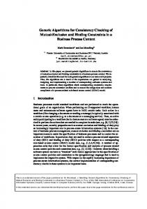
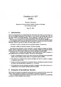
Figure 1: Four Variable Model.
2 Background: SCR Method
The purpose of a requirements document is to describe all acceptable system implementations [12]. To minimize implementation bias, a requirements document should specify only the externally visible behavior required of the system. To achieve this, Parnas has introduced the Four Variable Model, a standardarized model of embedded system behavior that describes the required system functions, timing, and precision [17]. This section reviews the constructs and tabular notation in SCR requirements speci cations in terms of the Four Variable Model. Because our initial requirements model emphasizes the system's functions, the discussion focuses on aspects of the Four Variable Model that describe functional behavior. SCR Constructs. The Four Variable Model, illustrated in Figure 1, represents requirements as a set of mathematical relations on four sets of variables called monitored, controlled, input, and output. A monitored variable represents an environmental quantity that in uences system behavior, a controlled variable an environmental quantity the system controls. A black box speci cation of required behavior is given as two relations (REQ and NAT) from the monitored quantities to the controlled quantities (not inputs to outputs). NAT de nes the set of possible values; it captures any constraints on behavior, such as those imposed by physical laws. REQ de nes the additional constraints imposed by the system to be built. It describes the required system behavior by de ning the relation the system must maintain between the monitored and the controlled quantities. Inputs and outputs are treated as resources. Inputs are resources available to the system to compute the monitored quantities. The relation IN de nes the mapping from the monitored quantities to the inputs. Similarly, the relation OUT de nes the mapping from the outputs to the controlled quantities. The use of monitored and controlled quantities to de ne required behavior, rather than inputs and outputs, keeps the speci cation in the problem domain and allows a simpler speci cation. Below, we refer to monitored variables and inputs as input variables, controlled variables and outputs as output variables. Four more constructs, all introduced in the A-7 requirements document [13], are useful for specifying systems using the Four Variable Model. These are modes, terms, conditions, and events. A mode class is a state machine, whose states are called system modes (or simply modes) and whose transitions are triggered by events. Complex systems are de ned by more than one mode class, operating in parallel. A term is any function of input variables, modes, or other terms. A 2
Pressure
High
Mode Class TooLow
{
Terms Permitted
{
Overridden . Constants . .
Low Permit . . .
Old Mode
TooLow
Safety Injection System WaterPres Block Env. Reset
Permitted
Safety Safety Injection Input Output Injection Output Sensor2 Software Device Env. Devices Devices Devices Sensor3 Sensor1
Permitted High
Event
@T(WaterPres @T(WaterPres @T(WaterPres @T(WaterPres
� Low) � Permit) < Low) < Permit)
New Mode
Permitted High TooLow Permitted
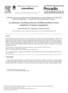
Table 1: Mode Transition Table for Pressure.
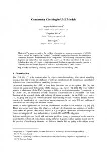
Figure 2: Requirements Spec. for Safety Injection. condition is a predicate about the system state. An event occurs when any system entity (that is, an input or output variable, mode, or term) changes value. A special event, called an input event, occurs when an input variable changes value. Another special event, called a conditioned event, occurs if an event occurs when a speci ed condition is true. To illustrate the SCR constructs, we consider a simpli ed version of the control system for safety injection described in [4]. The system uses three sensors to monitor water pressure and adds coolant to the reactor core when the pressure falls below some threshold. The system operator blocks safety injection by turning on a \Block" switch and resets the system after blockage by turning on a \Reset" switch. Figure 2 shows how SCR constructs could be used to specify the requirements of the control system. Water pressure and the \Block" and \Reset" switches are represented as monitored variables, WaterPres, Block, and Reset; safety injection as a controlled variable, Safety Injection; each sensor as an input; and the hardware interface between the control system software and the safety injection system as an output.1 A mode class Pressure and a term Overridden help make the speci cation concise. Pressure contains three modes, TooLow, Permitted, and High. A drop in water pressure below a constant Low causes the system to enter mode TooLow; an increase in pressure above a larger constant Permit causes the system to enter mode High. The term Overridden is true if safety injection is blocked, false otherwise. An example of a condition in the speci cation is \WaterPres < Low". Two examples of events are the input event @T(Block=On) (the operator turns Block from Off to On) and the conditioned event @T(Block=On) WHEN WaterPres < Low (the operator turns Block to On when water pressure is below Low). SCR Notation. The A-7 requirements document [13] introduced a special tabular notation for writing speci cations. Because tables are easy to understand, the tabular notation facilitates industrial application of the SCR method. Among the tables in SCR speci cations are condition tables, event tables, and mode transition tables. Each table de nes a function.2 A condition table describes an output variable or a term as a function of a mode and a condition, an event table describes either as a function of a mode and an event. A mode transition table describes a mode as a function of another mode and an event.
Mode
High
or
TooLow Permitted Overridden
Events
False @T(Block=On) WHEN Reset=Off True
@T(Inmode) @T(Inmode) OR @T(Reset=On) False
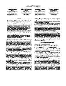
Table 2: Event Table for Overridden. While condition tables de ne total functions, event tables and mode transition tables may de ne partial functions, because some events cannot occur when certain conditions are true. For example, in the above system, the event, @T(Pressure=High) WHEN Pressure=TooLow, cannot occur, because starting from TooLow, the system can only enter Permitted when a state transition occurs. Tables 1{3 are part of REQ, the system requirements speci cation for the above control system. Table 1 is a mode transition table describing the mode class Pressure as a function of the current mode and the monitored variable WaterPres. Table 2 is an event table describing the term Overridden as a function of Pressure, Block, and Reset. Table 3 is a condition table describing the controlled variable Safety Injection as a function of Pressure and Overridden. Table 3 states, \If Pressure is High or Permitted or if Pressure is TooLow and Overridden is true, then Safety Injection is Off; if Pressure is TooLow and Overridden is false, then Safety Injection is On." The notation \@T(Inmode)" in a row of an event table describes system entry into the mode in that row; for example, \@T(Inmode)" in the rst row of Table 2 means, \If the system enters High, then Overridden becomes false."
3 Formal Requirements Model
Our requirements model, a state automaton model, de nes sets of modes, entity names, values, and types. It also introduces a function TY, which maps an entity to its legal values; in the sample system, TY(Overridden)=ftrue, falseg, TY(Sensor1)= [14; 2000], TY(Safety Injection)=fOn, Offg, and TY(Pressure)=fHigh, TooLow, Permittedg. The model de nes system state in terms of the entities, a condition as a predicate on the system state, and an input event as a change in an input variable that triggers a new system state. It then shows how a set of functions, called table functions, can be derived from the SCR tables. The table functions are used to de ne the system transform T, a special case of REQ which maps the current system state and an input event to a new system state. To provide a formal foundation for
The example omits the SCR brackets, e.g., *mode*, etc. Although SCR speci cations can be nondeterministic, our initial model is restricted to deterministic systems. 1 2
3
Mode
TooLow
Overridden
False NOT Overridden
Safety Injection
Off
On
High
or Permitted
event e = @T(c) can be expressed as the simple conditioned event e = @T(c) WHEN true. A conditioned event e is composed of simple conditioned events connected by the logical connectors ^ and _. We de ne the logical statement represented by a simple conditioned event as @T(c) WHEN d = NOT c ^ c0 ^ d, where the unprimed and primed versions of0 condition c denote c in0 di�erent states. We de ne c , where c = r v, as c = (r v)0 = r0 v. Based on these de nitions and the standard predicate calculus, any conditioned event can be expressed as a logical statement. Where a condition is evaluated in a single state, an event is evaluated in two states: unprimed conditions in the rst (or old) state, primed conditions in the second (or new) state. Ordering the Entities. To compute the value of an entity in the new state, the transform function may use the values of entities in both the old state and the new state. To describe the entities needed in the new state, we associate with each entity r a subset of RF called the new state dependencies set. Given entities r and r^ in RF, we say that r depends directly on r^ if r^ is in r's new state dependencies set. The \depends directly on" relation imposes a partial ordering on the set RF. Thus, the entities in RF can be ordered as a sequence R, where for all i and j such that ri and rj belong to R, ri depends directly on rj implies that ri follows rj in R (that is, i > j). Table Functions. Each SCR table describes a table function, called Fi, for some entity ri. Table functions de ne the values of the output variables, terms, and mode classes in SCR requirements speci cations. Each entity de ned by a table is associated with exactly one mode class, Mj , 1 � j � N. To represent the relation between an entity and a mode class, we de ne a function �, where �(i) = j i� entity ri is associated with mode class Mj . Using this notation, M�(i) denotes the mode class associated with entity ri. Presented below for condition, event, and mode transition tables is a typical format, a representation of the information in each table as a relation �i , and a set of properties which guarantee that �i is a function. Given �i , we can derive the table function Fi . Condition Tables. Table 4 shows a typical format for a condition table with n+1 rows and p+1 columns. Each condition table describes an output variable or term ri as a relation �i between modes, conditions, and values, i.e., �i = f(mj ; cj;k ; vk ) 2 M�(i) � Ci � TY(ri )g; where Ci is a set of conditions de ned on entities in RF. �i has the following four properties:
Conditions
True
Table 3: Condition Table for Safety Injection. consistency checking, we present below excerpts from our requirements model [10]. System State. We assume the existence of the following sets. � MS is the union of N pairwise disjoint sets, called mode classes. Each member of a mode class is called a mode. � TS is a union of data types, where each type is a nonempty set of values. � VS is a set of entity values with VS = MS [ TS. � RF is a set of entity names r. RF is partitioned into four subsets: MR, the set of mode class names; IR, the set of input variable names; GR, the set of term names; and OR, the set of output variable names. For all r 2 RF, TY(r) � VS is the type of entity r.
A system state s is a function that maps each entity name r in RF to a value. More precisely, for all r 2 RF: s(r) = v, where v 2 TY(r). Thus, by assumption, in any state s, the system is in exactly one mode from each mode class, and each entity has a unique value. Conditions. Conditions are de ned on the values of entities in RF. A simple condition c is either true, false, or a logical statement c = r v, where r 2 RF is an entity name, 2 f=; 6=; >;