Sep 17, 2010 - AbstractâIn this paper, the problem of human motion tracking ..... topology, which we will call Topology 2, the agent is located. Jj = â¡. â¢. â¢. â¢. â¢. â¢. â£. â .... connecting the true position of the agent and the center of the area ...
¨ 2010 INTERNATIONAL CONFERENCE ON INDOOR POSITIONING AND INDOOR NAVIGATION (IPIN), 15-17 SEPTEMBER 2010, ZURICH, SWITZERLAND
Constrained Maximum Likelihood Positioning for UWB Based Human Motion Tracking Zemene W. Mekonnen, Eric Slottke, Heinrich Luecken, Christoph Steiner, and Armin Wittneben Communication Technology Laboratory, ETH Zurich, 8092 Zurich, Switzerland {mekonnen, slottke, lueckenh, steinech, wittneben}@nari.ee.ethz.ch
Abstract—In this paper, the problem of human motion tracking with ultra-wideband radio nodes is addressed. We provide a general maximum likelihood formulation of the positioning problem based on range measurements which can handle synchronous and asynchronous agents. Geometrical constraints on the node topology, which are imposed by the human body, are also taken into account. For a Gaussian ranging error model and the specific problem of arm motion tracking, we derive the maximum likelihood estimation rule and calculate an analytical expression for the unconstrained and constrained Cram´er-Rao Lower Bound. With these results, we study analytically and via computer simulations under what circumstances the geometrical constraints lead to performance gains. It is found that the largest benefits are obtained in case of asynchronous agents and for certain arm positions. Intuitive reasons for this phenomenon are given. Finally, we verify these findings and evaluate the position location performance experimentally with range estimates obtained from measured ultra-wideband channel impulse responses including the impact of the human body.
I. I NTRODUCTION Assessing the motion of the human body is of interest in various disciplines. In medicine, for instance, motion tracking systems make it possible to assist stroke patients in the process of rehabilitation by providing means to record and analyze their gait [1], [2]. In a similar fashion, professional athletes are able to use such a system to improve their training. The entertainment industry also employs motion capture systems to record the movement of actors. The recorded data can later be used to create realistically animated computer generated imagery. Corresponding to the wide area of applications, there exist several technical approaches to perform human motion tracking. The most prominent among these are based on optical, inertial and magnetic sensing or time-of-flight based technologies (or a combination of them). Optical systems (e.g. [3], [4]), while providing reliable tracking, require dedicated infrastructure, complex settings and highly skilled operators. Inertial and magnetic systems (e.g. [5]), on the other hand, do not have line of sight (LOS) restriction but they are prone to drift errors and interferences from nearby ferromagnetic materials. Time-of-flight systems can be based on ultra-sonic [6] or radio wave propagation. For the latter case, one approach is motion tracking by means of ultra-wideband (UWB) radio communication, which is one of the most promising technologies for future body area networks [7], [8]. The very large bandwidth from 3.1 to 10.6 GHz enables localization c IEEE 978-1-4244-5864-6/10$26.00 ⃝
with high accuracy [9], [10]. Moreover, UWB meets the key requirements of mobile human motion tracking: low cost, small form factor and low energy consumption. By exploiting the large signal bandwidth, body mounted UWB nodes can determine their relative distances with very high spatiotemporal resolution and perform motion tracking based on this metric. Combined with the fact that such a system needs no external infrastructure, UWB positioning systems are particularly interesting for human motion tracking and can even be implemented as secondary application of an existing communication centric UWB body area network. In this paper, we investigate UWB-based human motion tracking and analyze its accuracy both theoretically and with measurements. Due to the harsh propagation environment in vicinity of the human body, the positioning accuracy can be degraded [11]. The major sources of this impairment are multipath propagation, potential non-line of sight conditions and the limited choice of fixed anchor node positions on the human body. To overcome these problems, we investigate the improvement in the positioning accuracy by taking the a priori knowledge about the body geometry into account. For example, an elbow joint only has limited degrees of freedom with respect to its corresponding shoulder; or loosely speaking: the hand can not reach positions that are 3 meters away from the torso. This information can be interpreted as additional reference measurements, which improves the positioning. Our goal is to understand and quantify benefits of constrained positioning in this context. The results are verified by simulation and measurements. The remainder of this paper is organized as follows. In Section II, we define the investigated positioning system and formally phrase the motion tracking with a priori knowledge as an optimization problem. Section III then presents the constrained maximum likelihood estimation for the general case as well as under consideration of the specific geometric constraints of tracking the movement of an arm. Afterwards, the theoretical limits of the estimation performance are analyzed in Section IV by deriving the Cram´er-Rao lower bounds for both a geometrically constrained and unconstrained estimator. These limits are compared to the estimator performance found by computer simulations in Section V for fixed and random node topologies. The results obtained by computer simulation are further supported in Section VI, where a measurement setup and measured position estimation performances are presented. Finally, conclusions are drawn in Section VII.
II. S YSTEM S ETUP AND P ROBLEM F ORMULATION In the following, we investigate an UWB based motion tracking system, which is made up of two types of communicating nodes. The first type are reference nodes with known positions, commonly called anchors. The anchor nodes share a common reference timing, i.e. they are synchronized. The movement of the body is tracked by determining the position of a second type of nodes called agents with unknown positions. In order to localize the agents, each agent node transmits a signal to the receiving anchors. By observing the time of arrival (TOA) metric of the signals, which corresponds to the electromagnetic propagation delay, each anchor can determine its distance to the transmitting agent’s position. These distance measurements can be used together with the known anchor positions to localize the corresponding agent relative to the anchors. The set of agent nodes may share the synchronized timing of the anchors, however, they may be unsynchronized in general. In the latter case, the TOA cannot be directly measured, as the time of departure is not known to the receiving anchors. This corresponds to the received signals of each agent having a timing offset, which is unknown to the anchors or equivalently an offset in the distance measurements belonging to the corresponding agent. A common way to handle the case of asynchronous agents is to define one anchor as reference and determine the time difference of arrival (TDOA) with respect to this reference instead [12]. The measured time differences can then be used to localize the agents. However, as we will show in the following, it can be feasible to perform positioning based on TOA information rather than TDOA even if the agents are asynchronous. The system setup we consider is shown in Fig. 1(a). This system employs anchor nodes mounted directly on the body. It would also be possible to install anchors at fixed positions in the vicinity to the body, however, this would limit the flexibility of the system since additional infrastructure is needed. We thus require the position of the body mounted anchors to be known a priori. To achieve this, the anchors are mounted on a fixed part of the body, e.g. the torso. The agent nodes are considered to be transmit-only nodes, since agents should preferably be of low complexity due to cost and size constraints. We allow the agents to be synchronous or asynchronous to the anchors. The distance between each agent and all anchors is determined from TOA information, inducing an unknown distance offset for each agent in the asynchronous case. With this system setup, tracking the movement of the limbs corresponds to the localization problem shown in Fig𝑁𝑟 represent the 𝑁𝑟 anchor nodes, ure 1(b). Herein {𝑅𝑖 }𝑖=1 𝑁𝑎 𝑁𝑠 represent joints {𝐴𝑖 }𝑖=1 denote the 𝑁𝑎 agents, and {𝑆𝑖 }𝑖=1 whose positions are known a priori (e.g. the shoulder and the hip joints). Let the physical parameters of the body (which are also known a priori) be denoted by the vec(𝑥) (𝑦) (𝑧) (𝑥) (𝑦) (𝑧) tor 𝝎 = [𝑆1 , 𝑆1 , 𝑆1 , . . . , 𝑆𝑁𝑠 , 𝑆𝑁𝑠 , 𝑆𝑁𝑠 , 𝑙1 , . . . , 𝑙𝑁𝑙 ]𝑇 , (𝑥) (𝑦) (𝑧) 𝑇 where 𝑆𝑖 = [𝑆𝑖 , 𝑆𝑖 , 𝑆𝑖 ] represents the position of
(a) Fig. 1.
(b)
(a) System setup. (b) Limb movement tracking. 𝑁
𝑙 joint 𝑆𝑖 and {𝑙𝑁𝑙 }𝑖=1 are the physical lengths of the limbs. Similarly, define a vector of the unknown parameters as (𝑥) (𝑦) (𝑧) (𝑥) (𝑦) (𝑧) 𝜽 = [𝐴1 , 𝐴1 , 𝐴1 , 𝑏1 , . . . , 𝐴𝑁𝑎 , 𝐴𝑁𝑎 , 𝐴𝑁𝑎 , 𝑏𝑁𝑎 ]𝑇 , where 𝑏𝑗 is the range measurement offset of agent 𝑗. It is unknown in the asynchronous case. The 𝑁𝑟 𝑁𝑎 range measurements are denoted by 𝒅ˆ = [𝑑ˆ11 , 𝑑ˆ12 , . . . 𝑑ˆ1𝑁𝑎 , 𝑑ˆ21 , . . . , 𝑑ˆ𝑁𝑟 𝑁𝑎 ]𝑇 , where 𝑑ˆ𝑖𝑗 is the result of a range measurement between the 𝑖th anchor and 𝑗th agent. With this formulation, the problem that we want to solve ˆ estimate 𝜽 is the following: given the range measurements 𝒅, under the constraints ⎤ ⎡ 𝑐1 (𝜽, 𝝎) ⎢ 𝑐2 (𝜽, 𝝎) ⎥ ⎥ ⎢ (1) 𝒄 (𝜽, 𝝎) = ⎢ ⎥ = 0, .. ⎦ ⎣ . 𝑐𝑁𝑐 (𝜽, 𝝎)
𝑁
𝑐 where {𝑐𝑖 (𝜽, 𝝎) = 0}𝑖=1 are functions that represent the topology constraints of the agents, which are defined by their placement on the body.
III. C ONSTRAINED M AXIMUM L IKELIHOOD S OLUTION In this section, we develop the maximum likelihood (ML) solution for the constrained localization problem introduced in Section II. Assuming statistically independent ranging errors, the likelihood function for 𝜽 can be expressed as 𝑁𝑎 ∏ 𝑁𝑟 ( ) ∏ ) ( (2) 𝑝 𝑑ˆ𝑖𝑗 𝜽 = 𝜽 ′ , 𝑝 𝒅ˆ 𝜽 = 𝜽 ′ = 𝑗=1 𝑖=1 ′
where 𝜽 denotes the trial value for 𝜽. Hence, the ML estimator which jointly estimates the position of all the agents and their respective range measurement offset, subject to the constraints in (1), is given by 𝑁𝑎 ∏ 𝑁𝑟 ( ) ∏ ˆ𝑖𝑗 𝜽 = 𝜽 ′ , 𝑝 𝑑 s.t. 𝒄 (𝜽 ′ , 𝝎) = 0. 𝜽ˆ = arg max ′ 𝜽
𝑗=1 𝑖=1
The measured distance between the 𝑖th anchor and 𝑗th agent can be expressed as (3) 𝑑ˆ𝑖𝑗 = 𝑑𝑖𝑗 + 𝑏𝑗 + 𝑒𝑖𝑗 ,
−−−→ where 𝑑𝑖𝑗 ≜ 𝑅𝑖 𝐴𝑗 is the true distance between the 𝑖th anchor and 𝑗th agent, 𝑏𝑗 is the range measurement offset, and 𝑒𝑖𝑗 is the error of the range measurement between the 𝑖th anchor and 𝑗th agent. If the ranging errors are modeled as zero mean independent Gaussian random variables, i.e. ) ( −−−→ 2 , 𝑑ˆ𝑖𝑗 ∼ 𝒩 𝑅𝑖 𝐴𝑗 + 𝑏𝑗 , 𝜎𝑖𝑗
anchor with the smallest variance is given the largest weight. If alternatively a TDOA approach would be used, the impact of the range measurement offsets on the position estimate is taken out by subtracting the range measurement of a reference anchor from the range measurements of all the other anchors. If we choose, without loss of generality, anchor 𝑅1 as the reference anchor the position estimate is performed using a range difference vector given by [ ]𝑇 ˆ2𝑗 − 𝑑ˆ1𝑗 , . . . , 𝑑ˆ𝑁 𝑗 − 𝑑ˆ1𝑗 = 𝑑 𝒅TDOA 𝑗 𝑟
then the likelihood function of 𝜽 takes the form ( ( �−−−→� )2 ) 𝑁𝑎 ∏ 𝑁𝑟 � � ( ) ∏ 𝑑ˆ𝑖𝑗 −�𝑅𝑖 𝐴′𝑗 �−𝑏′𝑗 ′ 1 √ 2 exp − 𝑝 𝒅ˆ 𝜽 = 𝜽 = . for 𝑗 = {1, . . . , 𝑁 }. 2 2𝜎𝑖𝑗 𝑎 2𝜋𝜎𝑖𝑗 𝑗=1 𝑖=1 In contrast to the sufficient statistics that we derived in (8), Accordingly, the ML estimate of 𝜽 results to the computationally simple TDOA approach is sensitive to −−−→ ( )2 the choice of the reference node. If the error variance of the 𝑁𝑎 ∑ 𝑁𝑟 𝑑ˆ − 𝑅𝑖 𝐴′𝑗 − 𝑏′𝑗 ∑ 𝑖𝑗 reference anchor node is large, it will propagate through all the , 𝜽ˆ = arg min range differences, resulting in a poor positioning performance. 2 𝜽′ 𝜎𝑖𝑗 𝑗=1 𝑖=1 The ML approach, however, is robust to this problem as the s.t. 𝒄 (𝜽 ′ , 𝝎) = 0. (4) range measurements with large error variance are given a small In the synchronous case, the range measurement offsets are weight. Applying the sufficient statistics in (8) results in the ML known (and in fact are zero), however, when the agents are estimate of 𝜽, which can be expressed by1 asynchronous the offsets have to be estimated jointly with the position variables. For this, we will derive a sufficient statistics for the ML estimate of 𝜽, which implicitly includes the ML estimate of the range measurement offsets. 𝑁𝑎 , the cost For a given set of trial agent positions {𝐴′𝑖 }𝑖=1 function in (4) takes on an expression of the form )2 𝑁𝑎 ∑ 𝑁𝑟 ( ∑ 𝜓𝑖𝑗 − 𝑏′𝑗 ′ ′ , Ψ(𝑏1 , . . . , 𝑏𝑁𝑎 ) = 2 𝜎𝑖𝑗 𝑗=1 𝑖=1 −−−→ where 𝜓𝑖𝑗 = 𝑑ˆ𝑖𝑗 − 𝑅𝑖 𝐴′𝑗 . Hence, the offset of agent 𝑗 that minimizes the cost function in (4) satisfies ∂Ψ(𝑏′1 , . . . , 𝑏′𝑗 , . . . , 𝑏′𝑁𝑎 ) = 0. ∂𝑏′𝑗
(5)
For asynchronous agents the range measurement offsets are independent and (5) results in ) 𝑁𝑟 ( ∑ 𝜓𝑖𝑗 − 𝑏′𝑗 = 0. (6) 2 𝜎𝑖𝑗 𝑖=1 Thus, we obtain
−−−→ 𝑁𝑟 𝑅𝑖 𝐴′𝑗 ∑ 1 ¯ 1 ′ 𝑏𝑗 = 𝑑 𝑗 − , 2 𝛾¯𝑗 𝛾¯𝑗 𝑖=1 𝜎𝑖𝑗
where we have defined 𝛾¯𝑗 =
𝑁𝑟 ∑ 𝑖=1
1 2 𝜎𝑖𝑗
(7)
𝑁𝑟 ∑ and 𝑑¯𝑗 =
𝑖=1
[ ]𝑇 1 1 𝒅˜𝑗 = 𝑑ˆ1𝑗 − 𝑑¯𝑗 , . . . , 𝑑ˆ𝑁𝑟 𝑗 − 𝑑¯𝑗 𝛾¯𝑗 𝛾¯𝑗
𝑑ˆ𝑖𝑗 2 . 𝜎𝑖𝑗
Hence, (8)
for 𝑗 = {1, . . . , 𝑁𝑎 }, is a sufficient statistics for the ML estimate of the agents position. We notice that 𝛾¯1𝑗 𝑑¯𝑗 is a weighted average of the distance measurements for agent 𝑗, where the measurement from the
𝜽ˆ = arg min ′ 𝜽
𝑁𝑎 ∑ 𝑗=1
′ ˜ (𝒅˜𝑗 − x𝑗 (𝜽 ′ ))𝑇 Σ−1 𝑗 (𝒅𝑗 − x𝑗 (𝜽 )),
s.t. 𝒄 (𝜽 ′ , 𝝎) = 0,
(9)
where the 𝑖th element of the� vector x𝑗 (𝜽 ′ ) is given by � −−−→ �−−−→ ′� 𝑁 𝑟 ∑ �𝑅 𝑘 𝐴𝑗 � [x𝑗 (𝜽 ′ )]𝑖 = 𝑅𝑖 𝐴′𝑗 − 𝛾¯1𝑗 and Σ𝑗 is a diagonal 𝜎2 𝑘=1
2 . matrix with entries [Σ𝑗 ]𝑖𝑖 = 𝜎𝑖𝑗
𝑘𝑗
Example: Arm Motion Tracking As an example, we consider the problem of tracking an arm. The node configuration is shown in Figure 1(b). For the sake of visualization, we will only discuss the case of 2D motion tracking. We note that for this specific case, 𝜽 = (𝑥) (𝑦) (𝑥) (𝑦) (𝑥) (𝑦) [𝐴1 , 𝐴1 , 𝑏1 , 𝐴2 , 𝐴2 , 𝑏2 ]𝑇 and 𝝎 = [𝑆1 , 𝑆1 , 𝑙1 , 𝑙2 ]𝑇 . Moreover, the topology constraints, which take the lengths of the forearm and upper arm into account, can be expressed as ⎤ ⎡ ( )2 ( )2 (𝑥) (𝑥) (𝑦) (𝑦) 2 + 𝐴1 − 𝑆1 − 𝑙1 ⎥ ⎢ 𝐴1 − 𝑆1 )2 ( )2 𝒄 (𝜽, 𝝎) = ⎣ ( ⎦. (𝑥) (𝑥) (𝑦) (𝑦) + 𝐴2 − 𝐴1 − 𝑙22 𝐴2 − 𝐴1 (10) Depending on the employed system setup (synchronous or asynchronous), the ML estimate of agent 𝐴1 and 𝐴2 can then be found from (4) or (9) by applying constrained optimization techniques. However, for this specific node topology, the constraints can easily be integrated into the cost function to result in an ML estimator with a reduced number of variables as discussed below. To keep the exposition short, we will only consider the asynchronous case. The synchronous case follows immediately. 1 Note
that the offsets, which are implicitly estimated, are given by (7).
With (10), the y-coordinates of each trial position can be expressed as a function of the respective x-coordinates √ ( ) (𝑦)
𝐴1 = 𝜅1 (𝑦)
𝐴2 = 𝜅2
(𝑥)
√
(𝑥)
𝑙12 − 𝐴1 − 𝑆1
2
( )2 (𝑥) (𝑥) 𝑙22 − 𝐴2 − 𝐴1 √ ( + 𝜅1
(𝑦)
+ 𝑆1
(𝑥)
and (11)
(𝑥)
𝑙12 − 𝐴1 − 𝑆1
)2
(𝑦)
𝜽ˆ satisfies [13] ( ) ( )−1 𝐸 (𝜽ˆ − 𝜽)𝑇 (𝜽ˆ − 𝜽) ≥ 𝑱 −1 −𝑱 −1 𝑪 𝑇 𝑪𝑱 −1 𝑪 𝑇 𝑪𝑱 −1 . (15) To illustrate these results, we shall next discuss the CRLB for the arm motion tracking example that has been presented in the previous section. Example: CRLB for Arm Motion Tracking
+ 𝑆1 ,
where 𝜅1 , 𝜅2 ∈ {+1, −1} represent the four possible sign combinations of the y-coordinates that satisfy the length constraint for given x-coordinates. Moreover, we note that (11) comes along with the (𝑥) (𝑥) (𝑥) boundary conditions 𝐴1 ∈ [𝑆1 − 𝑙1 , 𝑆1 + 𝑙1 ] and (𝑥) (𝑥) (𝑥) 𝐴2 ∈ [𝑆1 − 𝑙1 − 𝑙2 , 𝑆1 + 𝑙1 + 𝑙2 ]. Hence, for a given sign combination 𝜅1 and 𝜅2 an estimator for 𝜽, which takes into account the topology constraints is equivalent to an (𝑥) (𝑥) estimator for 𝜷 = [𝐴1 , 𝐴2 ]𝑇 with the respective boundary conditions. The ML estimate of {𝜷, 𝜅1 , 𝜅2 } can then be found by inserting (11) into (9).
The constraint functions for the 2D arm motion tracking problem are given in (10). Calculating the gradient matrix for these constraints results in 𝑪(𝜽, 𝝎) = [ (𝑥) (𝑥) 𝐴1 −𝑆1 2 (𝑥) (𝑥) 𝐴1 −𝐴2
𝒄 (𝜽, 𝝎) = 0.
(12)
Define the 𝑁𝑐 × 4𝑁𝑎 gradient matrix of the constraints as2 ∂𝒄(𝜽, 𝝎) . ∂𝜽 𝑇
(13)
The gradient matrix 𝑪(𝜽, 𝝎) is assumed to have full rank for any 𝜽 satisfying the constraints (i.e. the constraints are not redundant). The Fisher information matrix (FIM) for the unconstrained parameter estimation problem is given by [13] ) ( (14) 𝑱 = 𝐸 ΔΔ𝑇 , ∂ ln(𝑝( 𝒅ˆ∣𝜽)) where Δ = . Given this formulation, if 𝑱 is pos∂𝜽 itive definite, the covariance matrix3 of the unbiased estimate 2 4𝑁
⎡ ⎢ ⎢ ⎢ 𝑱𝑗 = ⎢ ⎢ ⎣
notational simplicity.
2
(𝐴𝑗(𝑥) −𝑅𝑖(𝑥) ) −−→ 2 2 𝑅𝑖 𝐴𝑗 ∥ 𝑖=1 𝜎𝑖1 ∥− (𝑥) (𝑦) (𝑥) (𝑦) 𝑁 𝑟 𝐴 𝐴 −𝑅 −𝑅 ∑ ( 𝑗 𝑖 )( 𝑗 𝑖 ) −−−→ 2 2 𝜎 𝑅 𝐴 𝑖=1 𝑖𝑗 ∥ 𝑖 𝑗 ∥ (𝑥) (𝑥) 𝑁 𝑟 (𝐴 −𝑅 ∑ 𝑗 𝑖 ) −−−→ 2 𝑖=1 𝜎𝑖𝑗 ∥𝑅𝑖 𝐴𝑗 ∥ 𝑁 𝑟 ∑
0
(𝑦)
(𝑦)
0
𝐴1 −𝐴2
0 (𝑥)
(𝑦)
0 (𝑦)
𝐴2 −𝐴1
]
0
.
For the Gaussian ranging error model, the log-likelihood function of 𝜽 takes the form ) ( ( ) ℒ 𝒅ˆ 𝜽 = ln 𝑝( 𝒅ˆ 𝜽) 𝑁𝑟 ∑ 2 ∑
ln 𝜎𝑖𝑗
𝑖=1 𝑗=1
−
−−−→ ( )2 ˆ𝑖𝑗 − 𝑁𝑟 ∑ 2 − 𝑏 𝑅 𝐴 𝑑 ∑ 𝑖 𝑗 𝑗 1 2
𝑖=1 𝑗=1
2 𝜎𝑖𝑗
.
Using this log-likelihood function and applying (14) results in the FIM for the unconstrained estimation of 𝜽 of the form [ ] 𝑱1 0 𝑱= , (17) 0 𝑱2 with the expression for 𝑱𝑗 given by (18). The CRLB for the covariance matrix of the estimate of 𝜽 can then be calculated by inserting (16) and (17) into (15). V. S IMULATION -BASED P ERFORMANCE A NALYSIS In this section, we discuss numerical results which assess the performance of the ML estimator presented in Section III. To understand the impact of the topology of the nodes on the estimator performance, we will first consider the two specific agent node topologies that are shown in Figure 2. For the first topology, which we will call Topology 1 in the following, agent 𝐴2 is located at wrist position 𝑊1 : (30 cm, 30 cm), with the shoulder joint 𝑆1 being chosen as the center of the Cartesian coordinates. Whereas for the second topology, which we will call Topology 2, the agent is located
(𝐴𝑗(𝑥) −𝑅𝑖(𝑥) )(𝐴𝑗(𝑦) −𝑅𝑖(𝑦) ) −−−→ 2 𝜎 2 ∥𝑅𝑖 𝐴𝑗 ∥ 𝑖=1 𝑖𝑗 (𝑦) (𝑦) 2 𝑁 𝑟 𝐴 ∑ ( 𝑗 −𝑅𝑖 ) −−−→ 2 2 𝑖=1 𝜎𝑖𝑗 ∥𝑅 𝑖 𝐴𝑗 ∥ (𝑦) (𝑦) 𝑁 𝑟 (𝐴 −𝑅 ∑ 𝑗 𝑖 ) −−−→ 2 𝑖=1 𝜎𝑖𝑗 ∥𝑅𝑖 𝐴𝑗 ∥ 𝑁 𝑟 ∑
(𝑥)
0
𝐴2 −𝐴1
= − 𝑁𝑟 ln (2𝜋) −
In this section we discuss the Cram´er-Rao lower bound (CRLB) for the estimate of 𝜽 under the constraints given in (1). For this we use the results presented in [13], which may be summarized as follows. Let 𝜽ˆ be an unbiased estimate of 𝜽 that satisfies the continuously differentiable constraints
𝑎 is the number of elements of 𝜽. 3 The argument of 𝑪(𝜽) is omitted for
(𝑦)
(16)
IV. C RAM E´ R -R AO L OWER B OUND
𝑪(𝜽, 𝝎) =
(𝑦)
𝐴1 −𝑆1
(𝐴𝑗(𝑥) −𝑅𝑖(𝑥) ) −−−→ 2 𝑖=1 𝜎𝑖𝑗 ∥𝑅𝑖 𝐴𝑗 ∥ (𝑦) (𝑦) 𝑁 𝑟 𝐴 ∑ ( 𝑗 −𝑅𝑖 ) −−−→ 2 𝜎 𝑅 𝐴 𝑖=1 𝑖𝑗 ∥ 𝑖 𝑗 ∥ 𝑁 𝑟 ∑
𝑁 𝑟 ∑ 𝑖=1
1 𝜎2 𝑖𝑗
⎤ ⎥ ⎥ ⎥ ⎥ for 𝑗 = {1, 2} ⎥ ⎦
(18)
−50
y [cm]
0
50 Constrained Unconstrained Topology 1 Topology 2
(a) Topology 1 100 −50
0
50
100
x [cm]
(a) Synchronous −50
0 y [cm]
(b) Topology 2 Fig. 2. Node topologies for arm motion tracking. (a) is defined as Topology 1, (b) is defined as Topology 2.
50
at wrist position 𝑊2 : (60 cm, 0 cm). For both topologies, agent 𝐴1 is located at elbow position 𝐸 : (30 cm, 0 cm) and the anchors are placed on the torso at 𝑅1 : (−20 cm, 0 cm), 𝑅2 : (−35 cm, 20 cm), 𝑅3 : (−5 cm, 20 cm) and 𝑅4 : (−20 cm, 40 cm). For the simulations the ranging error is independent and identically distributed with a standard deviation of 0.316 cm. Figure 3(a) shows the position estimates for the synchronous case (anchors and agents are perfectly synchronous in time). In the figure, crosses represent the position estimates for topology 1 and circles denote the position estimates for topology 2. The estimates from the constrained estimator are represented in green and the unconstrained estimates are marked by blue. The empirical root mean squared error (RMSE) of the position estimates is given in columns 3 and 5 of Table I. For both topologies the RMSE of the elbow estimates is improved by a factor of 3 when imposing the topology constraints. For topology 1, the wrist sees no improvement by invoking the constraints. For topology 2, however, the wrist RMSE improves by a factor of 2. The position estimates for the asynchronous case are shown
Constrained Unconstrained Topology 1 Topology 2
100 −50
0
50
100
x [cm]
(b) Asynchronous Fig. 3. Performance of the ML position estimator for two characteristic agent topologies in synchronous and asynchronous mode.
in Figure 3(b) and the corresponding RMSE of the position estimates are given in columns 2 and 4 of Table I. The first thing that we notice from the results is that the position estimates for the unconstrained case form an ellipsoidal cloud, which we will call error cloud. The center of the cloud is located around the true position of the agent and its main axis is approximately oriented in the direction of the line connecting the true position of the agent and the center of the area spanned by the anchors. In order to get an intuition on this behavior we like to think of the range measurement offset as an error which moves the agent away from or towards the anchor from which
TABLE I S IMULATED RMSE OF AGENT POSITION ESTIMATES FOR THE SYNCHRONOUS AND ASYNCHRONOUS CASES . Unconstrained Estimation. Elbow Wrist Constrained Estimation Elbow Wrist
Topology 1 (async.)
Topology 1 (sync.)
Topology 2 (async.)
Topology 2 (sync.)
6.86 cm 5.06 cm
0.67 cm 0.63 cm
6.79 cm 13.37 cm
0.64 cm 0.96 cm
Topology 1 (async.)
Topology 1 (sync.)
Topology 2 (async.)
Topology 2 (sync.)
0.44 cm 4.10 cm
0.20 cm 0.63 cm
0.22 cm 0.65 cm
0.17 cm 0.41 cm
Cumulative Distribution Function
1
0.8
0.6
Constrained Unconstrained
0.4 Elbow MLE Wrist MLE
0.2
Elbow CRLB Wrist CRLB
0 0
Fig. 4.
0.5 1 Root Mean Square Error [cm]
Impact of ranging measurement offset on the position estimates.
1.5
(a) Synchronous
A comparison of the unconstrained results in Table I shows that the asynchronous mode effects a dramatic increase of the RMSE (about a factor of 10). This is also evident from the blue error clouds in Figure 3(a) and 3(b). Keeping in mind that the standard deviation of the ranging error is only 0.31 cm, the asynchronous, unconstrained scenario clearly has unacceptable performance (note for example the 13.37 cm RMSE of the wrist for topology 2). One might conclude from this figure that the asynchronous operation is hardly an option for our motion tracking application. The situation completely changes when we look at the constrained estimator. The asynchronous operation in most cases increases the RMSE by just a factor of 2. From the error clouds in Figure 3(b), we note that only the wrist position estimate in topology 1 degrades more severely from 0.63 cm (synchronous, constrained) to 4.1 cm (asynchronous, constrained). This is due to the fact that in topology 1 the wrist can move along the orientation axis of its error cloud, so the topology constraint does not provide additional information about the location of the agent here. For topology 2, however, the possible wrist movement is constrained to a circle which cuts the error cloud perpendicular to its orientation axis. Accordingly, the topology constraint provides a good performance gain for this case. We further notice that the RMSE of the elbow position estimate increases from 0.22 cm in topology 2 (constrained, asynchronous) to 0.44 cm in topology 1 (constrained, asynchronous). This is due to the fact that the elbow and the wrist positions are estimated jointly, and hence the uncertainty in the wrist position (which is worse in topology 1 as compared to that of topology 2) affects the elbow position estimate. From these observations, we may therefore conjecture that
1 Cumulative Distribution Function
the range measurement is taken. This effect is graphically explained in Figure 4 for two anchors. As shown in the figure, the measurement offset introduces a position estimation error along the line connecting the anchor and the agent. The joint effect of the error contributions from all the anchors results in a position estimation error whose axis is oriented in the direction of the line connecting the true position of the agent and the midsection of the line between the two anchor nodes.
0.8
0.6
Constrained Unconstrained
0.4 Elbow MLE Wrist MLE
0.2
Elbow CRLB Wrist CRLB
0 0
2
4 6 8 Root Mean Square Error [cm]
10
(b) Asynchronous Fig. 5.
CDF plot of the RMSE of the ML estimator and the CRLB.
the largest gain from considering topology constraints is achieved when the arm is along the line between the shoulder and the center of the area formed by the anchors. In summary, we conclude that the constrained ML estimation is a key to low cost asynchronous UWB motion tracking. By now it is evident that the agent topology has a strong impact on the estimator performance. In order to quantify this effect, we have evaluated the RMSE for a large number of random agent topologies that satisfy the constraint in (10). Due to the random topologies the RMSE values are random variables. Figure 5(a) and 5(b) show cumulative density function (CDF) for the synchronous and asynchronous case, respectively. Again all ranging errors have a standard deviation of 0.316 cm. For reference, we also show the corresponding CRLB (solid lines). In the synchronous case both the constrained and the unconstrained estimators closely approach the CRLB. Note that in the CDF plots the CRLB should be above the simulated performance. The minor deviations from this rule in Figure 5 are attributed to the finite sample size. The median (50 %) RMSE in the unconstrained, synchronous case is about 0.55 cm for both elbow and wrist. The constrained estimator improves these values to 0.25 cm (elbow) and 0.35 cm (wrist).
Anchor 1
3
Agent 1
3 Envelope Signal η1
PN seq. library
2 70%
cross correlation
IRs
. . .
. . .
record signal
h(t)
PN seq. 1
Anchor N Agent M
PN seq. M
PN seq. library
record signal
cross correlation
IRs
2
1
1
0
0
−1
−1
−2
−2
−3 0
10
20
30
40
50
−3
t in [ns]
Fig. 6.
Generalized block diagram of the measurement system
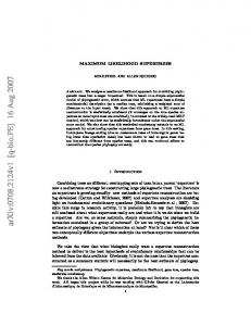
In the asynchronous case (Figure 5(b)) the unconstrained estimator produces an RMSE above 10 cm in 25 % (elbow) / 35 % (wrist) of all random topologies. Note the substantial impact of the constrained estimation. The median RMSE is 0.5 cm (elbow) / 1 cm (wrist) as compared to 4.4 cm / 5.5 cm in the unconstrained case. From the RMSE CDF plots of both the synchronous and asynchronous case, we further notice that for the constrained case the elbow position estimates are better than those of the wrist. This is expected as the movement of the agent at the elbow has less degrees of freedom compared to that of the agent at the wrist. From these results, we conclude that taking into account the topology constraints improves localization accuracy. The performance gain that can be obtained by the constraints is more pronounced when the agents are asynchronous. VI. P ERFORMANCE E VALUATION BY M EASUREMENTS In the previous section, the positioning improvement by use of geometric constraints has been numerically investigated. In order to validate the simulation results, we have conducted a measurement campaign, which is presented in the following. We use a measurement system with low-complexity asynchronous agent nodes as transmitters and synchronous anchors as receivers. This corresponds to the asynchronous case of the system definition in Section II. A block diagram of the implemented system is shown in Figure 6. In general, every agent broadcasts a unique and periodically repeated PN sequence 𝑥𝑗 (𝜏 ), where 𝑗 denotes the agent node index. The transmitted sequences are known to the anchors, however, each sequence will be shifted with respect to the anchor reference timing by an unknown offset due to lack of synchronization. The signal 𝑦𝑖 (𝜏 ) received at the 𝑖th anchor node is stored and subsequently correlated with each of the known PN sequences, thus generating a set of impulse responses which contain the TOA information: ℎ𝑖𝑗 (𝑡 − 𝑡𝑗 − 𝑡𝑖𝑗 ) = ℱ −1 {ℱ{𝑥𝑗 (𝜏 )}∗ ⋅ ℱ{𝑦𝑖 (𝜏 )}}. Herein, ℱ{⋅} denotes the Fourier transform. The impulse responses ℎ𝑖𝑗 are shifted in time by the unknown agent offset
η
2
12 13 t in [ns]
Fig. 7. TOA estimation scheme with sample impulse response. The initial search window is shown on the left, the second search interval on the right.
𝑡𝑗 and the propagation delay 𝑡𝑖𝑗 , which corresponds to the distance of interest. Due to additive noise and multipath propagation it is not always straightforward to estimate the TOA, i.e. the joint delay 𝑡𝑗 + 𝑡𝑖𝑗 . There exist several approaches in literature for estimating the TOA from the impulse responses (see [14], [11] and [15]). The estimator we employ is based on the jump back and search forward technique described in [16]. On the basis of a typically observed impulse response, Fig. 7 exemplifies the estimation procedure. It consists of two steps: in the first step, shown on the left, a search interval of length Δ1 = 20 ns is defined in front of the global maximum of the envelope signal, which is given by 𝑡max = arg max ∣ℎa (𝑡)∣ , 𝑡
ℎa (𝑡) = ℎ(𝑡) + 𝑗ℋ{ℎ(𝑡)}, with ℎa (𝑡) being the analytic version of the impulse response and ℋ{⋅} denoting the Hilbert transform. The algorithm then searches this window for the first occurrence of the envelope exceeding a predefined reference level 𝜂1 , which is chosen to 30 % of the global maximum: 𝑡1 = min 𝑡 𝑡
s.t. ℎa (𝑡) > 𝜂1 , 0 ≤ 𝑡max − 𝑡 ≤ Δ1 . After the point 𝑡1 has been found, a starting position for a refined search, shown on the right in Fig. 7, is generated by searching for the local maximum of the envelope in a search window of size Δ2 = 1 ns after 𝑡1 : 𝑡2 = arg max ∣ℎ𝑎 (𝑡)∣ 𝑡
s.t. 𝑡1 ≤ 𝑡 ≤ 𝑡1 + Δ2 . In a final step, the time of arrival estimation 𝑡TOA is found by searching for the first occurrence of the envelope exceeding the threshold 𝜂2 , which is defined to be 30 % of the local maximum ∣ℎa (𝑡2 )∣. This search is limited to a search window in front of 𝑡2 that, again, has a size of Δ2 = 1 ns: 𝑡TOA = min 𝑡 𝑡
s.t. ℎa (𝑡) > 𝜂2 , 0 ≤ 𝑡2 − 𝑡 ≤ Δ2 .
TABLE II E STIMATED M EASUREMENT S IGNAL - TO -N OISE -R ATIO (R ATIO OF PULSE ENERGY AND NOISE POWER SPECTRAL DENSITY ) Body
51.45 dB 49.80 dB 48.39 dB
51.48 dB 49.63 dB 48.14 dB
The measurements were conducted in the standard laboratory environment depicted in Figure 8. We study the arm tracking problem based on the two characteristic topologies used in the simulation Section (Fig. 2). Thus, the measurement setup employs two agent nodes and four anchors. Figure 8(a) shows the transmitter hardware of the agents consisting of the two PN sequence generators on the left and the power amplifiers on the right. The transmitted sequences have a length of 215 − 1 bits and a data rate of 10 Gbit/s. To position the node antennas in space according to the chosen topologies, the styrofoam fixture shown in Fig. 8(b) was constructed. We use PCB-mounted Skycross STM-3TO10M-A antennas for all 2 nodes, which feature a return loss of ∣𝑆11 ∣ < 10 dB from 3.6 GHz to 9.1 GHz and an approximately omnidirectional antenna gain in the vertical plane in which the antennas are fixed. As it can be expected that mounting the antennas on a human body will induce perturbations of the antenna gains as well as shadowing effects, all measurements were also investigated with a person standing closely in front of the fixture according to the chosen topology, thus resembling the propagation effects of body-mounted antennas. Fig. 8b also shows the anchor node equipment on the right, consisting of four identical low noise amplifiers and a digital sampling oscilloscope which records the received signals of all anchors simultaneously at a sampling rate of 50 GSa/s. The complete set of impulse responses for all node pairs was recorded 100 times for node topologies 1 and 2, both with and without the influence of a body. The estimated SNR of the measured impulse responses is given in Table II. The quality of the range estimates from the TOA estimator is assessed
(a)
Cumulative Distribution Function
Elbow Wrist (Topology 1) Wrist (Topology 2)
No body
1
0.8
0.6
0.4 Topology 1 Topology 2 Elbow (E) Body w/o Body
0.2
0 −1
−0.5 0 0.5 Range Measurement Error in [cm]
Fig. 9.
1
CDF of measured distance error
in Fig. 9, where the CDFs of the measured ranging error are depicted. The distance estimates of all anchors to the specific agent were combined in the distributions. The measurements without the presence of the human body are represented with dashed lines, whereas the solid curves represent the CDFs with body. It can be seen from these results that, as expected, the performance is degraded by the body presence. The standard deviation of the measured distances from all anchors to the agent located at the elbow joint rises from 0.10 cm (without body) to 0.18 cm (with body). For the agent node wrist agent node of topology 2, the standard deviation even rises from 0.13 cm to 0.33 cm as the body effects are introduced. Finally, we present the results of the maximum likelihood position estimation given the distance measures of the TOA estimator. Fig. 10a shows the position estimates for the case without body. Herein, the crosses represent results from the measurements of topology 1 (wrist position W1) and the circles correspond to position estimates from topology 2 (wrist position W2). For the unconstrained estimator, represented in blue, the positioning results of each agent node form an error cloud similar to the results observed in Section V. This confirms the dependence of the positioning error on the node topology, which was observed in the simulations: the position
(b)
Fig. 8. The measurements were carried out in a standard laboratory environment. (a) shows the PN sequence generators and power amplifiers for the agents. (b) shows the antenna fixture as well as the LNAs and recording equipment of the anchors.
to a value of 0.45 cm with the constrained estimator, whereas the improvement the wrist agent enjoys in topology 1 is less striking but still present with a reduced RMSE of 1.03 cm. According to Figure 9 the ranging error increases when a body is present. As one would expect this degrades the position estimation performance, as can be seen in Fig. 10(b). The error clouds of the unconstrained case are notably larger than those in Fig. 10(a), corresponding to higher positioning errors. This can also be seen from Table III which contains the RMSEs for all measured configurations. Again, employing the constrained position estimator improves the accuracy of the results. For the wrist agent of topology 2 the RMSE drops to 0.79 cm. In contrast, the improvement of the wrist agent of topology 1 is modest. It suffers from the fact that the orientation of its error cloud and position constraint overlap, leading to an only slightly improved RMSE of 2.02 cm.
−50
y [cm]
0
50 Constrained Unconstrained Topology 1 Topology 2
100 −50
0
50
100
x [cm]
(a) Without body −50
VII. C ONCLUSIONS
y [cm]
0
50 Constrained Unconstrained Topology 1 Topology 2
100 −50
0
50
100
x [cm]
(b) With body Fig. 10. Comparison of the maximum likelihood position estimates based on measured distances for the constrained and unconstrained case without and with body influence.
of the wrist agent at W2 is estimated with an RMSE of 4.99 cm in the unconstrained case, whereas the position estimate for the wrist node in topology 1 results in a corresponding RMSE of only 2.00 cm. By using the constrained ML estimator, the RMSE of the position estimate significantly drops, as can be seen from the error clouds depicted in green. As has been shown in the simulations, the amount of improvement depends on the orientation of the error cloud with respect to the agents degrees of freedom allowed by the constraints. Hence, the positioning RMSE of the wrist node for topology 2 decreases
In this paper, we introduce ultra-wideband radio as a lowcomplexity solution to the problem of human motion tracking. Transmit-only devices acting as agents, which are not synchronized to the anchors have the potential to reduce the system complexity even further. An important result of this work is the observation that geometrical constraints, imposed by the human body, are essential for accurate positioning of such asynchronous agents. We further show that the benefits from such constraints diminish if agents and anchors are synchronous. Experimental performance results support these conclusions and, moreover, demonstrate the robustness of range estimates obtained from ultra-wideband channel impulse responses to multipath propagation which arises from the presence of the human body. We conclude that the influence of the human body on the accuracy of the position estimates becomes minor when the geometrical constraints are utilized. R EFERENCES [1] H. Zhou and H. Hu, “A survey - human movement tracking and stroke rehabilitation,” University of Essex, Tech. Rep., Dec. 2004. [2] H. Zheng, N. Black, and N. Harris, “Position-sensing technologies for movement analysis in stroke rehabilitation,” Medical and Biological Engineering and Computing, vol. 43, pp. 413–420, 2005, 10.1007/BF02344720. [3] R. Poppe, “Vision-based human motion analysis: An overview,” Computer Vision and Image Understanding, vol. 108, no. 1-2, pp. 4–18, 2007, special Issue on Vision for Human-Computer Interaction.
TABLE III M EASURED RMSE OF AGENT POSITION ESTIMATES WITH AND WITHOUT BODY INFLUENCE . Unconstrained Estimation Elbow Wrist Constrained Estimation Elbow Wrist
Topology 1 (body)
Topology 1 (no body)
Topology 2 (body)
Topology 2 (no body)
8.07 cm 3.57 cm
4.52 cm 2.00 cm
8.07 cm 16.43 cm
4.52 cm 4.99 cm
Topology 1 (body)
Topology 1 (no body)
Topology 2 (body)
Topology 2 (no body)
0.31 cm 2.02 cm
0.16 cm 1.03 cm
0.31 cm 0.79 cm
0.16 cm 0.45 cm
[4] J. K. Aggarwal and Q. Cai, “Human motion analysis: A review,” Computer Vision and Image Understanding, vol. 73, no. 3, pp. 428– 440, 1999. [5] R. Zhu and Z. Zhou, “A real-time articulated human motion tracking using tri-axis inertial/magnetic sensors package,” IEEE Transactions on Neural Systems and Rehabilitation Engineering, vol. 12, no. 2, pp. 295– 302, Jun. 2004. [6] C. Einsmann, M. Quirk, B. Muzal, B. Venkatramani, T. Martin, and M. Jones, “Modeling a wearable full-body motion capture system,” Ninth IEEE International Symposium on Wearable Computers, 2005, pp. 144– 151, Oct. 2005. [7] L. Yang and G. B. Giannakis, “Ultra-wideband communications: an idea whose time has come,” IEEE Signal Processing Magazine, vol. 21, no. 6, pp. 26–54, Nov. 2004. [8] H. Cao, V. Leung, C. Chow, and H. Chan, “Enabling technologies for wireless body area networks: A survey and outlook,” IEEE Communications Magazine, vol. 47, no. 12, pp. 84–93, Dec. 2009. [9] S. Gezici and H. Poor, “Position estimation via ultra-wide-band signals,” Proceedings of the IEEE, vol. 97, no. 2, pp. 386–403, Feb. 2009. [10] Y. Shen and M. Win, “On the accuracy of localization systems using wideband antenna arrays,” IEEE Transactions on Communications, vol. 58, no. 1, pp. 270–280, Jan. 2010.
[11] M. Di Renzo, R. Buehrer, and J. Torres, “Pulse shape distortion and ranging accuracy in UWB-based body area networks for full-body motion capture and gait analysis,” IEEE Global Telecommunications Conference, 2007. GLOBECOM ’07., pp. 3775–3780, Nov. 2007. [12] S. Gezici, Z. Tian, G. Giannakis, H. Kobayashi, A. Molisch, H. Poor, and Z. Sahinoglu, “Localization via ultra-wideband radios: a look at positioning aspects for future sensor networks,” IEEE Signal Processing Magazine, vol. 22, no. 4, pp. 70–84, Jul. 2005. [13] P. Stoica and B. C. Ng, “On the Cramer-Rao bound under parametric constraints,” IEEE Sig. Proc. Lett., vol. 5, no. 7, pp. 177–179, Jul. 1998. [14] D. Dardari, A. Conti, U. Ferner, A. Giorgetti, and M. Win, “Ranging with ultrawide bandwidth signals in multipath environments,” Proceedings of the IEEE, vol. 97, no. 2, pp. 404–426, Feb. 2009. [15] J. Li and R. Wu, “An efficient algorithm for time delay estimation,” IEEE Transactions on Signal Processing, vol. 46, no. 8, pp. 2231–2235, Aug. 1998. [16] I. Guvenc, Z. Sahinoglu, P. Orlik, and H. Arslan, “Searchback algorithms for TOA estimation in non-coherent low-rate IR-UWB systems,” Wireless Personal Communications, vol. 48, pp. 585–603, 2009.