changed the way engineering graphics programs are structured. Although
traditional ... engineering design graphics faculty reflect a concern for how to
integrate ...
Constraint-Based Modeling in the Engineering Graphics Curriculum: Laboratory Activities and Evaluation Strategies Theodore J. Branoff Department of Mathematics, Science and Technology Education North Carolina State University, Raleigh, North Carolina 27695-7801
ABSTRACT – Three-dimensional solid modeling,
engineering design graphics faculty reflect a concern
especially constraint-based modeling, has significantly
for how to integrate current technology into the
changed the way engineering graphics programs are
curriculum, while deciding what traditional topics need
structured. Although traditional concepts such as
to remain.
orthographic projection, sectional views, auxiliary
In a recent study, Barr, Krueger, and Aanstoos
views, and dimensioning are still covered in many
(2004) surveyed engineering and technical graphics
programs, they are couched within the context of a 3D
faculty and asked them to rate the importance of
database centered engineering design process. The
traditional and modern engineering design graphics
Graphic Communications Program at North Carolina
topics. They reported that the modern engineering
State University has made course and programmatic
design graphics curriculum should include a trichotomy
changes over the last 10 years to adapt to changes in
of instruction. Instead of only focusing on engineering
how 3D modeling is used in industry. After completing
drawings, faculty should focus on three areas of
a 3 course sequence in engineering graphics, students
instruction: computer graphics modeling fundamentals;
should be able to complete a wide variety of activities
engineering graphics fundamentals; and computer
related to constraint-based modeling. To meet these
graphics modeling applications. The items related to
objectives, students complete tutorial-based laboratory
computer modeling were ranked the highest in their
assignments, reverse engineering activities, and
survey,
structured design activities. The way student work is
engineering graphics concepts related to drawing and
evaluated has also changed. This paper presents the
sketching
objectives for each course, gives examples of
curriculum.
however, were
faculty a
valuable
still
felt
component
traditional of
the
The change to a curriculum focused more on 3D
constraint-based CAD activities in each course, and discusses evaluation techniques for the activities and
modeling has forced faculty to examine how students
projects.
are assessed. Because constraint-based modelers allow I. Introduction
the user to build intelligence into a 3D model,
Constraint-based solid modeling has significantly
evaluating only print-outs of CAD assignments is no
changed the types of activities in engineering and
longer sufficient to assess student work. Assessment of
technical graphics courses and the way those activities
constraint-based models must be done by examining
are evaluated. Presentations and publications by
each student’s electronic file. This can be one of the
132
most difficult things for faculty to incorporate into their
introductory courses is placed on the decision-making
instructional routines, especially with classes having
process
large numbers of students. Evaluating models can be
geometry and the development of solid modeling
done by the faculty member (Branoff, Wiebe, &
strategies that incorporate the intentions of the
Hartman, 2003), by trained teaching assistants or
designer. Students participate in activities that involve
graduate students (Elrod & Stewart, 2004), or by an
their analysis of geometry at a fundamental level, the
automatic grading system (Baxter, 2003; Baxter &
relationships between geometric elements, and the new
Guerci, 2003). The challenge can be providing valuable
mentality of “modify and re-define” rather than “delete
feedback to the students in a timely manner. In addition
and re-create”.
involved
with
creating
constraint-based
At the end of the introductory course, students
to evaluating CAD assignments, faculty have been traditional
should be able to perform the following related to
engineering graphics topics (Demel, Meyers & Harper,
constraint-based modeling: select and create sketch
2004) as well as how students work within teams
planes; create and constrain sketches; define sweep
(Elrod & Stewart, 2004; Kelley, 2001).
parameters (extrudes & revolves, one or two sided,
exploring
strategies
for
assessing
Graphic
etc.); revise sketches and features; create repetitive
Communications faculty at North Carolina State
features such as circular and linear patterns; create
University has been revising the content and evaluation
features such as fillets, chamfers, sweeps, lofts, and
methods in their courses to provide better learning
shells; create assemblies of parts and apply appropriate
experiences for students. What follows is a description
3D constraints; render the assembly by applying
of 3 courses in engineering and technical graphics and a
materials to each part and define an appropriate scene
summary of the activities and evaluation strategies used
or environment; and create detail drawings of parts
in each course.
(including sectional views, dimensions, and other
Over
the
last
several
years,
the
notations) by extracting information from the 3D II. Introductory Courses
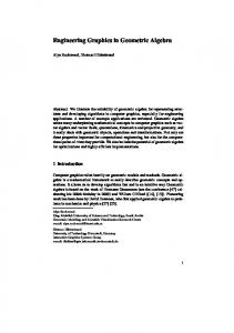
models. Students are asked to complete a range of
Three introductory courses in engineering and
assignments during the semester to develop their
technical graphics are offered within the Graphic
knowledge and skills in constraint-based CAD. Figures
Communications Program – one is open to any student
1 through 4 show some of the assignments that are used
at the university (GC120), one is for mechanical and
to develop and assess students in the introductory
aerospace engineering majors (GC211), and one is
courses.
designed for industrial engineering majors (GC210). The main goal of the introductory courses is to provide an orientation to the language of technical graphics. The courses help students develop and refine their ability to use this universal technical language within the context of the concurrent engineering design process as well as gain an understanding of how computer-aided design is used to create objects that
Figure 1. STOP BASE.
students use on a daily basis. Emphasis in the
133
report of the project. Figures 5 & 6 are examples of student projects.
Figure 2. DRYER CLIP.
Figure 5. Bicycle Axle.
Figure 3. PISTON CAP.
Figure 6. Dividers. III. Applied CAD & Geometric Controls The second course in the engineering and technical graphics series (GC350) was designed to give students direct exposure to and interaction with the evolving industrial use of computer-aided design and modeling. Students produce mid-level computer models of
Figure 4. TAILSTOCK CLAMP Detail Drawing.
individual parts and assemblies of parts that encompass For the final project, students are asked to select a
the full range of current CAD software capabilities
design that contains 3-5 parts that they must reverse
from 3-Dimensional feature-based solid modeling to an
engineer. Along with planning and documenting the
exploration of design for manufacture. Students apply
modeling strategies for each part through freehand
conventional tolerancing, geometric dimensioning and
sketching, students must model each part, create a
tolerancing, and technical documentation to a variety of
rendered assembly of the design, create a detail
standard and non-standard parts in the course.
drawing of one of the parts, and submit a technical
134
At the end of the course students should be able to perform all modeling activities included in the introductory course as well as the following activities: build design intent into a model based on specific parameters;
apply
conventional
tolerances
(limit
dimensions) and geometric tolerances to 3D models and
engineering
drawings;
create
multiple
configurations of a 3D model using design tables;
Figure 9. Design Table of Woodruff Key.
model objects that require sweeps and lofts; create a rapid prototype of a model using a 3D printer; and
The final project in the GC350 course involves
create an assembly drawing of a design which includes
creating a complete set of working drawings for a
a bill of materials. Figures 7 through 9 show examples
design. Students model all individual parts, create detail
of assignments used to develop and assess students in
drawings of non-standard parts (including applying
the GC350 course.
conventional tolerances to all mating parts and geometric dimensions to one part in the design), create an assembly drawing (which includes a bill of materials), and create a rendered assembly of the design. Figures 10 and 11 illustrate examples of final projects in this course.
Figure 10. CLAMP FIXTURE Assembly. Figure 7. TRIP LEVER Drawing and Model.
Figure 11. TOOL REST Assembly.
Figure 8. SLIDING DOOR GUIDE.
135
IV. Advanced CAD The capstone course in the engineering and technical graphics series (GC450) was designed to provide students with a culminating experience where they could apply their knowledge of computer-aided design. Students explore the theory and application of manufacturing databases developed with 3-D modeling tools. They also examine the development and management downstream
of
3-D
geometry
applications
such
and
investigate
as
analysis,
Figure 13. Carbide Lattern Design.
documentation, and prototyping. In addition to readings in the areas of modeler types and databases, curves and
The second large project in the course is a group
surfaces, constraint-based and parametric modeling,
project. As a class, students reverse engineer a small
mass properties, kinematic and dynamic analysis, finite
lawn mower engine (see Figures 14 and 15). The
element
control,
students determine logical divisions for groups (eg.
documentation, and modeling for manufacturing,
drive train, engine block, sheet metal parts, etc.) and
students complete two large projects. The first is a
then divide the modeling tasks equitably among group
flashlight design project where students research
members.
analysis,
computer-numerical
flashlights for a particular application, sketch multiple iterations of their designs, narrow the design down to one, model all parts using solid and surface modeling tools, render the design, and present their design to the class. Examples of designs from the course are shown in Figures 12 and 13.
Figure 14. Small Engine Assembly.
Figure 12. Handlebar Mounted Light.
136
An example of feedback to a student for the TRIP LEVER might be: “3/5 points. Sketches for CutExtrude2, Cut-Extrude3, & Cut-Extrude4 are missing dimensions.
Please
make corrections per these
comments and show the modified part to me in class Wednesday. There is no need to resubmit the part to the homework directory.” Some instructors will allow students to correct their models and resubmit them. Although this can make managing homework grades Figure 15. Drive Train Sub-Assembly.
and classroom activities more difficult, correcting existing models appears to be more valuable to students
V. Assessment Strategies
than just receiving comments and a grade.
A variety of assessment strategies are used
For the final projects in each course, students are
throughout the courses. Approximately 20 sections of
given a detailed rubric for how each part of the project
the introductory courses are taught each semester by at
will be evaluated. An example grading rubric for the
least 9 different instructors. Each has their own
final project in the introductory course is shown in
preference for how to evaluate assignments. Constraint-
Figure 16.
based modeling activities are evaluated electronically by the instructors. This may be done in a couple of different ways. Instructors may grade assignments in the lab with the students present or they may ask the student to submit their files to a server so the file can be graded in a remote location (in the office or at home). For most assignments, instructors will focus on a handful of items. Table 1 shows the items that the instructor examines for the TRIP LEVER (Figure 7). Table 1. Grading Rubric for the TRIP LEVER. Description Part dimensions are correct Part orientation is correct Spotfaced hole remains centered when depth of part is changed Slot remains centered size is changed 9.5 diameter hole remains centered on tab when tab depth is changed Total
Points 1 point 1 point 1 point 1 point 1 point 5 points Figure 16. Project Grading Rubric.
Feedback to a student might come in the form of an email or a print-out handed to the student in class.
137
VI. Discussion and Reflections
Baxter, D.H. (2003). Evaluating an automatic grading system for an introductory computer aided design course. Proceedings of the 58th Annual Midyear Conference of the Engineering Design Graphics Division of the American Society for Engineering Education, Scottsdale, Arizona, November 16-19, 2003.
Two of the biggest challenges to this point have been faculty training and instructional materials development. With new releases of the software coming out every year, faculty development must be a priority. Instructors have to understand the power of the
Baxter, D.H. & Guerci, M. J. (2003). Automating an introductory computer aided design course to improve student evaluation. Proceedings of the 2003 Annual Conference of the American Society for Engineering Education, Nashville, Tennessee, June 22-25, 2003.
constraint-based modeling tool to be able to make connections between it and the engineering graphics topics covered in the course. They also must be able to troubleshoot a wide range of problems that students run
Branoff, T. J., Wiebe, E. N, & Hartman, N. W. (2003). Integrating constraint-based CAD into an introductory engineering graphics course: Activities and grading strategies. Proceedings of the 2003 Annual Conference of the American Society for Engineering Education, Nashville, Tennessee, June 22-25, 2003.
into while creating models. The development of supporting instructional materials has also been a challenge. Revising materials for new releases can be time consuming, and creating materials that are acceptable to every instructor is
Demel, J. T., Meyers, F. D. & Harper, K. A. (2004). Developing a nationally normed test for engineering graphics-First pilot tests and results. Proceedings of the 2004 Annual Conference of the American Society for Engineering Education, Salt Lake City, Utah, June 2023, 2004.
almost impossible. The integration of constraint-based modeling into the Graphic Communications curriculum appears to be going well. Students taking the three course sequence
Elrod, D. & Stewart, M. D. (2004). Assessing student work in engineering graphics and visualization course. Proceedings of the 2004 Annual Conference of the American Society for Engineering Education, Salt Lake City, Utah, June 20-23, 2004.
in engineering and technical graphics typically major in mechanical and aerospace engineering or technology education. They are securing employment throughout the country in a variety of careers. Some recent
Kelley, D. (2001). Cooperative learning as a teaching methodology with engineering graphics. Proceedings of the 2001 Annual Conference of the American Society for Engineering Education, Albuquerque, New Mexico, June 24-27, 2001.
graduates are working for engineering firms where they use their knowledge of constraint-based CAD along with their engineering degree for firms such as Integrated
Industrial
Information,
Inc.,
FineLine
Prototyping, Inc., Boeing, and Raytheon Missile Systems. Others are using their degree in education to teach technology education and drafting courses in public schools in North Carolina.
VII. References Barr, R. E., Krueger, T. J. & Aanstoos, T. A. (2004). Results of an EDG student outcomes survey. Proceedings of the 2004 Annual Conference of the American Society for Engineering Education, Salt Lake City, Utah, June 20-23, 2004.
138


![[PDF] Visualization, Modeling, and Graphics for Engineering Design ...](https://m.moam.info/img/260x300/pdf-visualization-modeling-and-graphics-for-engine_6477394b097c474b228bd59b.jpg)