JOURNAL OF GEOPHYSICAL RESEARCH, VOL. XX, NO. X, PAGES XXXX-XXXX, 2000
Constraints on magma flux from displacements data at Merapi volcano, Java, Indonesia F. Beauducel and F.-H. Cornet Département de Sismologie, Institut de Physique du Globe de Paris, France.
E. Suhanto Volcanological Survey of Indonesia, Bandung, Indonesia.
T. Duquesnoy and M. Kasser Institut Géographique National, St-Mandé, France.
Abstract. The displacement field has been monitored in the vicinity of the crater rim at Mount Merapi (Indonesia) from 1993 to 1997. During this period the volcanic activity has been quasicontinuous with dome growth, explosions, and pyroclastic flows. We measured a nine-point network every year with the Global Positioning System static method. Interpretation of results is conducted with a three-dimensional elastostatic boundary elements code that takes into account topography, fractures, and complex magma source geometry. The inversion technique yields an estimate of the variation with time of the boundary conditions at the magma duct interface together with the probability associated with the best model. The Young's modulus of the equivalent continuum is found to be very low (of the order of 1 GPa), a feature which suggests that a viscoelastic behavior may be more appropriate for this rock mass, given the observed seismic velocities for the domain of interest. A striking compatibility is outlined between observed deformations and the rate of occurrence of multiphase seismic events, once the main fractures of the structure have been taken into consideration. This suggests that the summit elastic (or viscoelastic) deformation field is controlled by the magma flux within the duct rather than by magma pressure variations. In addition, a nonelastic displacement has been identified at the westernmost point of the network. This was considered critical for the stability of the summit structure, a concern whose validity has been verified a posteriori by the July 1998 explosion.
1. Introduction
(GPS) network that was installed and displacement results that were obtained during the five campaigns we carried out. A threedimensional model which takes into account the real topography, the magma conduit, and the summit fractures is proposed in order to discuss possible deformation sources that explain observed displacement data.
Some understanding of magma conduits in volcanoes can be retrieved from seismic tomography, gravity, or magnetic fields analysis. The study of quasistatic ground motion during periods of activity (displacements, tilt, and strain) also contributes to this understanding. Recent synthesis of volcano geodesy has been conducted by Dvorak and Dzurisin [1997], who conclude that analysis of geodetical results may yield estimates of magma supply rates, of the location of magma sources, and in some cases, of the size and shape of complex magma reservoirs. In this paper, we attempt to identify the stress boundary conditions within the summit inner conduit for Mount Merapi (2964 m), a young andesitic stratovolcano located on central Java, Indonesia. For the last few years, Merapi has experienced quasicontinuous extrusion of lava at its summit. This extrusion forms a dome that is continuously and partially destroyed by avalanches and pyroclastic flows [Tjetjep and Wittiri, 1996; Purbawinata et al., 1997]. After a review of recent activity at Merapi and of geological structural observations, we present the Global Positioning System
2.
Recent Activity
2.1. Dome Growth Since the 1961 eruption, magma production has been limited to the main horseshoe-shaped crater (see Figure 1). We focus here on the period that began in 1991. After being inactive for 5 years, a strong seismic crisis occurred in 1990, followed by the growth of a new dome in the main crater on January 20, 1992 (Figure 2). During the following years, andesitic magma, which may be almost completely degassed, was slowly extruded as an endogenous dome, with flow rates ranging from 5,000 to 200,000 m3 d–1. The dome shape varied steadily with time, from a perfect hemisphere at the beginning of eruption to a more complex geometry. The crater floor dips 35° to the southwest, and the dome flowed down into that direction, giving it an ovoid shape. From the vesiculous aspect of avalanche fragments we know that the dome core is viscous and incandescent [Berthommier, 1990]. The dome is almost continuously in a steadystate instability. Its slope reaches 60° in a few places, a feature which is evidence for a very
Copyright 2000 by the American Geophysical Union. Paper number 1999JB900368. 0148-0227/00/1999JB900368$09.00
1
2
BEAUDUCEL ET AL.: CONSTRAINTS ON MAGMA FLUX AT MERAPI Java Sea
5°
0°
6° S
Jakarta
-5°
100°
110°
120°
130°
7° S
8° S
BALI
Indian Ocean 106° E
Merapi
108° E
110° E
112° E
114° E
1954 1888
1948 1956
NUR NTR 1957
1883
Mati
PUN .D om e
MAR
1
1986-1991 Crater Floor
Gendol
GPS Benchmark
Ash Platform
100 m
30
Woro AYI 1883
961 ce 1
Crater Rim
19
sin
1957
Fracture Lava Flow Date and Limits
IPU
1940
l do en G F.
1934
1906
F
1992 Dome Center
1955
LUL
LIL
F. Lava 56
DOZ 1911-1913
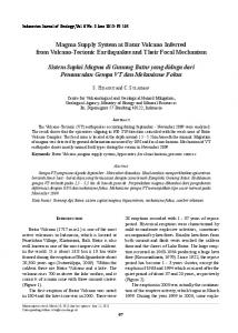
Figure 1. (top) Topography of Java Island. (bottom) Map of Merapi summit: location and name of Global Positioning System (GPS) benchmarks, craters, fractures, and lava flows. Approximate position of the 1992 dome center (compilation of base maps [Sadjiman, 1986, 1992; Ratdomopurbo, 1995]) is shown.
high friction angle. Consequently, dome growth is usually followed by gravitational rock avalanches. The period of interest for this paper was marked by four main dome collapses: April 18, 1993; November 22, 1994 (3.5 × 10⁶ m3); January 17, 1997 (1.3 × 10⁶ m3), and July 11-19, 1998 (unknown volume). Since 1993, the dome is monitored daily with a 1000-mm focal length camera with shots taken from the foot of the volcano [Ratdomopurbo, 1995]. This yields an estimate of the dome height with a roughly 0.2-m resolution and a 10% error on the volume, considering a perfect semispherical dome.
pressure variations. The “low-frequency” events are short tremors ~1.5 Hz and are very superficial. The “multiphase” events are complex and very shallow seisms. Shimozuru et al. [1969], followed by Ratdomopurbo [1995], gave some evidence for a link between the multiphase events and the magma production at the summit: They may result from shear stress variations within the viscous magma along the duct. The “guguran” events are associated with rock avalanches from the lava dome and reflect a combination of the dome stability and growth rate. Pyroclastic flows are also detected on seismograms, but they are usually confirmed by visual observation. 2.3. Geodetic Surveys A geodetic network has been installed by the Volcanological Survey of Indonesia and U. S. Geological Survey in 1988 for Electronic Distance Measurement (EDM) monitoring [Suganda et al., 1995; Purbawinata et al., 1997]. Figure 4 shows the horizontal displacements of the summit points for the 1988-1992 period (SEL held fixed), including extrusion of the 1992 lava dome. We observe six zones with different behavior: TRI (60 cm to the west); NUR and LIL (30 cm to the north); PUN and LUL (no displacement); MAR and IPU (20 cm to the east); GQ4 (15 cm to the south); DOZ and ALB (100 cm to the south). Strain between consecutive zones is of the order of 10–2 and implies some inelastic behavior. Suganda et al. [1995] tried to model these data with Mogi’s [1958] point source model. They finally concluded that fractures observed at the summit are major discontinuities in the structure and prohibit modeling by a simple elastic continuum. Moreover, vertical components of these data are not constrained enough for proposing a temptative quantitative interpretation model.
3.
Data Acquisition
3.1. GPS Network The GPS method offers a major advantage over the EDM: Measurements can be carried out during cloudy weather and do not require direct view between benchmarks. Our GPS network is
2.2. Seismic Activity Since the first analysis of seismic events at Merapi by Shimozuru et al. [1969], seismic events are counted daily and classified into six categories that reflect different types of internal or external phenomena (see Figure 3) [Ratdomopurbo, 1995; Ratdomopurbo and Suharno, 1997]. Data come from one of the seismological network stations (Pusunglondon, 700 m from summit) installed in 1982. Seismic events denominated “volcanotectonic” type A (source depth from 2 to 5 km below the summit) and type B (depth 2 km); VTB, shallow volcano-tectonic (depth < 1.5 km); LF, low frequency (1.5 Hz); MP, multiphase; GG, “guguran” associated with rock avalanches; NA, nuées ardentes. Gray lines represent time of GPS campaigns.
mostly based on the existing benchmarks of previous geodetic monitoring in order to permit direct comparison of the results in future monitoring. Benchmarks have been chosen to cover almost all the different lava flows at the summit. Table 3 gives positions and associated eruption period of the baserock. The network consists of 9 points at the summit, around the main crater, and 5 additional far-field points used as first-order network (Figure 5). The far-field network GPS processing for 1996 and 1997, including local meteorological modeling, have been presented and discussed by Beauducel and Cornet [1999]. GPS vertical displacements for 1993, 1994, and 1995 networks are also presented by Jousset et al. [2000]. We introduce here the summit data concerning the nine-points shown on Figure 1 from 1993 to 1997, whereas we investigate local phenomena located around the top part of the volcano. 3.2. GPS Measurements We measured the network every year from 1993 to 1997, using two Sercel NR101 single-frequency receivers, except in 1994 when we used three Ashtech dual-frequency receivers. The relatively short dimension of the network (8 km for the longest base-
Point Name PUN0 LUL0 MAR2 DOZ0 LIL0 NUR0 NTR0 IPU0 PUN0 LUL0 MAR2 DOZ0 AYI0 LIL0 NUR0 NTR0 IPU0 PUN0 LUL0 MAR2 DOZ0 AYI0 LIL0 NUR0 NTR0 IPU0
Table 2. GPS Campaigns Description Campaign Date September 19-21, 1993 September 24-26, 1994 September 26-29, 1995 October 25-December 13, 1996 March 15-26, 1997
Baselines 12 17 18 32 28
Free Degree 21 12 21 57 42
S.D. are average of the three component position errors after adjustment.
S.D., m 0.0087 0.0083 0.0040 0.0151 0.0173
PUN0 LUL0 MAR2 DOZ0 AYI0 LIL0 NUR0 NTR0 IPU0
Relative Displacements, m Errors σ, m East North Up dE dN dU September 1993 to September 1994 –0.000 –0.035 +0.019 0.017 0.008 0.030 –0.001 –0.018 +0.022 0.017 0.008 0.029 –0.010 –0.012 +0.015 0.021 0.010 0.038 –0.002 –0.026 –0.051 0.017 0.009 0.030 –0.012 –0.005 +0.039 0.020 0.009 0.036 +0.003 –0.006 +0.039 0.020 0.009 0.035 –0.013 +0.017 +0.050 0.019 0.010 0.034 –0.014 –0.019 +0.022 0.026 0.012 0.046 September 1994 to September 1995 –0.018 –0.009 –0.051 0.015 0.007 0.023 –0.015 +0.008 –0.034 0.015 0.007 0.023 –0.013 –0.006 +0.008 0.019 0.009 0.033 –0.019 –0.043 +0.012 0.016 0.008 0.025 –0.028 –0.013 +0.013 0.017 0.008 0.027 –0.007 +0.006 –0.030 0.019 0.008 0.031 –0.013 +0.019 –0.022 0.018 0.009 0.030 –0.016 +0.051 +0.052 0.018 0.009 0.028 –0.012 –0.002 +0.007 0.025 0.011 0.042 September 1995 to November 1996 +0.003 +0.007 +0.021 0.013 0.007 0.015 +0.007 +0.015 +0.035 0.012 0.006 0.014 +0.008 +0.017 +0.015 0.013 0.008 0.015 +0.021 –0.111 –0.055 0.014 0.009 0.018 +0.002 –0.002 +0.012 0.014 0.008 0.018 –0.000 +0.063 +0.045 0.014 0.008 0.017 +0.005 +0.070 +0.033 0.014 0.009 0.018 –0.112 +0.165 +0.021 0.014 0.008 0.017 +0.008 +0.013 +0.012 0.013 0.007 0.015 November 1996 to March 1997 –0.011 –0.011 –0.039 0.015 0.011 0.020 –0.011 +0.005 –0.033 0.014 0.009 0.019 –0.021 +0.006 –0.033 0.016 0.011 0.021 –0.003 +0.050 –0.042 0.019 0.014 0.026 –0.028 +0.012 –0.023 0.018 0.013 0.025 –0.002 –0.003 –0.035 0.017 0.011 0.023 +0.005 –0.006 –0.005 0.018 0.012 0.024 –0.024 +0.066 –0.019 0.019 0.012 0.025 –0.014 +0.013 –0.031 0.016 0.012 0.022
4
BEAUDUCEL ET AL.: CONSTRAINTS ON MAGMA FLUX AT MERAPI our case. The final positions of points for each period are obtained in local universal transverse Mercator (UTM) coordinates together with their a posteriori errors and the mean standard deviation of residues for the entire network adjustment (Table 2). Relative displacements are computed for the 4-year period by differences between positions, while uncertainties are obtained by a rootmean-square of positions errors (Table 1). 3.3. Displacements Results
Figure 4. Electronic distance measurement (EDM) network and horizontal displacements observed between 1988 and 1992, relative to SEL point [after Purbawinata et al., 1997]. Extension of the crater rim reaches > 1 m during this period. Most of the benchmarks have been used for the GPS network, except for ALB (has become inaccessible), TRI (replaced by NTR0) and GQ4 (replaced by AYI0).
sponds to n – m + 3x, where n is the number of data (three component per baseline), m is the number of unknown parameters (coordinates of points), and x is the number of fixed points. This parameter must be significantly >1, and it varies from 12 to 57 in
Cumulated displacements from 1993 to 1997 are presented in Figure 6 (for year-to-year displacement vectors, see also Figure 13). The summit deformation pattern is very similar to that shown by previous EDM results (direction and relative amplitudes), but amplitudes are 2 or 3 times smaller. This pattern can be analyzed quantitatively through four zones with different behaviors which are clearly observed (Figure 7 and 8): Point NTR0 with displacements up to 30 cm to the northwest (zone 1); points NUR0 and LIL0 with displacements up to 10 cm to the north (zone 2); all the points on the eastern part of the main crater (LUL0, PUN0, MAR2, IPU0 and AYI0) with displacements up to 5 cm toward the crater center (zone 3); and point DOZ0 with displacements up to 20 cm to the southeast (zone 4). These four zones are all separated by documented fractures. Thus we may consider that the fractures correspond to real discontinuities in the summit structure that may play an important role in this deformation field.
4.
Three-Dimensional Elastic Modeling
From a 3-D representation of the summit structures our numerical analysis attempts to model the deformation field induced by the flow of a viscous magma within a conduit. The material is considered as elastic, isotropic, and homogeneous, but it includes the main discontinuities deduced from the observed fractures at surface.
Table 3. Merapi GPS Network Points Description and Reference Coordinates Number
a b
Code
Name
140 150 160 130 120 110 160 170 180
DOZ0 AYI0 a IPU0 MAR2 LUL0 PUN0 LIL0 NUR0 NTR0
Dozy Ayik Ipung Sumarti Luluk Puncak Lilik Nurudin New Tri
100 090 085 105 107
JRA0 a BAB0 b DEL1 b SEL0 a PUS0
Jrakah post Babadan post Deles station Selokopo Atas Pusunglondon
These are for September 1994 position. These are for November 1996 position.
Coordinates UTM-49 WGS84, m Associated Eruption Date Eastern Northern Elevation Summit Network 1911-1913 438,914.3906 9,166,220.3632 2893.7927 1883 439,032.0146 9,166,319.4572 2927.8508 1883 439,039.7631 9,166,409.5919 2949.6553 1906 439,059.7015 9,166,443.4495 2949.9093 1955 438,978.0801 9,166,537.5288 2976.7699 1948 438,956.0607 9,166,470.4427 2986.7342 1956 438,906.1561 9,166,508.9948 2971.4667 1948 438,854.8539 9,166,549.0580 2953.1621 1957 438,755.1067 9,166,509.1514 2927.3755 First-Order Network Merbabu volcano 436,180.2839 9,171,235.4989 1335.4256 Old-Merapi 434,975.8720 9,168,041.1995 1321.0498 Mid-Merapi 440,692.1316 9,163,972.9254 1511.4785 Mid-Merapi 439,543.9644 9,167,528.3135 2570.4127 Mid-Merapi 439,552.3159 9,166,838.7151 2734.0062
BEAUDUCEL ET AL.: CONSTRAINTS ON MAGMA FLUX AT MERAPI ∂w τ = −µ . ∂r r = a
5 (3)
The pressure in the duct (2) is theoretically dependent on the shear stress variations (3), and it must vary with depth along the conduit. We do not consider here the vertical gradient of pressure but a mean value for pressure variations, which is sufficient for the study of resulting surface deformations. 4.2. Mixed Boundary Elements Method (MBEM) The deformation pattern and topography of the Merapi summit cannot be properly modeled with a one- or two-dimensional modeling. Moreover, we have to take into account a discontinuous medium with fractures. The MBEM [Cayol and Cornet, 1997] is well adapted to model small elastic perturbations in a three-dimensional homogeneous body [Cayol and Cornet, 1998; Beauducel and Cornet, 1999]. The method combines two different boundary elements methods: the direct method [Rizzo, 1967; Figure 5. Merapi GPS network and example of baselines pattern measured in March 1997.
4.1. Structures and Sources Involved The various observations described in section 2 yield an outline of the phenomenology involved in the summit deformations. Since there has been a continuous production of viscous lava dome into the main crater for some 10 years, we suppose the existence of a unique magma conduit located at the center of the 1992 new dome hemisphere (see Figure 2). Three main fractures have been identified at the volcano summit from geomorphological observations [Sadjiman, 1986, 1992]. Figure 1 shows their approximate positions over the 1986 topography. At ground surface all the fractures are subvertical and produce hot gases, essentially water vapor and SO2, suggesting that they may be connected to the magma. For the modeling their vertical extension has been chosen equal to their horizontal extension. Unfortunately, no extensometric data are available, except for the “Lava 1956” (near benchmark LIL), which has been monitored manually from 1991 to 1993 by the Merapi Volcano Observatory. A differential opening equal to 5 cm has been observed during this period and is taken as evidence for the activity of this fracture (Subandriyo, personal communication, 1993). Two types of material are involved: (1) hot and viscous lava behaving as a fluid (density ρa and viscosity µ); and (2) cold and fractured rock behaving as a elastic solid (density ρr, Young modulus E, and Poisson ratio ν) . Its boundary is associated with the topography and magma conduit before the 1992 eruption. Following this hypothesis, we consider three types of deformation sources (see Figure 9): (1) dome weight effect on the crater floor, as a function of the dome height h, P(h) = ρagh ; (1) (2) magma pressure in the duct, as a function of pressure in the magma chamber Pc and maximum dome height variations, P = Pc + ρaghmax ; (2) (3) wall shear stress along the duct of radius a due to the drag associated with viscous magma flow (Newtonian fluid with velocity w),
Figure 6. Cumulated displacements of GPS points from 1993 to 1997 and 1993 summit map. (a) horizontal view; (b) perspective view in a vertical plan (azimuth N145° E, elevation 0°), such that vertical displacements scale is respected.
6
BEAUDUCEL ET AL.: CONSTRAINTS ON MAGMA FLUX AT MERAPI
2
1 F. Lava 56
F. Dome 1
3
Conduit
F. Gendol
20 cm
4
Figure 7. Pattern of summit horizontal displacements 1993 to 1997. The arrows show four zones with different behavior separated by fractures. Thick gray lines show fractures and magma conduit surface locations, and thin gray line show approximate crater rim, the dots represent GPS benchmarks.
Lachat and Watson, 1976] and the displacements discontinuity (DD) method [Crouch, 1976]. The direct method is based on Betti’s reciprocal theorem and the solution of Kelvin’s problem of a point force in an infinite body. It is well suited for modeling topography and cavities. The DD method is based on the analytical solution of a single displacement discontinuity in an infinite space [Rongved and Hill, 1957]. It is well suited for modeling fractures. This allows us to consider free topographic surfaces, magma conduits, and fractures. Any stress component (pressure and shear) can be introduced on the elements associated with the direct method. For fractures (DD) the code does not yet include friction, and fracture boundaries are free to interpenetrate. This is consistent with a reality where superficial fractures are already open but may undergo normal or tangential motion, yet without any significant contact.
a lower Young modulus, this pattern does not agree with our GPS data for the same period of time. Moreover, this period corresponds to a quite large dome volume variation (2.6 × 10⁶ m3). We conclude that dome weight variations on the crater floor have a negligible effect on displacements. 4.4. Pressure and Wall Shear Stress In order to analyze the effect of pressure and shear stress sources, the geometry of the magma conduit must be known. From the results of previous study conducted by Ratdomopurbo [1995] we choose a vertical 25-m radius cylindrical conduit, with a 450-m depth, in order to avoid effect from the bottom boundary. Because we do not know a priori the respective amplitudes for both sources, we will consider normalized pressure P/E and shear stress τ/E. Our arbitrary unit of displacement will be equal, for instance, to 1 mm for a 1-MPa source and a 30-GPa Young’s modulus. For a given structure the displacement field for both sources is computed separately: u(P) and u(τ). Because of the elastic hypothesis the complete displacement field can be computed then by the linear combination: u(P,τ) = αu(P) + βu(τ). 4.4.1. Structure without fracture. Results of the first computation of the two sources effects on a continuous medium are presented in Figure 12. With a pressure source, displacements are almost horizontal, and we notice that amplitudes decrease rapidly with distance from the source, becoming negligible on the crater rim. On the contrary, with a shear stress source, displacements amplitudes are large over the whole surface, even far from the conduit. For both sources, effects of the asymmetric topography are obvious, and the displacement directions are closer to the GPS data than for dome weight source.
4.3. Dome Weight Effect The deformation induced by the dome weight depends strongly on its shape and on the real topography of the crater floor. A very good estimation of the complete 3-D dome geometry has been computed for the 1993 and 1994 periods [Jousset et al., 2000], but these data unfortunately do not exist for the 1995 to 1997 period. Considering that the lava dome core behaves as a fluid, we computed the height difference between the 1993 and 1994 domes (Figure 10a) and determined the pressure variation on each element of the crater floor by ∆P94–93 = ρag(h94 – h93) . (4) We choose the lava density ρa = 2,400 kg m–3 [Jousset, 1996], the Young modulus E = 30 Gpa, and Poisson ratio ν = 0.25. Results are presented on Figure 10b. Displacement field at GPS points is mainly downward with an average amplitude equal to 0.3 cm. Horizontal displacements are almost in the same northeast direction, owing to the crater floor slope. Even if we choose
Figure 8. Relative displacements from 1993 to 1997 for each component and corresponding zone number.
BEAUDUCEL ET AL.: CONSTRAINTS ON MAGMA FLUX AT MERAPI
Viscous Dome (ρa, µ)
hmax P(h) P Fracture w
Elastic Medium (ρr, E, ν) τ
z r Figure 9. Schematic representation of the different types of source involved in our 3-D model: dome weight effect on the crater floor, magma pressure in the duct, and wall shear stress due to the flux variation of a viscous fluid.
4.4.2. Structure with fractures. The meshing of the fractures has required particular attention. We introduced progressively the three known fractures into the structure in order to analyze their respective effects on the displacement field. The Gendol fracture (see Figure 7 for fracture names) is the most important one because it is radial to the conduit and is supposed to reach it. Pressure variation into the duct will produce an opening of this fracture and a displacement of zone 4 to the south, as was observed. When introducing the lava 56 fracture, the model in-
7
dicates that the fracture is subjected to a dextral shear, thus zone 1 moves to the east. Zone 2 is also affected by this movement. Because this is not compatible with observations, we decided to consider only the east portion of the lava 56 fracture. Introduction of the dome 1 fracture produced an attenuation of the zone 3 displacements . Final configuration is made of the three fractures Gendol (radial to conduit, N135°E, depth = length = 250 m), dome 1 (N135°E, depth = length = 200 m), and east part of lava 56 (N90°E, depth = 250 m, length = 100 m). Results for the two sources effects are presented in Figure 11. The displacement pattern seems to be compatible with our observations, and we keep this configuration in order to obtain the best fit to the data. 4.5. Inverse Problem For determining the two parameters (pressure and shear stress) from the available data set we explored the model space for each of the four time periods. Each inversion process concerns 9 times 3 components of relative displacements with their uncertainties (data) and 2 parameters (α and β). The forward problem corresponds to a linear combination of the two different sources. A least squares misfit function is defined, and we search for its minimum. Systematic exploration of the model space provides means to identify the real minimum misfit and to determine the probability for each model parameter. Comparison between computed and observed horizontal displacements is presented in Figure 13: (1) For zone 1 (NTR), computed displacements are systematically smaller in amplitude and ~30° eastward compared to the data for 1993 to 1996 period. For 1996 to 1997, orientation is reversed. For zone 2 (NUR and LIL), amplitudes and directions are correct from 1993 to 1997. For zone 3 (LUL, PUN, MAR, IPU and AYI), amplitudes are correct except for PUN on 1993 to 1995 period and for AYI for 1994 to 1995 period. For zone 4 (DOZ), amplitudes and directions are correct from 1993 to 1997.
Figure 10. (a) Dome height difference between 1993 and 1994. Black dots are GPS benchmarks. (b) Displacements field due to 1993 to 1994 dome height difference (thin arrows). Heavy arrows represent displacements at GPS benchmarks position (different scale).
8
BEAUDUCEL ET AL.: CONSTRAINTS ON MAGMA FLUX AT MERAPI
Figure 12. Displacement field computed without fracture in the medium. (a) Pressure source. (b) Wall shear stress source. Thick arrows stand for blowup displacements at GPS benchmarks position (different scale).
Results of the four inversion processes correspond to the temporal evolution of the two parameters: Pressure (see Figure 14) and shear stress along the duct (see Figure 15). They will be compared now to other observations.
5.
Discussion
5.1. Structure Behavior
The good agreement between the model and the data supports the hypothesis that the summit structure exhibits an elastic behavior and that preexisting fractures are significant and have been well localized. However, the large misfit for zone 1 implies that these displacements cannot be explained by the elastic model we considered. We concluded that this zone did not exhibit an elastic behavior and suggested that it presented a potential rock slope problem [Beauducel, 1998; Beauducel et al., 1998]. However,
Figure 11. Displacement field computed with three fractures in the structure. (a) Pressure source. (b) Wall shear stress source. Thick arrows stand for blowup displacements at GPS benchmarks position (different scale).
BEAUDUCEL ET AL.: CONSTRAINTS ON MAGMA FLUX AT MERAPI
9
Figure 13. Comparison of observed (heavy arrows) and computed (light arrows) displacement vectors with associated ellipsoid 68% confidence level. Crater rim and fractures are represented as black lines. (a) 1993 to 1994. (b) 1994 to 1995. (c) 1995 to 1996. (d) 1996 to 1997.
because there was only one benchmark on this zone, the potential volume of rock that would collapse to the northwest direction could not be estimated. Interestingly, this zone effectively collapsed in July 1998, producing some 5-km-long pyroclastic flows to the west (M.A. Purbawinata, public communication, 1998). 5.2. Pressure Variations As was mentioned above, pressure variations in the duct result from the sum of two phenomena: Lava column weight and deep magma chamber pressure. If the system is at equilibrium, the pressure in the upper part of the duct must be compensated by the dome weight. If this is not the case, the magma will flow out (the excess pressure is balanced by the shear stress) or the dome will explode. We compare in Figure 14 the evolution of computed pressure variations and the dome volume variations estimated at the same time as that of GPS campaigns. No correlation between the two data sets is observed. The pressure increases slowly until
1996, then decreases after January 1997, while the dome volume keeps increasing during the 1996-1997 period despite the dome explosion. It may be proposed that because of the explosion the 1995 to 1996 period was critical for the dome pressure equilibrium. A very significant magma production occurred during this period, and the dome shape was fairly axisymmetrical, so that for this period the magma pressure may be related to the dome height. With this hypothesis we are able to estimate the Young’s modulus from the dome height (150 ± 50 m) and the computed normalized (adimensional) pressure: E=
ρ a gh96 = 0.7 ± 0.2 GPa . P96
(5)
This value is very small as compared to that obtained from the observed seismic velocities, i.e., E = 25 GPa [Ratdomopurbo, 1992]. Because the summit structure is essentially constituted of uncompacted rock, fractured lava blocks, and ash matrix breccia,
10
BEAUDUCEL ET AL.: CONSTRAINTS ON MAGMA FLUX AT MERAPI
6 4
ated with the magma flux may be, in fact, the significant source of deformation, rather than variations in magma pressure.
Normalized Pressure Variation (10–3)
2
6.
0 -2
1995
1996
1997
1996
1997
3 2
Dome Volume (106 m3)
1 0 -1 -2
1995
Figure 14. Relation between the computed pressure variation and the observed dome volume variation at the times of GPS measurements.
this low modulus may reflect a viscoelastic behavior of the largescale equivalent continuum. 5.3. Wall Shear Stress We present in Figure 15 the computed normalized wall shear stress variations and the variation of the rate of occurrence of multiphase seismic events at the time of GPS campaigns. The correlation is quite striking for the whole period 1993 to 1997. We take it to conclude that displacements observed near the crater rim contain information on the magma flux in the duct if, indeed, the multiphase events are caused by release of the shear stress associated with the viscous drag within the magma, as proposed by Shimozuru et al. [1969]. From the estimation of Young’s modulus the magnitude of relative shear stress variations can be computed. Values range from –0.19 to +0.13 MPa. From (3) and estimation of the Merapi magma viscosity µ = 107 Pa s [Ratdomopurbo, 1995] the relative instantaneous velocity (i.e., values at the time of the GPS campaigns) is found to vary from –0.475 to +0.325 m s–1. Figure 16 shows the mean magma flux evaluated from the dome growth observed from 1993 to 1997. It is of the same order of magnitude, i.e., 0.5 m s–1, for the periods of interest. 5.4. Volcanological Inferences Modeling the eruptive phenomena requires the introduction of boundary conditions and physical properties of involved materials. Our study indicates that a model with realistic structures effectively helps describing some of these characteristics. The values for elastic parameter and magma viscosity that are implied by this investigation differ significantly from laboratory measurements. This may be considered as one of the interesting outcomes from this kind of investigation since it provides an in situ evaluation for these parameters. At Soufriere Hills volcano, Montserrat, a remarkable correlation between tilts and seismicity has been observed during magma extrusion [Voight et al., 1998]. It has been interpreted as cyclic pressure variations in the upper part of the duct because of magma degassing. We propose here that the shear stress associ-
Conclusions
A three-dimensional elastic model has been proposed for the interpretation of the displacement field at the summit of Merapi volcano. It takes into account vertical fractures observed on the site. This model has outlined the existence of a nonelastic zone, which was considered likely to become a site of instability. This proposition has been validated a posteriori by the July 1998 explosion. The source of deformation has been interpreted with a two-parameter model (fractures location and geometry have been introduced a priori) which includes the magma pressure and the axial viscous drag along the duct. A strong connection has been established between the magnitude of the computed viscous drag and the rate of occurrence of multiphase seismic events, a feature consistent with the proposition of Shimozuru et al. [1969] that multiphase events reflect the release of shear within the magma while flux variations occur. Finally, a very low value has been estimated for the Young’s modulus in order to fit the displacement field associated with the January 1997 explosion. This suggests that a viscoelastic behavior may be more appropriate for the equivalent continuum, given the dynamic Young’s modulus estimated from wave propagation. Acknowledgments. This work was supported by Délégation aux Risques Majeurs (French Department of Environment) and Volcanological Survey of Indonesia in the framework of the French-Indonesian cooperation in volcanology. We are very grateful to W.S. Tjetjep, R. Sukhyar, I. Bahar, M.A. Purbawinata, Surono, G. Poupinet, and M. Diament for their continuous support. For their participation in GPS campaigns and great help in the field we thank very much Merapi Volcano Observatory and Volcanological Survey of Indonesia teams, and B. Voight, K. Young, C. Courteille, P. Jousset, J. Tondeur, and especially J. Guilbert and M. Dejean from French Embassy of Jakarta. Special thanks to B. Sadjiman for providing us his maps of summit, A. Ratdomopurbo for the seismic and dome data, and P. Jousset and J. Zlotnicki for digitizing some of the data. The authors would like to thank the reviewers M. Lisowski, A. Jolly, and A. Linde for very constructive comments. There is also a “Pre-Erupt” EC projet (ENV4-CT96-0259) contribution and 3 2 1
Normalized Wall Shear Stress (10–4)
0 -1 -2 -3
1995
1996
1997
1996
1997
8 6 4
Multiphase Seisms Variation (103)
2 0 -2 -4 -6
1995
Figure 15. Relation between the computed wall shear stress variation and the variations in the number of observed multiphase seisms at the times of GPS measurements.
BEAUDUCEL ET AL.: CONSTRAINTS ON MAGMA FLUX AT MERAPI 2 1.5
Magma flux (m.s–1)
1 0.5 0 1994
1995
1996
1997
Figure 16. Magma flux deduced from dome volume variations.
IPGP #1660.
References Beauducel, F., Structures mechanical behaviour of Merapi volcano, Java: A methodological approach of the deformation field, thèse de doctorat, 260 pp., Univ. Denis Diderot Paris VII, Paris, 1998. Beauducel, F., and F.H. Cornet, Collection and three-dimensional modeling of GPS and tilt data at Merapi volcano, J. Geophys. Res., 104, 725-736, 1999. Beauducel, F., F.H. Cornet, and W.S. Tjetjep, Constraints from GPS and tilt data on the magma flux at Merapi volcano, Java, paper presented at XXIII General Assembly, Eur. Geophys. Soc., Nice, France, April 20-24, 1998. Berthommier, P.C., Étude volcanologique du Merapi: Téphro-stratigraphie et chronologie, produits éruptifs, thèse de doctorat, 180 pp., Univ. Blaise Pascal, Clermont-Ferrand II, Clermont-Ferrand, 1990. Cayol, V., and F.H. Cornet, 3-D mixed boundary elements for elastostatic deformation field analysis, Int. J. Rock Mech. Min. Sci., 34, 275-287, 1997. Cayol, V., and F.H. Cornet, Three-dimensional modeling of the 19831984 eruption at Piton de la Fournaise volcano, Réunion Island, J. Geophys. Res., 103, 18,025-18,037, 1998. Crouch, S.L., Solution of plane elasticity problems by the displacement discontinuity method, Int. J. Numer. Methods Eng., 10, 301-343, 1976. Dvorak, J.J., and D. Dzurisin, Volcano geodesy: The search for magma reservoirs and the formation of eruptive vents, Rev. Geophys., 35, 343-384, 1997. Jousset, P., Microgravimétrie et gravimétrie en volcanologie: Méthodologie et application au volcan Merapi, thèse de doctorat, 225 pp., Univ. Denis Diderot Paris VII, Paris, 1996. Jousset, P., S. Dwipa, F. Beauducel, T. Duquesnoy, and M. Diament, Temporal gravity at Merapi during the 1993-1995 crisis: an insight into the dynamical behavior of volcanoes, J. Volcanol. Geotherm. Res., in press, 2000. Lachat, J.C., and J.O. Watson, Effective numerical treatment of boundary
11
integral equations: a formulation for three dimensional elastostatics, Int. J. Numer. Meth. Eng., 24, 991-1005, 1976. Mogi, K., Relations between the eruptions of various volcanoes and the deformations of the ground surfaces around them, Bull. Earthquake Res. Inst. Univ. Tokyo, 36, 99-134, 1958. Purbawinata, M.A., A. Ratdomopurbo, I.K. Sinulingga, S. Sumarti, and Suharno, Merapi Volcano: A Guide Book, Dir. Vulkanol., Bandung, Indonesia, 1997. Ratdomopurbo, A., Étude de séismes de type-A du volcan Merapi (Indonésie), diplôme d’études approfondies, 60 pp., Univ. Joseph Fourier Grenoble I, Grenoble, France, 1992. Ratdomopurbo, A., Étude sismologique du volcan Merapi et formation du dôme de 1994, thèse de doctorat, 208 pp., Univ. Joseph Fourier Grenoble I, Grenoble, France, 1995. Ratdomopurbo, A., and Suharno, Seismicity before, during and after the January 17, 1997 eruption of the Merapi volcano, paper presented at Merapi Volcano Decade International Workshop II, United Nations Educ., Sci. and Cult. Org., VSI, Yogyakarta, Indonesia, Dec. 1997. Rizzo, F.J., An integrated equation approach to boundary value problems of classical elastostatics, Q. Appl. Math., 25, 83, 1967. Rongved, L., and N.J. Hill, Dislocation over a bounded plane area in an infinite solid, J. Appl. Mech., 24, 253-254, 1957. Sadjiman, Peta situasi puncak Gunung Merapi, 1:1,000, Merapi Volcano Observatory, Yogyakarta, Indonesia, 1986. Sadjiman, Pola perkembangan rekahan di puncak Gunung Merapi 1992, perubahan morfologi kubah lava dan lokasi reflektor, Merapi Volcano Observatory, Yogyakarta, Indonesia, 1992. Shimozuru, D., T. Miyazaki, N. Gyoda, and J. Matahelumual, Seismic observation at Merapi volcano, Bull. Earthquake Res. Inst. Univ. Tokyo, 47, 969-990, 1969. Suganda, O.K., K. Ishihara, B. Voight, K.D. Young and Subandriyo, Strain components changes in association with the 1992 eruption of Merapi volcano, Indonesia, paper presented at Merapi Volcano Decade International Workshop, United Nations Educ., Sci. and Cult. Org., VSI, Yogyakarta, Oct. 1995. Tjetjep, W.S., and S.R. Wittiri, 75 Tahun Penyelidikan Gunungapi di Indonesia, Dir. Vulkanol., Bandung, Indonesia, 1996. Voight, B., R.P. Hoblitt, A.B. Clarke, A.B. Lockhart, A.D. Miller, L. Lynch, and J. McMahon, Remarkable cyclic ground deformation monitored in real-time on Monserrat, and its use in eruption forecasting, Geophys. Res. Lett., 25, 3405-3408, 1998. __________________ F. Beauducel and F.H. Cornet, Département de Sismologie UMR 7580 CNRS, Institut de Physique du Globe de Paris, 4 place Jussieu, Case 89, 75252 Paris Cedex 05, France. (
[email protected];
[email protected]). E. Suhanto, Volcanological Survey of Indonesia, Jalan Diponegoro No 57, Bandung 40122, Indonesia. (
[email protected]). T. Duquesnoy and M. Kasser, Institut Géopgraphique National, 2 avenue Pasteur, BP 68, 94160 Saint-Mandé, France. (
[email protected];
[email protected]).
(Received January 4, 1999; revised August 11, 1999; accepted October 13, 1999)
12
BEAUDUCEL ET AL.: CONSTRAINTS ON MAGMA FLUX AT MERAPI