International Journal on Advances in Telecommunications, vol 11 no 1 & 2, year 2018, http://www.iariajournals.org/telecommunications/
65
Context Aware Control Schemes for the Performance Improvement of V2X Network Slices
Alexandros Kaloxylos
Prajwal Keshavamurthy, Panagiotis Spapis, Chan Zhou
Department of Informatics and Telecommunications University of Peloponnese Tripoli, Greece email:
[email protected]
Huawei German Research Center Munich, Germany email:
[email protected] [email protected] [email protected]
Abstract— Network slicing for 5th Generation (5G) networks enables the support of multiple logical networks, called slices, which aim to be tailor-cut network solutions for specific services for the vertical industries (e.g., transportation, smart factories, health industry etc.). Although, considerable effort has been taken to define the generic framework for network slices, it still remains open how the network performance can be further optimized by taking into consideration the specificities of each use case. At the same time, the work for the specification of network functions to support autonomous driving is picking up speed. However, up to this moment, it is still not addressed how contextual information can serve the optimization of a vehicle-to-everything (V2X) slice. This paper provides in detail the latest status of the 3GPP standardization process related to slicing. It also introduces two new mechanisms called Context Enhanced MOBility management (CEMOB) and Context-Aware Resource Pre-allocation (CARP). The former improves the existing mobility management process while the latter serves the minimization of the communication delay among vehicles. The point we make with these two mechanisms is that by taking advantage of contextual information the performance of network control functions can be significantly improved. Towards this end, we quantify the merits of our mechanisms and we present how these are integrated into a V2X slice. Keywords-network slicing; mobility management; allocation of resources; V2X communications.
pre-
I. INTRODUCTION Using contextual information for future mobile networks has become lately a hot topic [1]. 5G networks target, apart from the support of the telecommunications sector, also the communication needs of “vertical industries” like autonomous driving in transportation, smart factories, new health services, etc. An extensive list of 5G use cases can be found in [2] and [3]. A thorough examination of the verticals has identified that these sectors have diverse requirements. These requirements are mapped to different network Key Performance Indicators (KPIs). The KPIs indicatively include throughput, transmission reliability, latency, energy consumption, blocking probability, etc. Services and applications for the vertical industries have different requirements and thus, different values for the
aforementioned KPIs. It is widely accepted that no single network can support efficiently all these different use cases. Thus, it appears that the deployment of parallel logical networks over the same network infrastructure is a necessity. These logical networks may have network functions (NFs) configured differently or even introduce new network functions both in the Radio Access Network (RAN) [4] as well as the Core Network (CN) [5]. The 3rd Generation Partnership Project (3GPP) has defined a network slice to be “ A logical network that provides specific network capabilities and network characteristics” [6]. A “Network Slice” is implemented by a “slice instance” that in its turn is created by a “network slice template”. The latter is a template that defines a complete logical network including the NFs, their interfaces and their corresponding resources. Network slicing has been intensively investigated during the past years both by industry and academia. There are several research proposals that target full flexibility in terms of selecting, organizing and deploying NFs [7]. At the same time, 3GPP has already delivered the first phase specifications for 5G networks that include also the support for slicing. The standardization activities have followed a sensible path and have re-used existing NFs or share NFs across different slices as much as possible, focusing essentially on the enhanced Mobile BroadBand (eMBB) slice. The use cases to be supported, as well as their requirements, have been thoroughly studied [8], but current specifications do not provide fully tailor-cut solutions for them. In order to do this, it is needed to work really closely with the representatives of the so called “vertical industries” (e.g., transportation, health, factories, energy). This is needed to understand not only the requirements and the operational environment, but also the contextual information produced and how this can be used to optimize network functions. For example, the newly founded 5G Automotive Association (5GAA) [9] is working towards such a direction. Still, the activities for proposing mechanisms driven by such organizations, that are expected to affect the standardization process, are in primitive steps. In the current paper, extending our previous work presented in [1], we present the latest status of the standardization activities related to network slicing. We also
2018, © Copyright by authors, Published under agreement with IARIA - www.iaria.org
International Journal on Advances in Telecommunications, vol 11 no 1 & 2, year 2018, http://www.iariajournals.org/telecommunications/
66 provide two novel mechanisms for vehicular communications, which can be easily deployed using slicing solutions. The first one is a new mobility management mechanism for autonomously driven vehicles. It takes advantage of contextual information that is possible to be used by the standardized 5G NFs. The second is a resource pre-allocation scheme that uses available contextual information to meet the stringent requirements of certain V2X use cases, by minimizing the communication delay among vehicles. These are exemplary schemes to highlight that different use cases need very different solutions. Thus, we believe that it is important that solution providers take into consideration the specificities of each use case. We also present how the new mechanisms can be supported by 5G networks. The rest of the paper is organized as follows. In Section II, we provide the latest status of 3GPP in relation to slicing. Section III discusses how mobility management is planned to be supported in the technical specifications and why we consider this not to be efficient for moving vehicles. In Section IV, we provide the details of CEMOB on how to extend the 5G network functions to improve mobility management for moving vehicles. In Section V, we present quantitative results that illustrate the benefits of our scheme. In Section VI, we discuss how the allocation of resources takes place in 5G networks and what is the expected delay, while in Section VII we present the CARP mechanism, that minimizes the communication delay among vehicles and we analyse its performance improvements. In Section VIII, we summarize the key findings of the paper. Finally, Section IX concludes the paper and describes future directions. II.
SLICE SUPPORT IN 3GPP
3GPP has decided to treat 5G specifications in two phases. The first one is just recently completed (Release 15). This phase addresses a more urgent subset of the commercial needs. Phase 2 is to be completed by March 2020 (Release 16) for the IMT 2020 submission, having addressed all identified use cases & requirements. In relation to slicing, several working groups are currently progressing on the key elements and procedures that have to be specified. In [6] and [10], the 5G network architecture is presented. There, a list of technical key issues, as well as potential solutions for slicing are presented. For example, in these documents the issues of slice selection, slice isolation, sharing of NFs among slices, multi-slice connectivity, management of slices, etc. are being addressed. The first set of specifications has addressed a number of key principles. The first principle is that NFs, previously incorporated into monolithic network components, are now decomposed to smaller modules. The target is to allow a synthesis and configuration of the NFs on a per slice type basis. A second principle is the further splitting of user and control plane functions to facilitate a more flexible evolution of NFs. A third key principle is the exposure of NFs to external services through appropriate APIs. This is expected to allow a better collaboration among network operators and service providers.
Figure 1 presents a summary of the supported NFs. The control plane functions in the CN are considered to be the following: - Unified Data Management (UDM): supports the Authentication Credential Repository and Processing Function (ARPF). - Authentication Server Function (AUSF): supports the authentication of end users - Policy Control function (PCF): supports unified policy framework to govern network behaviour and provides policy rules to control plane functions - Core Access and Mobility Management Function (AMF): supports mobility management, access authentication and authorization, security anchor functions and context management - Session Management Function (SMF). supports session management, selection and control of UP functions, downlink data notification and roaming - User Plane Function (UPF): is the anchor point for inter/intra RAT mobility, supports packet routing and forwarding, QoS handling for user plane, packet inspection and policy rule enforcement - Network Exposure Function (NEF): provides a means to securely exchange information between services and 3GPP NFs. - NF Repository Function (NRF): maintains the deployed NF Instance information when deploying/updating/removing NF instances - Network Slice Selection Function (NSSF): supports the functionality to bind a UE with a specific slice. AF
Common functions
NG-5 NG-CP
AUSF
NG-1 UE
PCF
NRF
NEF
AMF
NSSF
SMF
NG-4
NG-2 NG-RAN
Slice dedicated functions
UDM
NG-3
NG-UP
NG-6
Data network
Figure 1: 5G service based architecture (adapted from [6])
Note that some of these functions are common for all slices, while others can be dedicated for different slices. A User Equipment (UE) may access multiple slices concurrently via a single RAN. For such cases, it is assumed that the involved slices should share some control plane functions, like the AMF. The abovementioned logical network allows the support of Application Functions (AF) and provides connectivity to typical external data networks. Moreover, it has been agreed that RAN will be sliceaware so as to treat slice traffic according to the customer needs. Moreover, RAN shall support resource isolation among slices so as to avoid shortage of shared resources in
2018, © Copyright by authors, Published under agreement with IARIA - www.iaria.org
International Journal on Advances in Telecommunications, vol 11 no 1 & 2, year 2018, http://www.iariajournals.org/telecommunications/
67 one slice to break the service level agreement on another [11]. Detailed alternative solutions have been proposed on how RAN is involved in slice selection by passing an appropriate identifier to the core network elements. Currently, slicing for RAN essentially focuses on different scheduling schemes for various slices and also by providing different L1/L2 configurations. Moreover, it is considered that even if a UE is connected to multiple slices, a single Radio Resource and Control (RRC) entity will be used. Other radio access protocols (i.e., Packet Data Convergence Protocol – PDCP and Radio Link Control - RLC) can used on a per slice basis. Every slice is identified by a Single Network Slice Selection Assistance Information (S-NSSAI) identifier. This identifier consists of a Slice/Service Type (SST) and a Slice Differentiator (SD). The former defines essentially the features and network services to be offered by a slice, while the latter is used to select among different slices of the same type. Currently, only 3 SST values have been agreed to be supported. These are a) eMBB, b) Massive Internet of Things (MIoT), and c) Ultra Reliable Low Latency Communications (URLLC) [6]. This information is exchanged as part of non-access stratum signalling through the RAN. In [12], the life cycle of a network slice is described by the following phases: a) Preparation phase, b) Instantiation, Configuration and Activation phase, c) Run-time phase and d) Decommissioning phase. Overall, 3GPP has defined the framework for slice deployment, operation and selection. However, there are no detailed solutions about how each slice type will be different from another. This is crucial gap that has to be addressed. In order to achieve the desired performance for each slice, new mechanisms are needed. These mechanisms must take advantage of the characteristics and the environment where the slices for the vertical industries will be used. As we will present in the following chapters, taking advantage of contextual information of autonomously driven vehicles (e.g., the street geography, the path to be followed by a vehicle), one can improve considerably control functions like mobility management and decrease the communication delay for critical services like collaborative collision avoidance. III.
CURRENT STATUS FOR MOBILITY MANAGEMENT IN 5G NETWORKS
Mobility management for legacy systems is performed as follows. The network is divided into non-overlapping regions called Tracking Areas (TAs). Idle UEs have to inform the network each time they cross the border of such areas or when a timer, typically set at 54 minutes, expires. However, this design was initially static and the cost for rearranging the coverage areas of TAs was quite high. Moreover, a problem appeared from excessive Tracking Area Update (TAU) messages due to the movement of the users near the TA borders. That is why the notion of Tracking Area Lists (TAL) was introduced. TALs were assigned on per UE basis and allowed the overlapping of TAs. The algorithm to define the TAL is proprietary and the
operator decides according to his strategy whether to allocate large or short TALs for each UE. Whenever a UE has to be discovered (e.g., delivering data to it, incoming call etc.), paging is executed in a subset or all the cells inside a TAL according to the operator’s strategy [13]. If a subset of the cells of the TAL is paged there is a risk of increased delay due to page misses. On the other hand, if all the cells are paged, there is an increased signalling cost. The size of the TAL relates to a signalling tradeoff. Small TALs have reduced paging signalling cost but require frequent TAU. If large TALs are used, the signalling cost is high but fewer TAU notifications are needed. Even with these improvements, it has been noticed that whenever idle UEs switch into connected mode, signalling has again to be exchanged up to the core network and more specifically the Mobility Management Entity (MME) in 4G networks or the AMF in 5G networks. Inside the MME or AMF, contextual information for each UE (such as security credentials) is kept. Considering that smartphones have a number of applications (e.g., Facebook, Skype, Viber, etc.) that wake up asynchronously and exchange small amount of information, this creates a significant signalling load for the aforementioned network components. This is why, for the 5G systems mobility for idle terminals had to be redesigned [11]. In the latest specifications, the RAN-based Notification Area (RNA) has been defined. This can be considered as a smaller subset of a TAL and consists of a number of base stations (called gNBs in 5G terminology). While inside an RNA, an idle UE can move from one gNB to another, without informing the network about its exact location. Also, a new state called RRC_INACTIVE is introduced. Whenever a UE is in this state, then its context information is kept locally at its last serving gNB. Thus, a UE avoids contacting the CN entities (i.e., AMF) whenever the UE switches again to the connected mode. This addresses the needed minimization of signalling load caused by the frequent waking-up of end devices (e.g., smartphones) towards the CN. If the UE wakes up and becomes connected under a new gNB inside the same RNA, then it uses the RRCConnectionResume message to force the new gNB retrieve its context from the last serving gNB. The new gNB may also trigger a path switching by communicating with the AMF. Paging a UE takes place from the last serving gNB to all gNBs that are members of the RNA. These procedures are illustrated in Figure 2. On top of these messages, note that whenever a UE crosses the RNAs borders it needs to receive the gNBs identifiers that are members of the new RNA. This mechanism treats indeed several of the inefficiencies present in existing cellular systems like 4G mobile networks. However, as explained in [14], the RAN based mobility management scheme suffers from excessive load for high moving UEs. This is why, Hailu and Säily [14] suggest a hybrid scheme where a typical CN mobility management takes places for high moving UEs, while a RAN based mobility management is executed for slow moving UEs. To achieve this, the UEs have to report their mobility status to the CN at some intervals or during specific events
2018, © Copyright by authors, Published under agreement with IARIA - www.iaria.org
International Journal on Advances in Telecommunications, vol 11 no 1 & 2, year 2018, http://www.iariajournals.org/telecommunications/
68 (e.g., during location update). Moreover, the authors also indicate potential delay issues that may arise if there is no direct interface between the last serving gNB and the new one. In such a case, signalling between gNBs has to travel through the CN. The lack of a direct link between base stations is not uncommon in commercially deployed mobile networks. Note that in the current standard specification both the typical CN as well as the RAN mobility management scheme are supported. UE
gNB
Last Serving gNB
AMF
RAN based location update
RRC_INACTIVE
RRCConnectionResumeRequest RETRIEVE UE CONTEXT REQUEST RETRIEVE UE CONTEXT RESPONSE RRCConnectionResume RRC_CONNECTED
PATH SWITCH REQUEST PATH SWITCH RESPONSE UE CONTEXT RELEASE PAGING TRIGGER
Paging
RAN PAGING PAGING TRIGGER RESUME FROM RRC_INACTIVE
Figure 2: RAN based mobility management (adapted from [11])
Based on the above discussion, it is clear that the adoption of the RAN based mobility management scheme will be beneficial for some of the 5G use cases but inefficient for others. An example of a non-applicable use case is the one of the autonomously driving vehicles. This is because vehicles are expected to change their velocities quite often when moving for example inside an urban environment. Having the vehicles reporting their mobility status frequently, it will cause an excess signalling overhead to the network. On the other hand, the CN mobility management scheme will also suffer, as we have explained, from frequently awaking vehicles that will want to exchange information with their neighbours for a short period (e.g., to perform a manoeuvre). To optimize a control procedure like mobility management for moving vehicles, one has to take advantage of contextual information that can be easily available to the operator as we will discuss in the next section. IV.
CEMOB: CONTEXT ENHANCED MOBILITY MANAGEMENT
A. Algorithm Description Autonomous driving is one of the key targets of the industry for the next decade. 3GPP has already specified an architecture and the related mechanisms to support intervehicle communication as well as their access to service specific servers (i.e., V2X application server - [15]). The support of such services introduces additional contextual information that if used, it can greatly improve the network control operations for a mobile network. More specifically, it is expected that in order to form a route, a vehicle will communicate with a server to receive the path to be
followed. These servers can also estimate the time a vehicle will need to be at a certain position in the path. Such functionality exists even today with well-established applications like Google maps or any other GPS navigators. Obviously, these applications are unaware about the deployed base stations of a mobile operator. However, for 5G networks passing a route information to an operator, it is going to be an easy task to perform. As we discussed in Section II, the NEF allows for Service providers (e.g., Google maps) to communicate this path the mobile network in a secure way. A translation function is then able to transform path coordinates to a list of gNBs that will serve the UEs when they reach specific areas at specific times. Furthermore, the specific geography of the roads can significantly assist in determining the exact cells a vehicle is going to pass through. Such information can be used to considerably optimize the mobility management procedure by optimizing the TALs allocation and at the same time improving the paging strategy. Additionally, the modularization of 5G network functions facilitates their optimum placement in the RAN or CN network components. For the V2X case it makes sense to keep part of the mobility management functionality close the moving vehicles (i.e., at the gNBs), since unnecessary frequent communication with CN entities like the AUSF can be avoided. V2X Application Server 2. Provide Path (coordinates, timestamps) NG-CP NEF 1. Destination/Path
3. Provide Path (involved gNBs, timestamps) 5. Pre configure tunnel (UE, timestamps) AMF
4. Context transfer (UE, timestamps) UE
SMF
6. Pre configure tunnel (UE, timestamps)
gNB
NG-UP
Figure 3: Mobility management for vehicles in 5G networks
In Figure 3 we present how a new mobility management scheme called CEMOB (Context Enhanced MOBility management). It is designed especially for vehicles operating inside 5G networks. Whenever a UE/vehicle wants to reach a specific destination, it will communicate with a V2X application server and it will receive the path so as the computer inside the car will start the autonomous driving functions (step 1). Upon calculation of such a path by the V2X application server, the information in terms of coordinates and timestamps (time when the vehicle will be at a specific point) can be communicated to the mobile operator. This will take place through the NEF entity (step 2). The NEF can also translate the coordinates into specific gNBs and forward further this information to the involved AMFs (step 3). These entities on their turn can transfer the UE context to the involved gNBs (step 4). Moreover, they will communicate
2018, © Copyright by authors, Published under agreement with IARIA - www.iaria.org
International Journal on Advances in Telecommunications, vol 11 no 1 & 2, year 2018, http://www.iariajournals.org/telecommunications/
69 where the gNBs have no direct interface and their communication takes place through the CN. The paging cost for CEMOB is significantly lower than the CN and the RAN based mobility management schemes. The already known geography of the streets can minimize the number of cells that need to be paged only to the few ones that are serving street segments. All the aforementioned benefits are possible because CEMOB takes advantage of service related contextual information that can be available to the NFs of the mobile operator in a standardized way. Finally, note that the modularized architecture and the slice support allow different NFs to be used for different logical networks (i.e., slices) and even place them at different network components. This means that CEMOB may be used only for the V2X communications network slice. Other slices, like the eMBB may use the existing solutions for mobility. This is possible since network slices can be configured differently for each use case. B. Performance Analysis To evaluate the performance of CEMOB we compare it with the CN and RAN based mobility management schemes. In order to calculate the signalling cost during paging, we follow the analysis presented in [14]. Let M be the number of cells and N the number of gNBs. As an exemplary analysis, we consider 3 cells to be supported by a single gNB. The RAN based scheme requires M messages to be transmitted over the radio link, plus N-1 messages to be transmitted from the last serving gNB to the neighbouring gNBs located inside the same RNA. As for the CN based mobility management scheme, M messages need to be transmitted over the radio interface. Additionally, N messages will be sent from the CN to the gNBs as well as 6 additional messages are exchanged on a per UE basis to inform the CN NFs that a UE is currently in the RRC_INACTIVE state [10]. Paging cost 120
Signaling Reduction gain %
with the corresponding SMFs so as to pre-configure the data path for the vehicles (steps 5 and 6). Note that this preconfiguration does not imply that resources will be allocated for large period of times but rather only for a short time for which a vehicle is expected to be in a certain area. Obviously, it is possible that a vehicle (or the respective V2X application server) may be required, due to traffic conditions, to modify and re-calculate a path. Such information will again be communicated through the NEF entity and the new information will be passed to all involved gNBs. Note that the communication of a UE with a V2X application server located inside the domain of the mobile operator, can take place in terms of a few tenths of millisecond [16]. Thus, any updating of network components by the server will take place very rapidly. During such short time, a vehicle will not have changed its position no more than a few meters. So, any mobility management action, like paging is not going to be seriously affected. Although Figure 3 illustrates the placement of the AMF inside the CN, part of its functionality can be placed in the gNBs. Consider for example the case where a UE/vehicle wants to communicate with a neighbouring one inside its own RNA. If part of the AMF functionality is placed at the gNB level, the communication request will stop at the serving gNB of the calling UE. The serving gNB’s mobility management function will perform the paging to the called UE/vehicle. To do this, it will send a paging message to its cell as well the neighbouring ones, since it is already aware of the vehicles that are under the RNA vicinity during a specific time. Since the actual location of the communicating UEs is well known with a pretty good accuracy, there is no need to communicate with the CN NFs to acquire a larger searching area (i.e., TAL). Also, there is no need for transferring the UEs’ context information in the RAN in a reactive manner. This information is pre-fetched in the gNBs during the execution of step 4, as presented in Figure 3. The benefits of CEMOB are manifold. Firstly, the mechanism is fully optimized for moving UEs independently of their speed. Firstly, it is not necessary to communicate with the network the UE’s mobility status. Also, tt is not necessary to revert to the typical CN mobility management scheme if a vehicle’s speed is high and the network signalling reaches a high paging load. Similarly, there is no need to switch to the RAN based mobility management scheme at a low moving speed. Secondly, there is no need to exchange control messages for UE location updates (i.e., TAU) over the wireless interface which is the bottleneck for any wireless system. Note that the execution of a typical TAU message exchange requires the communication of a considerable number of signalling messages as described in [10]. In the case of CEMOB, the delay for transferring the context information of a UE from a serving to a new gNB is zero, since this information is in place beforehand. This delay in the RAN based mobility management scheme can be significant, as we have already explained for the cases
100 80 60
RAN vs CN
40
CEMOB vs CN CEMOB vs RAN
20 0 2 3 4 5 6 7 8 9 10 11 12 13 14 15 16 17 18 19
Number of gNBs
Figure 4: Paging cost CEMOB vs. RAN based vs CN based
Concerning CEMOB, the knowledge of the position of a UE with a high accuracy, even under some time coarse time period, requires paging only the gNB where the vehicle is camped under it. Also, knowing the topology of the streets and the direction of the vehicle, it is easy to make sure that there will be no page miss, by also paging the previous and the following gNBs from the estimated camped gNB.
2018, © Copyright by authors, Published under agreement with IARIA - www.iaria.org
International Journal on Advances in Telecommunications, vol 11 no 1 & 2, year 2018, http://www.iariajournals.org/telecommunications/
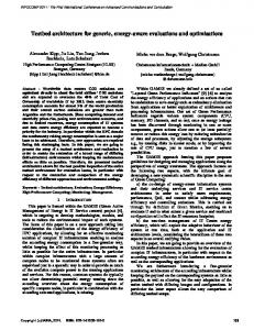
70 Considering an inter site distance among gNBs of even 500m, the vehicle is paged in an area of 1.5 km that makes the probability of success rather high. As shown in Figure 4, as long as the number of gNBs increases, the signalling reduction gain of the RAN-based mobility management scheme, compared to CN based one, is rather low. On the other hand, CEMOB outperforms these two schemes considerably since we take advantage of the accurate information about the location of the UE/vehicle CEMOB’s relative gain is improved when the number of gNBs in an area increases since the baseline mobility management schemes need to page a larger number of gNBs. To estimate the number of messages to be exchanged during a location update we perform the following analysis. As shown in Figure 2, for the RAN based scheme, 7 messages need to be exchanged every time a UE crosses the border of an RNA or when it resumes an RRC connection in a gNB that is different from the last serving gNB. A similar number of messages is needed for the CN based scheme, but this time the communication takes places between a gNB and AMF, instead of the last serving gNB. For the CEMOB case, the UE context needs to be transferred to all gNBs of an area before the UE enters into it. Also, in case a UE selects with a probability p, a different path for any reason, then it will communicate again with the V2X application server and the context will have to be updated again to all the gNBs of an area. To perform an evaluation of CEMOB for the signalling load we consider an area of 15 gNBs containing 3 RNAs. We also consider that a street has two lanes. According to [17], the vehicle traffic flow with measurement at a point is “the number of vehicles that passes a point on a highway or a given lane or direction of a highway during a specific time interval”. Traffic flow q is expressed in vehicles/hour and is given by:
𝑞=
𝑛𝑡 𝑡
distance among them, it is easy to calculate the number of vehicles in this area. Using this number, we can select a probability that some of the vehicles will change their path, so CEMOB will have to update all the gNBs of an RNA. Figure 5 presents the results for different vehicle speeds (from 20 to 60km/h) and different space headways (from 4.5 to 22.5 meters). For this experiment, we consider that every 30 sec the 20% of the vehicles will request a path update. As seen from the figure, CEMOB significantly outperforms the baseline schemes. The reason is that the ondemand context transfer requires a lot of signalling even if this is requested from one gNB to another inside an RNA. In such cases, the CN has to be notified so that path switching is performed. On the other hand, CEMOB has to notify the gNBs only once and pre-configure the RAN-CN communication path at the same time. For a small number of cells, even for the exemplary topology under consideration, this means a considerable signalling reduction. Although CEMOB needs to update the gNBs every time a UE changes its path, this cost can be minimized by selecting a subset of gNBs to be updated at a time (e.g., only the time relevant part of the endto-end path). In the case of the baseline schemes, the signalling cost is heavily affected by a complex process that may take place every time a UE is paged or whenever it switches from and idle to a connected state.
()
where nt is the number of vehicles passing a particular point in a defined period t. Related to the flow of vehicles the space headway parameter can also be used to derive q [17]. The average space headway ̅̅̅ ℎ𝑠 is defined as the distance measured between the front ends of two successive vehicles (as the sum of the vehicles’ in-between space and a vehicle’s length). Based on this parameter the traffic flow can be calculated as:
Figure 5: Signaling comparison between CEMOB and baseline scheme
Obviously, the penalty for CEMOB is the transfer of contextual information to many more gNBs (all the gNBs inside an RNA) compared to the baseline schemes where this information is transferred only from one gNB to another. To evaluate this penalty, we present the following analysis. According to [18], the security information that needs to 𝑣̅ 𝑞 = ̅ℎ𝑠 () be transferred to the gNBs and is part of the contextual ̅̅̅ information is approximately 624 bits and consists of a) KASME key (256 bits), b) K-eNB key (256 bits) and c) where the flow q is calculated as the average speed 𝑣̅ of the NONCE (32 bits). Also the Globally Unique Temporary UE vehicles divided by their average space headway. Based on Identity GUTI (80 bits). This information needs to be this, we are able to calculate the traffic flow of vehicles transferred the corresponding gNBs that are involved either passing through the 3 RNAs border areas per hour. Our in the RAN based mobility management scheme or the assumption is that for the baseline schemes (i.e., CN and CEMOB mechanism. RAN based), a UE will resume its connection once every 5 cells. Having also a fixed road topology and assuming a uniform distribution of vehicles with fixed space headway
2018, © Copyright by authors, Published under agreement with IARIA - www.iaria.org
International Journal on Advances in Telecommunications, vol 11 no 1 & 2, year 2018, http://www.iariajournals.org/telecommunications/
71
Figure 6: Additional data transfer needed for CEMOB
In Figure 6 we present the additional information needed to be transferred for CEMOB when compared to the baseline scheme in terms of MB/h for a fixed topology and different space headway among vehicles. The settings of this experiment were the same with the previous one (e.g., number of gNBs, size of an RNA, probability of changing path, etc.). As expected CEMOB always underperforms compared to the baseline scheme. The additional overhead of CEMOB for transferring contextual information is minimized when the space headway value increases since less vehicles are moving on the street and participate in mobility management functions. In all cases the additional amount of information that needs to be transferred over the wireline CN-RAN link for the case of CEMOB seems to be rather manageable for existing mobile networks. As shown in Figure 6 the worst case for CEMOB is for an average space headway of 4.5 meters for vehicles travelling at 60 Km/h. For this case only an additional 27 Mbps needs to be exchanged between the AMF and the gNBs over the wired part of the network. Overall, CEMOB minimizes the signalling load and the interactions among NFs for mobility management procedures by taking advantage of contextual information that is related to the specificities of the V2X use cases. As we will demonstrate in the next Section the same principle may be applied to other network control functions like the management of network resources in a way that minimizes the communication delay among vehicles. This minimization is of paramount importance for autonomous driving applications. V.
The average duration of the overall procedure involved in obtaining the first schedule grant is about 10msec [19] thus, failing to meet the delay requirements of various V2X use cases such as cooperative collision avoidance, cooperative lane change, emergency trajectory alignment that may require an end-to-end delay in terms 3-10msec [20]. On the other hand, the delay for a UE to be granted resources for transmission is linked with the transition from RRC IDLE state to RRC CONNECTED. Table I presents the control-plane delay budget for moving from IDLE to CONNECTED which in total is approximately 50msec. In addition, 3msec is required for resources to be granted by the scheduler. The solution using the RNA concept [14], described in Section IV, introduces a “light” connected state (i.e., RRC_INACTIVE), where the UE is able to resume a connection with the RRCConnectionResume message. This procedure requires about 30msec for entering CONNECTED state from the light connected state (since interactions with the core network are omitted) [21]. Still, this solution cannot address the abovementioned strict delays. If all vehicles are always CONNECTED even though the new transmissions will require only 3msec to transmit their data, resources are wasted for having a signalling channel ready for the usage, even when the transmissions are not planned. Considering the number of vehicles in the street this can be a significant waste of resources. In case of downlink communication, the scheduling delay is insignificant, but the delay associated with the paging needs to be taken into account if the vehicle is in IDLE mode. Furthermore, in case where a vehicle crosses the boundaries of two cells, a handover has to be executed. The execution of a typical handover process requires about 30-50msec. Again, such a delay is not acceptable based on the latest specifications of 3GPP.
RESOURCE ALLOCATION IN EXISTING SYSTEMS
In cooperative automated driving (CAD) communications, vehicles need to communicate under strict delay and reliability constraints. In the existing schemes, a UE must obtain the resources from the scheduler in order to communicate. This procedure consists of the following steps (illustrated in Figure 7): a) scheduling request b) scheduling grant c) UE processing
Figure 7: UE obtaining resources from the gNB
Summarizing, the abovementioned baseline procedures have two key drawbacks. The first being the increased delay in obtaining the schedule grant and the second being the lack of assurance in getting the transmission opportunity.
2018, © Copyright by authors, Published under agreement with IARIA - www.iaria.org
International Journal on Advances in Telecommunications, vol 11 no 1 & 2, year 2018, http://www.iariajournals.org/telecommunications/
72 Table I: CP ESTABLSHMENT DELAY [22] Step Description Duration 0 1
Approaching area of interest Average delay due to RACH scheduling period
5msec
2
RACH Preamble
1msec
3
5msec
6
Preamble detection and transmission of RA response (Time between the end RACH transmission and UE’s reception of scheduling grant and timing adjustment) UE Processing Delay (decoding of scheduling grant, timing alignment and C-RNTI assignment + L1 encoding of RRC Connection Request) TTI for transmission of RRC Connection Request HARQ Retransmission (@ 30%)
7
Processing delay in eNB (Uu –> S1-C)
4ms
8
S1-C Transfer delay
Ts1c (2 – 15msec)
9
15msec
10
MME Processing Delay (including UE context retrieval of 10ms) S1-C Transfer delay
11
Processing delay in eNB (S1-C –> Uu)
4msec
12
1.5msec
13
TTI for transmission of RRC Connection Setup (+Average alignment) HARQ Retransmission (@ 30%)
14
Processing delay in UE
3msec
15
TTI for transmission of L3 RRC Connection Complete HARQ Retransmission (@ 30%)
1msec
Total LTE IDLE to ACTIVE delay (C-plane establishment)
47.5msec + 2 * Ts1c
4
5
16
VI.
values that are required by the most demanding V2X use cases (e.g., collaborative collision avoidance).
2.5msec
1msec 0.3 *5ms
Ts1c (2 – 15msec)
0.3 *5msec
0.3 *5msec
CARP: CONTEXT-AWARE RESOURCE PREALLOCATION
One of the key characteristics of the vehicular mobility is that they have restricted spatial distribution since the vehicles have specific dimensions and their mobility is confined to the dedicated road infrastructure which is of certain capacity. Consequently, the maximum number of vehicles on a road segment is known beforehand. Additionally, by considering safety aspects, inter-vehicle distance can be taken into account to know the maximum density of the vehicle-UEs. The above observation leads to the outcome that, in certain cases, allocating resources in advance on a pergeographical area basis, rather than per-UE basis, will not be extremely costly for having collision free communication. Figure 8 illustrates such geographical area division in an intersection marked by the grid lines where each block in the grid can be allocated with resources beforehand. Also, the cost incurred by the pre-allocation can be further reduced if the resource pre-allocation is combined with spatial reuse by limiting the transmission power. Such an approach (i.e., preallocating resources in specific areas and for specific use) eliminates the delay in obtaining the resources. The gain of such an approach is that it limits the communication delay to
Figure 8: Pre-allocation Layout
The knowledge about the existence of these resources can be communicated to the vehicles in advance (during initial attachment or tracking area updates). Hence, it has the potential to meet the delay-bound requirements without the need for scheduling. By availing context information, the pre-allocation strategy can support collision free low delaybound communication with a guaranteed delay. Obviously, the penalty of this scheme is that the pre-allocated resources are wasted if there is no need to be used. On the other hand, there are not really any other alternatives to support delays in the magnitude of a few milliseconds unless all vehicles are always in a connected state. But this requires even more resources from the network. Context information about the streets and specific geography (e.g., crossings, junctions, highways, etc.) combined with information about the traffic limitations (e.g., speed limitations, etc.) facilitate proper splitting of the geographical area and allocation of the resources where these are needed (e.g., in crossroads). Thus, by using the vehicle context and road topology, tailor-cut to vehicular communications, resources can be pre-allocated to specific segments on the streets. Then, vehicles can use them as long as they are on the predefined place for predefined services that require low latency and high reliability. We call this framework of pre-allocating resources in specific road segments and communicating this information to the vehicles beforehand CARP (Context Aware Resource Pre-allocation). To achieve its purpose, it is required from 5G networks to be aware of the street geography and also about the current vehicle traffic load in the streets. This is possible to achieve in 5G networks since the introduction of NEF allows application functions such as the V2X application server to exchange information both with control functions but also to the Network Management System. By analyzing the context information for the vehicles and the streets, a centralized entity may further update the
2018, © Copyright by authors, Published under agreement with IARIA - www.iaria.org
International Journal on Advances in Telecommunications, vol 11 no 1 & 2, year 2018, http://www.iariajournals.org/telecommunications/
73 pre-allocated resources accordingly. Figure 9 presents how this process takes place and the decision is distributed to the vehicles. Initially, the V2X application provides to the Network Management System (NMS) the vehicles and street context thought the NEF. The NMS, considering the street statistics and the vehicles information concludes about the proper gNBs configuration in the form of a Radio Resource Map (RR map). The NMS, by identifying segments where certain emergencies are highly probable, can proceed in certain optimizations. Then, the NMS communicates this information to the gNBs and the AMF, so as to configure the first ones and facilitate the vehicles information through the AMF. The informing of the vehicles can take place through the tracking area update procedure or every time a path diversion takes place.
Figure 10: Madrid-grid [23]
Figure 9: Provision oa radio resource map to a UE
VII.
CARP PERFORMANCE EVALUATION
To analyze the capacity requirements of the preallocation scheme, an urban environment described by the urban information society use case in METIS I project has been used [23]. This urban topology is based on the Madridgrid as shown in Figure 10. The dimension of the grid is considered to be 387m in width and 552m in height with lanes of 3m width. The length of a vehicle is assumed to be 4m and the number of microcells is assumed to be 24. Considering 8 horizontal lanes and 10 vertical lanes, the total length of lanes without overlap is (387-30)*8 + 552*10 = 8376m. Then, when the road is congested at its maximum capacity, the maximum number of vehicles on the road can be 8376/4 = 2094. The assumptions for the evaluation are presented in Table II.
Figure 11 presents the cost of the pre-allocated resources in terms of required resource blocks for guaranteeing transmission opportunities for various vehicular densities. Here, each resource block is considered to have 12 subcarriers with inter subcarrier spacing of 15 kHz as per the existing LTE system. The considered messages are of 100 bytes size and are required to be transmitted within 5ms. It is observed from the evaluations that the cost of preallocation can be as low as only 6 resource blocks when vehicles are moving with the speed of 15m/s and using a Modulation and Coding Scheme (MCS) 15. Even under the higher density scenarios and MCS 15, the cost associated is only about 17 resource blocks to achieve the required delay. In this analysis we observe that in cases of low intervehicular distance a larger amount of resources for the preallocation (i.e., ~ 9-10 MHz) is needed. Whereas when the inter-vehicular distance is rather high the cost of preallocation of resources is quite low (~ 1-1.5 MHz).
Table II: Assumptions of the evaluations
Parameter Vehicle size Inter-vehicle distance Packet size Transmission interval Number of gNB
Value 4m 2.5sec 100 bytes 5msec 24
Figure 11: Pre-allocation Cost
However, the abovementioned case is rather extreme since we need to pre-allocate resources in the overall area
2018, © Copyright by authors, Published under agreement with IARIA - www.iaria.org
International Journal on Advances in Telecommunications, vol 11 no 1 & 2, year 2018, http://www.iariajournals.org/telecommunications/
74 under consideration. A more realistic use case relates to the pre-allocation of resources only in the areas of interest (e.g., crossings) and only for certain distance from these points of interest. To analyze the cost of pre-allocation in such points of interest, intersection areas of the map are considered. In particular, one small intersection (cross of 2 vertical and 2 horizontal lanes) and one large intersection (cross of 6 vertical and 2 horizontal lanes) including area of 50m radius from the center of these intersection are analyzed. The cost analyses of these intersections are given in Figure 12 considering each case with MCS 15 and 20. It is observed that with about 4 to 6 resource blocks, pre-allocation can support low latency communications even under higher density intersections. This translates to the bandwidth requirement of only ~0.7 MHz – 1 MHz along with additional 10% of the required bandwidth for guard bands. This cost is rather acceptable assuming the 10MHz bandwidth is typically allocated for V2V communications [24].
the future, for the next releases of 5G specifications, similar approaches will be followed for the further elaboration of the overall 5G architecture as a framework, as well as, the fine tuning of NFs that will support the operation of the different network slices on a per use case basis. IX.
CONCLUSIONS
This paper makes the case that although the specification of 5G networks is well underway and slicing is gradually reaching a mature status, several inefficiencies still exist. Standardization activities have sensibly focused on introducing new principles like NF modularization and the support of different numerologies in RAN and ported existing functionalities into the new principles. What is still missing though are further optimizations, that can be realized if use case specific context information is taken into account. In this paper, we have presented a new mobility management scheme that outperforms the baseline for the case of high moving UEs, like the autonomously driven vehicles. By taking advantage of the knowledge of the path that a vehicle will follow and by tailoring cut the involved network functions (e.g., AMF, NEF) appropriately, then significant benefits can be achieved in terms of signalling reduction with a manageable penalty of additional information being moved inside the network. Moreover, we have introduced a novel approach to preallocate resources in road segments, where this is required (e.g., crossroads) and use this information to minimize the communication delay among vehicles. This is achieved by allocating not a significant amount of resources. As a next step of the current work, we will evaluate the proposed schemes using event driven simulations.
Figure 12: Pre-allocation Cost at intersection
VIII. KEY FINDINGS As we have illustrated in the paper, the 5G architecture is flexible enough and gives a new opportunity to support very demanding use cases for the vertical industries. Having the appropriate functions in place (e.g., NEF) and by allowing the communication of the application functions (e.g., V2X application server) with the network components it is possible to collect the necessary static (e.g., streets geography) or dynamic (the moving path of a vehicle) contextual information and re-design the operation of control functions. In our view, what is missing from the current version of the specifications is exactly this consideration of contextual information and how it can improve the control functions of the networks. Information about the path and the speed of a UE, the maximum number of UEs the geography of the streets (e.g., crossroads etc.) can assist considerably in minimizing the communication delay, increase the reliability and alleviate the signaling cost in a network. This strategy of re-examining the network control operations based on the available contextual information can be adopted not only for the V2X case but also for all types of verticals (e.g., mIoT communications). We expect that in
REFERENCES [1]
[2]
[3]
[4]
[5]
[6] [7]
[8]
P. Spapis, C. Zhou, A. Kaloxylos, “On V2X Network Slicing: Using Context Information to Improve Mobility Management”, IARIA INNOV 2017, Athens, Greece, October 2017. NGMN Alliance, 5G white paper, v 1.0, 2016 available from: https://www.ngmn.org/uploads/media/NGMN_5G_White_Paper_V1 _0.pdf, access date 12-09-2017. S.E. Elayoubi, M. Fallgren, P. Spapis et al., “5G service requirements and operational use cases”, European Conference on Networks and Communications EuCNC 2016, DOI: 10.1109/EuCNC.2016.7561024. P. Marsch et al., “5G Radio Access Network Architecture: Design Guidelines and Key Considerations”, IEEE Communications Magazine, vol. 54, issue 11, pp 24-32, November 2016. X. An et al., “Architecture Modularisation for Next Generation Mobile Networks”, European Conference on Networks and Communications EuCNC 2017, DOI: 10.1109/EuCNC.2017.7980664. 3GPP, TS 23.501 “System Architecture for the 5G System; Stage 2 (Release 15)”, Version 15.0.0, December 2017. 5G-PPP Architecture Working Group, “View on 5G Architecture (Version 2.0), July 2017, available at: https://5g-ppp.eu/5g-ppprevised-architecture-paper-for-public-consultation/, access date 1209-2017. 3GPP, TS 22.261, “Service Requirements for the 5G System”, V16.2.0, January 2018.
2018, © Copyright by authors, Published under agreement with IARIA - www.iaria.org
International Journal on Advances in Telecommunications, vol 11 no 1 & 2, year 2018, http://www.iariajournals.org/telecommunications/
75 [9]
[10] [11] [12]
[13]
[14]
[15] [16]
[17]
[18] [19] [20]
[21]
[22]
[23] [24]
5G Automotive Association - 5GAA, “The case for Cellular V2X for Safety and Cooperative Driving”, available at: http://5gaa.org/pdfs/5GAA-whitepaper-23-Nov-2016.pdf, access date 12-09-2017. 3GPP, TS 23.502, “Procedures for the 5G System”, Stage 2 (Release 15), Version 15.0.0, December 2017. 3GPP, TS 38.300, “NR and NG-RAN Overall Description”, Stage 2 (Release 15), Version 15.0.0, January 2018. 3GPP TR 28.801, “Study on management and orchestration of network slicing for next generation networks”, Release 15, Version 15.1.0, January 2018. K. Chatzikokolakis, A. Kaloxylos, P. Spapis, N. Alonistioti, and C. Zhou, “A survey of location management mechanisms and an evaluation of their applicability for 5G cellular networks”, Recent advances in Communications and Networking Technologies, vol. 3, no. 2, 2014. S. Hailu and M. Säily, “Hybrid paging and location tracking scheme for inactive 5G UEs”, European Conference on Networks and Communications EuCNC 2017, DOI: 10.1109/EuCNC.2017.7980730. 3GPP TS 23.285, “Architecture enhancements for V2X services”, Release 14, Version 14.5.0, December 2017. R. Trivisonno, R. Guerzoni, I. Vaishnavi, and D. Soldani, “Towards zero latency software defined 5G networks,” in IEEE International Conference on Communication Workshop (ICCW), June 2015, pp. 2566–2571. T. V. Mathew and K. V. Krishna Rao, “Introduction to Tranportation Engineering”, Chapter 30, Fundemental parameters of traffic flow, May 2007, available at: http://nptel.ac.in/courses/105101087/downloads/Lec-30.pdf, access date 15-05-2018. 3GPP, TS 33.401, “Security Architecture”, Release 15, Version 15.2.0 January 2018. 3GPP, TR 36.912, "Feasibility study for Further Advancements for EUTRA (LTE-Advanced)", Version 14.0.0, March 2017. N.G.M.N. Alliance, "Perspectives on vertical industries and implications for 5G", 2016, available at: https://www.ngmn.org/publications/alldownloads/?tx_news_pi1%5Bnews%5D=516&cHash=191d94c830ec 204060fdc44deb5aef32, access date 16-05-2018. I. L. Da Silva, G. Mildh, M. Säily, and S. Hailu, "A novel state model for 5G Radio Access Networks," 2016 IEEE International Conference on Communications Workshops (ICC), Kuala Lumpur, 2016, pp. 632-637. 3GPP, TR 25.912, "Feasibility study for evolved Universal Terrestrial Radio Access (UTRA) and Universal Terrestrial Radio Access Network (UTRAN)”, Version 14.0.0, March 2017. METIS, "Simulation guidelines", Deliverable D6.1, October 2013. 3GPP, TR 36.885, "Study on LTE-based V2X Services", Version 14.0.0, June 2016.
2018, © Copyright by authors, Published under agreement with IARIA - www.iaria.org