Dec 14, 1987 - The implementation of conventional linear control tech- niques have led to .... The controller decouples the linearized system, thus allowing a design pro- ... terrelationships between the robot arm structural flexibility and the ...... D'Azzo, J., and Houpis, C. H., 1981, Linear Control System Analysis and. Design ...
N. G. Chalhoub Assistant Professor, Department of Mechanical Engineering, University of Nevada-Reno, Reno, Nevada 89557-0030 Assoc. Mem. ASME
A. G. Ulsoy Associate Professor, Department of Mechanical Engineering and Applied Mechanics, University of Michigan, Ann Arbor, Mich. 48109-2125 Mem. ASME
1
Control of a Flexible Robot Arm: Experimental and Theoretical Results The operation of high precision robots is severely limited by. their manipulator dynamic deflection, which persists for a period of time after a move is completed. These unwanted vibrations deteriorate the end effector positional accuracy and reduce significantly the robot arm production rate. A "rigid and flexible motion controller" is derived to introduce additional damping into the flexible motion. This is done by using additional sensors to measure the compliant link vibrations and feed them back to the controller. The existing actuators at the robot joints are used (i.e., no additional actuators are introduced). The performance of the controller is tested on a dynamic model, developed in previous work, for a spherical coordinate robot arm whose last link only is considered to be flexible. The simulation results show a significant reduction in the vibratory motion. The important issue of control and observation spillover is examined and found to present no significant practical problems. Partial evaluation of this approach is performed experimentally by testing two controllers, a "rigid body controller" and a "rigid and flexible motion controller, " on a single joint of a spherical coordinate, laboratory robot arm. The experimental results show a significant reduction in the end effector dynamic deflection; thus partially validating the results of the digital simulation studies.
Introduction
The operation of high precision robots is severely limited by their manipulator dynamic deflection, which persists for a period of time after a move is completed. The settling time required for this residual vibration delays subsequent operations, thus conflicting with the demand for increased productivity. These conflicting requirements between high speed and high accuracy have rendered the robotic assembly task a challenging research problem. The automation of assembly tasks will be greatly enhanced if robots can operate at higher speeds with greater positioning accuracy. These goals cannot be achieved with the existing massive robot designs, which make them slow and heavy. Many robot arms are made to be massive for increased rigidity. For higher operating speeds, mechanisms should be made lightweight to reduce the driving torque requirements and to enable the robot arm to respond faster. Lightweight robot structures are also desirable for space applications. However, lighter members are more likely to elastically deform, thus making it a necessity to take into consideration the dynamic effects of the distributed link flexibility. This is because high speed operation leads to high inertial forces which in turn cause vibration and deteriorate accuracy. To obtain an accurate dynamic model for a very flexible structure, all the coupling terms between the flexible and the Contributed by the Dynamic Systems and Control Division and presented at the Winter Annual Meeting, Boston, Mass., December 14-17, 1987 of THE AMERICAN SOCIETY OF MECHANICAL ENGINEERS. Manuscript received at ASME
Headquarters May 21, 1987. Paper No. 87-WA/DSC-3.
rigid body motions need to be retained. This is done by using coupled reference position and elastic deformation models. The resulting equations, which represent the combined rigid and flexible motions, are coupled and very complex. They reveal the nonlinear and nonstationary characteristics inherent in robotic manipulators. The implementation of conventional linear control techniques have led to poor performance because of both the inherent geometric nonlinearities of these systems, and the dependence of the system dynamics on the characteristic of the manipulated objects. Therefore, a sophisticated controller design is needed to ensure the desired performance of the robot. In the control of rigid robots, adaptive, nonlinear, and optimal control techniques have been investigated. Adaptive control theory (Dubowsky and Desforges, 1979, Horowitz and Tomizuka, 1980, Landau, 1979, Balestrino et al., 1983, Lee and Lee, 1984, Donalson and Leondes, 1963) has been proposed as a promising solution to the nonlinearity and nonstationarity problems. The main task is to adjust the feedback gains of the arm controller so that its closed loop performance characteristics closely match the desired ones. However, the large required computation time has restricted the application of adaptive control strategies to simulation studies. Nonlinear control, or the "computed torque" method (Gilbert and Ha, 1984), has led to better performance over conventional control techniques in computer simulations. The controller is based on an idealized model of the manipulator. This is a severe drawback because when the "idealized" con-
Journal of Dynamic Systems, Measurement, and Control
DECEMBER 1987, Vol. 109 / 299
Copyright © 1987 by ASME Downloaded From: http://dynamicsystems.asmedigitalcollection.asme.org/ on 11/17/2014 Terms of Use: http://asme.org/terms
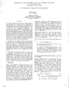
motor drive for second beam
P»ylo«d.^
leadacrew
feedscrew
motor drive (or the first beam
Jil cross section of the first beam Fig. 1
©-7 cross section of the second beam
A schematic of the physical system
trol law is applied on an actual plant, the validity of the scheme will be subject to doubt and the robustness of the controller becomes of great importance. A time optimal control strategy is studied by Sangveraphunsiri and Book (1982) to enable faster movement of the robot arm. Kahn and Roth (1971) showed that this technique results in a two point boundary value problem. As a consequence, the computation must be repeated for each new set of initial and final conditions used in the numerical solution. In addition, the numerical algorithm yields an optimal solution that is a function of time and does not account for any unexpected disturbances which may act on the system. These drawbacks have rendered the implementation of the time-optimal control technique difficult, if not impossible, for real time application in feedback control of robots. However, this technique has turned out to be a powerful tool for off-line trajectory planning. In an attempt to relax these difficulties, a suboptimal control strategy is often used in digital simulations. In this technique, a linearized version of the dynamic model of the manipulator is obtained for which an analytical optimal control solution can be found.
Many of these sophisticated control techniques suffer from excessive computation time requirements which make them unattractive for real time applications using current microprocessor technology (Wang and Sharma, 1984). Besides the difficult issues encountered in rigid robots, a new problem is created when robot compliance is included in the dynamic model. It emanates from the distributed nature of the link mass and elasticity. An infinite number of degrees of freedom are required to specify the position of every point on the elastic link. However, due to physical limitations, only a finite number of sensors and actuators can be mounted on the flexible body. Thus resulting in the problem of controlling a large dimensional system with a smaller dimensional controller (Balas, 1978) and (Takahashi et al., 1972). Two types of forcing functions, to achieve fast response with negligible residual vibrations, are proposed by (Meckl and Seering, 1983) and (Meckl and Seering, 1985). The first type allows vibration to occur during the move but would stop the motion in such a way as to eliminate any residual vibration. The second type avoids the excitation of the resonant modes of the structure as it moves. This work is still at a research level; it can be used off-line to generate the trajectory of the robot arm that satisfies a criterion considering both the time response and the residual vibration. By and large, the research in the closed loop control of flexible manipulators can be divided into two categories. The first uses additional sensors to measure the flexible motion. That is, all state variables are assumed to be available (Usoro, et al., 1984, Fukuda and Kuribayashi, 1984, Cannon and Schmitz, 1983, Book and Majett, 1982). This enables the inclusion of the flexible motion in the control action, thus achieving better positional accuracy with the existing joint motors. The second category employs a micromanipulator along with additional sensors to compensate for both static and dynamic structural deflections (Zalucky and Hardt, 1982, Cannon et al., 1983, Singh and Schy, 1985). This concept gives the control system designer more capabilities to improve the robot arm performance at additional hardware cost. Throughout this paper, the term "rigid body controller" is used to refer to the controller whose main objective is to control the rigid body motion of the robot arm, whereas the term "rigid and flexible motion controller" refers to the controller that compensates for both the rigid and flexible motions.
Nomenclature
dinate vector, (i, j , k) = noninertial, body fixed, rotating reference frame mp = mass of the payload qu(t) = flexible motion generalized coordinate in the vertical direction for mode / (i = 1, 2) #2/(0 = flexible motion generalized coordinate in the horizontal direction for mode i (/ = 1, 2) r, 6, = rigid body degrees of freedom of the robot arm u = control vector x = generalized coor300/Vol. 109, DECEMBER 1987
XT
V(y,t) = £ 9 u (0**00
= [r,Q, ,