(c) 2002 IEEE. Personal use of this material is permitted. Permission from IEEE must be obtained for all other users, including reprinting/ republishing this material for advertising or promotional purposes, creating new collective works for resale or redistribution to servers or lists, or reuse of any copyrighted components of this work in other works.
Control of Power Quality in Inverter-Based Distributed Generation
Author 1: Milan Prodanovi´c Affiliation: Department of Electrical and Electronic Engineering, Imperial College, UK Contact Address: Milan Prodanovi´c Post-Graduate, Electrical Engineering, Imperial College Exhibition Road, London SW7 2BT, UK Phone: +44 (0)20 7594 6295 Fax: +44 (0)20 7594 6282 e-mail:
[email protected] Author 2: Timothy Charles Green Affiliation: Department of Electrical and Electronic Engineering, Imperial College, UK Contact Address: Dr Tim Green Electrical Engineering, Imperial College Exhibition Road, London SW7 2BT, UK Phone: +44 (0)20 7594 6171 Fax: +44 (0)20 7594 6282 e-mail:
[email protected]
Corresponding Author: Milan Prodanovi´c Topical Area: power electronics Subject Area: power converters, digital control of power electronics Index terms: power quality, three-phase inverter, grid-connection, inverter control
(c) 2002 IEEE. Personal use of this material is permitted. Permission from IEEE must be obtained for all other users, including reprinting/ republishing this material for advertising or promotional purposes, creating new collective works for resale or redistribution to servers or lists, or reuse of any copyrighted components of this work in other works.
Control of Power Quality in Inverter-Based Distributed Generation
Authors: Milan Prodanovi´c, Timothy C. Green Affiliation: Department of Electrical and Electronic Engineering, Imperial College, UK
Abstract - Power quality is an important additional service of inverter-based interfaces for distributed generators. In grid connected applications the power quality depends on the harmonic content of the current injected at the point of common coupling. By careful design of the power converter and its output filter the switching frequency components in the output current spectrum can be reduced to low levels. The effect of the harmonic distortion of the grid voltage on the output current can be minimised by using an appropriate inverter control strategy. Conventional control methods (manipulation of inverter voltage magnitude and phase) offer active and reactive power control, but not the control of the output current quality. This paper describes a new choice of control structure and explains the interaction between the applied control loops. The inverter is used to control the current in the first element of an LCL filter. A further controller is wrapped around this loop to control power export to the grid. The usefulness of this arrangement in providing high power quality is emphasised. Experimental results from a 10kVA prototype are used to evaluate the distortion rejection properties and the regulation of active and reactive power control. The results show high quality of generated power and excellent transient and steady state-response to both active and reactive power demands.
(c) 2002 IEEE. Personal use of this material is permitted. Permission from IEEE must be obtained for all other users, including reprinting/ republishing this material for advertising or promotional purposes, creating new collective works for resale or redistribution to servers or lists, or reuse of any copyrighted components of this work in other works.
Control of Power Quality in Inverter-Based Distributed Generation Milan Prodanovi´c and Timothy C. Green Department of EEE, Imperial College Exhibition Road, London SW7 2BT, UK
[email protected],
[email protected] Abstract— Power quality is an important additional service of inverter-based interfaces for distributed generators. In grid connected applications the power quality depends on the harmonic content of the current injected at the point of common coupling. By careful design of the power converter and its output filter the switching frequency components in the output current spectrum can be reduced to low levels. The effect of the harmonic distortion of the grid voltage on the output current can be minimised by using an appropriate inverter control strategy. Conventional control methods (manipulation of inverter voltage magnitude and phase) offer active and reactive power control, but not the control of the output current quality. This paper describes a new choice of control structure and explains the interaction between the applied control loops. The inverter is used to control the current in the first element of an LCL filter. A further controller is wrapped around this loop to control power export to the grid. The usefulness of this arrangement in providing high power quality is emphasised. Experimental results from a 10kVA prototype are used to evaluate the distortion rejection properties and the regulation of active and reactive power control. The results show high quality of generated power and excellent transient and steady state-response to both active and reactive power demands.
I. Introduction In recent years, the number of different power resources connected to the power system (voltage grid) has increased and there has been a move toward connecting small power resources to the medium and low voltage networks rather than large resources to the high voltage network. Power sources such as wind turbines, combined heat and power (CHP) and solar energy are already well established and fuel-cells and microturbines are being demonstrated. Many of these resources use synchronous generators for interconnection to the grid. However, there is an increased number of sources that are natural DC sources or whose AC frequency is not constant or is much higher than the grid frequency. In some of these cases three-phase inverters have been used. So far, only smallscale power applications have used inverters because of limited component availability, heat dissipation problems, reliability concerns and cost. The availability of high power semiconductor switches has increased and there may now be more inverter applications in small-scale power generation (up to 1MVA). The trend toward modular construction of power electronic systems increases power capacity, but also improves system reliability and efficiency (on part load) [1]. Power quality requirements for connection of an inverter to the grid are defined by [2]. For mini-grids these requirements are still under development [3], since previously there have not been many similar high power applications. In [4] it is stated that the power quality is determined by the voltage quality, when the voltage is a controlled variable. If there is connection to an existing (stiff) grid, then the voltage cannot be controlled. The power quality is then defined by the current quality. Further, it is specified [3] that the inverter must
not oppose or regulate the voltage at the point of common coupling (PCC). In most existing applications when an inverter is connected to the grid [5], the output voltage is controlled in a similar way to control of a synchronous machine. In such an arrangement, the output current quality depends on the grid voltage quality. If the inverter operates as a current source, the current quality is independent of the voltage quality and can be maintained high. The drawback of this arrangement is the high frequency content injection into the power system generated by inverter switching, since a single inductor is the only filter component used. In order to further suppress switching frequency components from the output current a filter capacitor must be inserted. Under this condition a new control scheme must be sought. While conventional control methods (inverter voltage and magnitude change) offer active and reactive power control they cannot control the quality of the output current. This paper proposes a control solution that combines phase-lock loop, current control and power control startegies to provide active and reactive power control while maintaining high quality output current and power. Theoretical analysis and experimental results are provided to show validity of the proposed method.
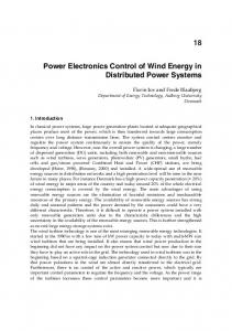
II. System Description and Control Strategy Figure 1 shows a typical inverter connection to the grid (at the PCC) via an isolating transformer that provides protection and eliminates zero sequence components from the inverter output voltage. The inverter filter components and the switching frequency are determined by specifying the power quality, efficiency and component size (cost). The switching frequency in most power applications is kept below 10kHz because of the inverter efficiency and limitation of available semiconductors. The role of the LC filter is to provide filtering of switching frequency spectral components. The inductor current ripple determines the value of inductor, while the capacitor value is chosen to represent a small impedance at the switching frequency (compared to the series impedance of the grid connection). In many applications of grid-connected inverters [5] [6] the inverter is operated as a voltage source where the inverter voltage vI is controlled and an inductor alone is the interface to the grid. By mimicking operation of a synchronous generator (changing the voltage magnitude and phase) the output active and reactive power have been successfully controlled. Because in this mode the inverter generates an ideal sinusoidal pulsewidth modulated voltage at its output, the output current and power quality depend on the grid voltage quality. If the grid
Fig. 1. Inverter connected to the voltage grid
(c) 2002 IEEE. Personal use of this material is permitted. Permission from IEEE must be obtained for all other users, including reprinting/ republishing this material for advertising or promotional purposes, creating new collective works for resale or redistribution to servers or lists, or reuse of any copyrighted components of this work in other works.
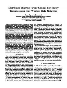
Fig. 2. Control model for grid-connected mode of operation
voltage is distorted or if there is voltage unbalance in the grid, the exported output current is distorted or unbalanced. This relation degrades the output power quality, since the generating system adds to the distortion of the grid by presenting low impedance to existing distortion voltage. The main advantage of using a current source inverter instead of a voltage source is that within the control frequency range the output impedance (observed from the inverter output terminals) is higher. This minimises effect of grid voltage harmonics at the PCC on the output current and improves the power quality. Not only must the inductor current quality be controlled within the low frequency range (below the 40th harmonic), but also higher frequency ripple components due to inverter switching operation must not be injected into the grid. Therefore, an output filter capacitor is used and its reactance is chosen to be smaller than the series impedance to the grid connection at the switching frequency. The capacitor current contributes to the output current and its quality depends on the voltage quality. It is essential to choose the minimum value of capacitance that satisfies the switching frequency attenuation so that inverter reactive power storage is minimised and a high impedance is presented to grid voltage distortion. The control strategy is to generate high quality balanced three-phase currents and to control power at the output of the inverter. If this is achieved, the inverter does not represent a harmonic source connected to the grid but a high quality power generator. The voltage vG at the PCC is not always available to sense and the assumption is that only the local inverter variables are sensed: inductor currents iL , capacitor voltages vO and output currents iO . A three-phase inverter control topology for grid connection is shown in Figure 2. It consists of three control loops: internal inductor current control loop, external power control loop and phase-locked loop. The control is performed in rotational reference frame because of the advantages for instantaneous active and reactive power calculation [7] and simpler fundamental frequency current control. All sensed variables are transformed into a rotational reference frame using phase angle θ∗ which is locked to the output voltage reference phase angle using a phase-locked loop. The power controller calculates active and reactive power at the
output and sets the inductor current references i∗LDQ . Current controllers set the normalised output voltage references ∗ vnormIDQ of the inverter in order to control inductor currents. In order to provide high performance current control, the bandwidth of the current controllers is set as high as possible with the given limitations of the hardware. This is an essential condition to improve output power quality under distorted three-phase grid voltages.
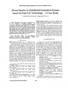
III. Phase-Locked Loop There are two basic approaches to the realisation of a phaselocked loop (PLL) for a three-phase voltage system. One [8] uses a method of error minimisation between the input square wave signal from the voltage zero crossing comparators and the signal from the local oscillator. The other method is presented in several papers [9] [10] [11] and it uses rotational reference frame to obtain the D and Q components of three-phase voltages. In this method, when one of those components is constant then the frequency of the DQ-system is set to the frequency of grid voltage. It is convenient to set one of the components to zero, since then the applied regulator has to maintain that value at zero by changing the frequency of rotation of the DQ-system. In the case when the three-phase voltage is distorted or unbalanced, this approach is more suitable for application because it locks to the frequency of fundamental. The PLL structure is shown in Figure 3 and it consists of a PI controller (which minimises the error signal, that is, the Q-axis voltage component) and an integrator (to calculate the phase from the frequency). The controller itself provides sufficient harmonic suppression, because the changes of frequency are rarely faster than 1Hz/s which determines the bandwidth of PLL.
Fig. 3. PLL structure
(c) 2002 IEEE. Personal use of this material is permitted. Permission from IEEE must be obtained for all other users, including reprinting/ republishing this material for advertising or promotional purposes, creating new collective works for resale or redistribution to servers or lists, or reuse of any copyrighted components of this work in other works.
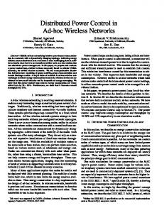
Fig. 5. Power Controller Fig. 4. Current Controllers
IV. Current Control Loop An inductor current control loop is essential in grid connection of inverters. It provides three-phase balanced current injection to the grid. An advantage of using current control is that non-linearity of the inverter switching and external disturbances are dealt with within that loop. There are two sources of disturbance to the current controller: changes in the DC-link voltage VDC and disturbance of the grid voltage. It is assumed that within the control frequency range the transformer impedance is smaller than the impedance of the filter capacitor. The current control is performed in the rotational reference frame. System equations are shown in 1, where ω is the grid angular frequency, L the inductance and vI the inverter voltage.The filter output voltage vO represents a disturbance for the current control loop.
· · +
1 L
0 1 L
0
˙ iLD ˙ iLQ
¸·
¸
· =
vID vIQ
¸
0 −ω
·
−
ω 0 1 L
¸·
0
iLD iLQ
¸·
1 L
0
¸ +
vOD vOQ
¸ (1)
The control structure is shown in Figure 4. A PI controller is used to obtain zero steady state error and compensate for inverter switching non-linearities and inductor nonidealities. To minimise the disturbance from the grid voltage, the feed-forward technique is used. Decoupling terms are also introduced. The low frequency disturbance coming from the changes in the DC-bus voltage is compensated by normalising controller output vectors. In order to implement the control alorithm it is necessary to examine the discrete model of the control system. When the system is discretised [12] further coupling terms apear between axes, but the control strategy remains the same. The system equations are now shown in (2) and (3) for a sampling period of T and a switching period equal to the sample period.
· · +
c −d
iLD (k + 1) iLQ (k + 1) d c
¸·
¸
vID (k) vIQ (k)
· =
¸
a = cos(ωT ) c = b/(ωL)
a −b
· −
c −d
b a
¸·
d c
iLD (k) iLQ (k)
¸·
¸
vOD (k) vOQ (k)
b = sin(ωT ) d = (1 − a)/(ωL)
techniques [13] to overcome this problem by inserting an estimator and an observer to minimise the effect of the delay time.
V. Power Control According to [7], power components can be defined as in (4) where p and q are instantaneous active and reactive power, vOD , vOQ , iOD , iOQ are instantaneous output voltages and currents in the rotational reference frame.
·
¸ (2) (3)
Because of the digital control implementation, the computational time delay must be taken into account. There are
¸
· =
vOD −vOQ
vOQ vOD
¸·
iOD iOQ
¸ (4)
There are two methods to control power: instantaneous and average power control. In the instantaneous power control method the fundamental current component and higher frequency components are controlled such that the power is constant even if the grid voltage is disturbed. The output current quality in this method depends on the grid voltage quality and, therefore, the method is not suitable for this application. The average power control method provides high quality sinusoidal output current and controls the average power flow. The role of the power controller is to generate output current references by filtering out higher harmonic content from the power spectrum. Since the power control transient response time is in the range of 100ms, the filtering provides slow changing current reference to ensure high quality inductor current. The average value of Q-component voltage vOQ is set to zero by phase-locked loop, which simplifies equation (4). However, since the bandwidth of power control is higher than the bandwidth of the PLL, the instantaneous active and reactive power must be calculated according to (4). If the current control is established and the D and Q components of current are kept constant, then the output power variation depends only on the variation of output voltages. When the power references p∗ and q ∗ and output voltages are known, a power calculator can be used (instead of a power controller) to calculate output current references iOD and iOQ . The references are calculated according to (5).
· +
p q
i∗OD i∗OD
¸
· =
vOD −vOQ
vOQ vOD
¸−1 ·
p∗ q∗
¸ (5)
In order to calculate inductor current references i∗LD and i∗LQ , the capacitor currents and decoupling terms must be added to the output current references. Therefore, the difference between the inductor currents iLD (iLQ ) and output currents iOD (iOQ ) is added to the output current reference i∗OD (i∗OQ ). The power controller structure is shown in Figure 5. To limit the power controller bandwidth and to filter
(c) 2002 IEEE. Personal use of this material is permitted. Permission from IEEE must be obtained for all other users, including reprinting/ republishing this material for advertising or promotional purposes, creating new collective works for resale or redistribution to servers or lists, or reuse of any copyrighted components of this work in other works.
ch1: 1000V/div ch2: 50A/div ch3: 50A/div
40
423VRMS
30
vG 1
20
10
25.3ARMS
0
iO [dB]
iL
−10
2
−20
−30
25.1ARMS iO
−40
3 −50
−60 0
2000
4000
6000
Fig. 6. vG , iL and iO under nominal power demand
10000
12000
Fig. 7. Output current iO spectrum showing switching frequency components
60
40
50
30
THD=2.8%
THD=2.8% 40
20
30
10
20
0
iO [dB]
vG [dB]
8000
frequency [Hz]
5ms/div
10
−10
0
−20
−10
−30
−20
−40
−30
−50
−40
−60 0
500
1000
1500
2000
2500
3000
frequency [Hz]
Fig. 8. Line voltage vG spectrum in controlled frequency range
out harmonic content from the voltage and current spectrum a low-pass filter is applied. The filter cut-off frequency fC must be set low to provide sufficient suppression of voltage harmonics and unbalance, but high enough to provide good transient response of the power loop.
VI. Experimental Results The experimental rig was built with an inverter of 10kVA and connected to the 50Hz voltage grid via an ∆ − Y 10kVA isolating transformer (the ∆ side is connected to the grid) of a primary to secondary voltage ratio of 415/208Vrms line-toline. The inverter parameters are: fS =8.192kHz, current loop bandwidth 1.9kHz, C=50µF, L=1.35mH. The isolating transformer parameters are: RS =20mΩ, LS =100µH, RM =1kΩ, LM =100mH. Full digital current control was applied and a DSP TMS320LF2407 was used to implement control algorithms and generate PWM signals to drive the inverter. The measured grid voltage vG , inductor current iL and output current iO are shown in Figure 6 under nominal active power. The grid voltage shows a phase-shift of 30◦ (and had higher RMS value), because it represents line-to-line voltage whereas vO was measured as a phase voltage. The grid voltage is seen to be a source of harmonic disturbance in the output current. In Figure 7 the output current iO is shown accross a wide
0
500
1000
1500
2000
2500
3000
frequency [Hz]
Fig. 9. Output current iO spectrum in controlled frequency range
frequency range to show the switching frequency components attenuated to 60dB below the fundamental component. This was achieved by choosing appropriate values during the inverter filter design. In Figure 8 and 9 vG and iO are shown accross the controlled frequency range. The results show the presence of 5th , 7th , 11th and 13th harmonic in the voltage spectrum. High quality output power (current) was obtained and the THD was 2.8%. The distribution of harmonics in the output current spectrum shows attenuation of 5th and 7th harmonic and the filter capacitor current contribution. Figure 9 shows also the effect of high bandwidth of current control with some amplification of noise occuring around the cut-off frequency of the current controller. The power control loop behaviour is shown in Figure 10. The instantaneous active and reactive power references and controller responses are shown in this diagram. The active power reference change was from 20% to 80%, while that for reactive was from 0% to 40% (capacitive) of nominal inverter power. It can be seen that the inverter output power follows its reference and that average power control has been established. The transient response time is less then 100ms. The inverter output impedance ZO was measured by setting active and reactive power references to zero. The result is shown in Figure 11 and is compared to the output capacitor impedance ZC . In the case of an ideal current source the
(c) 2002 IEEE. Personal use of this material is permitted. Permission from IEEE must be obtained for all other users, including reprinting/ republishing this material for advertising or promotional purposes, creating new collective works for resale or redistribution to servers or lists, or reuse of any copyrighted components of this work in other works.
1
1kVA/
2
1kVA/
3
1kVA/
4
1kVA/
80
70
p*
60
p Impedance [dB]
50
Z O
40
30
1 2 3 4
Z C
q
20
q*
10
0 0 100ms/div
Fig. 10. Power Control
output impedance is equivalent to the capacitor impedance. Since the power controller controls the fundamental frequency component, the impedance at that frequency is high. At other frequencies, the output impedance follows the capacitor impedance, but it is smaller due to finite output impedance of the inverter operated under current control.
VII. Conclusion In order to provide an appropriate control strategy for grid connection of a three-phase inverter, the power quality requirements have been discussed together with inverter properties and limitations. The importance of the inverter filter capacitance choice has been emphasised as a trade-off between attenuation of switching frequency components and attenuation of grid voltage distortion, with both affecting the output power quality. To provide a suitable control strategy for high-quality power generation with the filter capacitance in place, existing inverter control techniques have been combined and a control method has been proposed. The phase-locked loop, current control loop and power control loop have been presented and their interaction explained regarding the power quality issue. Experimental results have shown that using inductor current control instead of conventional magnitude and phase control ensures high quality of output power even under distorted or unbalanced three-phase voltage conditions in the utility grid. Active and reactive power control has been established while output current quality is maintained high. Also, it has been shown that the output impedance in the controlled frequency range is high, which minimises the effect of grid voltage distortion on the generated currents.
VIII. References [1]
[2]
[3]
J.-F. Chen, C.-L. Chu, and Y.-C. Liou, “Modular Parallel Three-Phase Inverter system,” IEEE Catalog Number: 95TH8081, pp. 237–242, 1995. IEEE Industry Applications Society/Power Engineering Society, IEEE Recomended Practises and Requirements for Harmonic Control in Electrical Power Systems. IEEE, 1992. IEEE SCC21, IEEE P1547 Std Draft 06 Standard for Distributed Resources Interconnected with Electric Power
100
200
300
400
500
600
700
800
900
1000
Frequency [Hz]
Fig. 11. Output impedance ZO and capacitor impedance ZC
[4] [5]
[6]
[7]
[8]
[9]
[10]
[11]
[12]
[13]
Systems. IEEE, 2000. M. H. Bollen, Understanding Power Quality Problems. IEEE Press, 2000. M. Chardokar, D. Divan, and R. Adapa, “Control of Parallel Connected Inverters in Stand-Alone AC Supply Systems,” IEEE Tran. on Industry Applications, vol. 29, no. 1, pp. 136–143, 1993. M. Yamaguchi, K. Kawarabayashi, and T. Takuma, “Development of a new utility-connected photovoltaic inverter LINE BACK ,” 16th International Telecommunications Energy Conference INTELEC ’94., pp. 676–682, Sep 1994. H. Akagi, Y. Kanazawa, and A. Nabae, “Intantaneuos Reactive Power Compensators Comprising Switching Devices without Energy Storage Components,” IEEE Tran. on Industry Applications, vol. IA - 20, pp. 625–630, May/Jun 1984. P.Verdelho and G.D.Marques, “Four Wire Active Power Filter Control Circuit with Phase Locked Loop Phase Angle Determination,” Power Electronics and Variable Speed Drives, 1998. Seventh International Conference on (Conf. Publ. No. 456), pp. 34–39, 1998. N.Bruyant and M. Machmoum, “Simplified DigitalAnalogical Control for Shunt Active Power Filters Under Unbalanced Conditions,” Power Electronics and Variable Speed Drives, 1998. Seventh International Conference on (Conf. Publ. No. 456), pp. 11–16, Sep 1998. V.Kaura and V.Blasko, “Operation of a Phase Locked Loop System Under Distorted Utility Conditions,” Applied Power Electronics Conference and Exposition, 1996. APEC ’96. Conference Proceedings 1996., Eleventh Annual, vol. 2, pp. 703–708, 1996. S.-K.Chung, “Phase-Locked Loop for Grid-Connected Three-Phase Power Conversion Systems,” IEEE Proc. on Elec. Power Appl., vol. 147, pp. 213–219, May 2000. T. Kawabata, T. Miyashita, and Y. Yamamoto, “Dead Beat Control of Three Phase PWM Inverter,” IEEE Transactions on Power Electronics, vol. 5, pp. 21–28, Jan 1990. Y. Ito and S. Kawauchi, “Microprocesor-Based Robust Digital Control for UPS with Three-Phase PWM Inverter,” IEEE Transactions on Power Electronics, vol. 10, pp. 196–204, March 1995.