energies Article
Control Strategies with Dynamic Threshold Adjustment for Supercapacitor Energy Storage System Considering the Train and Substation Characteristics in Urban Rail Transit Fei Lin *, Xuyang Li, Yajie Zhao and Zhongping Yang School of Electrical Engineering, Beijing Jiaotong University, No.3 Shangyuancun, Beijing 100044, China;
[email protected] (X.L.);
[email protected] (Y.Z.);
[email protected] (Z.Y.) * Correspondence:
[email protected]; Tel.: +86-10-51687064 Academic Editor: William Holderbaum Received: 30 January 2016; Accepted: 22 March 2016; Published: 31 March 2016
Abstract: Recuperation of braking energy offers great potential for reducing energy consumption in urban rail transit systems. The present paper develops a new control strategy with variable threshold for wayside energy storage systems (ESSs), which uses the supercapacitor as the energy storage device. First, the paper analyzes the braking curve of the train and the V-I characteristics of the substation. Then, the current-voltage dual-loop control method is used for ESSs. Next, in order to achieve the best energy-saving effect, the paper discusses the selection principle of the charge and discharge threshold. This paper proposes a control strategy for wayside supercapacitors integrated with dynamic threshold adjustment control on the basis of avoiding the onboard braking chopper’s operation. The proposed control strategy is very useful for obtaining good performance, while not wasting any energy in the braking resistor. Therefore, the control strategy has been verified through simulations, and experimental tests, have been implemented on the Batong Line of Beijing subway using the 200 kW wayside supercapacitor energy storage prototype. The experimental results show that the proposed control is capable of saving energy and considerably reducing energy consumption in the braking resistor during train braking. Keywords: energy storage system (ESS); supercapacitor; control strategy; train braking characteristics; traction substation; charge and discharge threshold
1. Introduction With the continuous economic development in China in recent years, urban rail transit has also undergone rapid development. From 2003 to 2013, the operating mileage of China urban rail transit increased from 290.4 km to 2326.0 km, the highest in the world [1]. In the urban rail transit system, braking energy of the train is commonly fed back to the catenary through regenerative braking. However, due to the 24-pulse diode rectifier unit used in the traction substation, surplus regenerating energy cannot provide feedback to the medium-voltage power grid. When a train is braking, if there are no adjacent traction trains or energy storage devices that can absorb the regenerative energy, then the pantograph voltage would exceed the normal range, thus leading to the onboard braking chopper operating, i.e., the braking energy is wasted by the resistor [2,3]. Even worse, regeneration cancellation may occur. Therefore, in order to maximize the use of electric braking energy, while reducing mechanical braking and resistor braking of urban rail trains, currently two main options are energy storage and energy feedback [4]. At present, the main storage devices available are batteries, supercapacitors and flywheels.
Energies 2016, 9, 257; doi:10.3390/en9040257
www.mdpi.com/journal/energies
Energies 2016, 9, 257
2 of 18
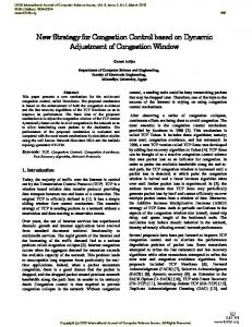
Flywheels present relatively high overall efficiencies and elevated energy and power densities. However, they have a potential risk of explosive shattering in case of catastrophic failure and they 9, 257 2 of 18 haveEnergies higher2016, mechanical structure requirements [5–7]. The Flywheels batteries present high energy density with discharge times ranging from tens of minutes to present relatively high overall efficiencies and elevated energy and power densities. hours, which can provide power forrisk theofvehicle running to the if the power supply is cut off However, they have a potential explosive shattering in safe case place of catastrophic failure and they because trouble. Besides, the batteries can be[5–7]. used in the urban rail transit to absorb the braking haveofhigher mechanical structure requirements energy and the voltage of the DC bus. Their lifefrom is shorter the to power Thereduce batteries present highfluctuation energy density with discharge timescycle ranging tens of and minutes hours, which can provide power for the vehicle running to the safe place if the power supply is cut density is relatively low. off because of trouble. Besides, the batteries be usedThey in the are urban rail transit absorb thepower brakingpeaks The supercapacitors have higher powercan density. suitable for to supplying energy andthe reduce the voltage of the DCthey bus. have Their longer cycle life is shorter power and absorbing braking power fluctuation peaks. In addition, cycle life. Inand thisthe paper, a cycle density is relatively low. is defined as the supercapacitor is charged to the maximum and discharged to the minimum value, The supercapacitors have higher power density. They are suitable for supplying power peaks which is considered one cycle. However, there are many definitions for cycle life, and it is related to the and absorbing the braking power peaks. In addition, they have longer cycle life. In this paper, a cycle control strategy [8,9]. Another added value is that, unlike batteries, which require complex algorithms is defined as the supercapacitor is charged to the maximum and discharged to the minimum value, to estimate state of charge (SOC), the determination of supercapacitor is easily obtained which isthe considered one cycle. However, there are many definitions for cycle SOC life, and it is related to by measuring their terminal voltage [10,11]. The urban rail transit operation has frequent starts and the control strategy [8,9]. Another added value is that, unlike batteries, which require complexstops, and voltage peaks obviously supercapacitors match the operational characteristics of urban algorithms to estimate the fluctuate; state of charge (SOC), the determination of supercapacitor SOC is easily obtained by measuring their terminal voltage [10,11]. The urban rail transit operation has frequent rail transit. starts and stops, andplacement voltage peaks obviously fluctuate;energy supercapacitors match (ESS), the operational Depending on the of the supercapacitor storage system the ESSs can characteristics of urban rail transit. be divided into the two types: onboard and off-board. The onboard type ESSs can absorb one train’s Depending on the placement of the supercapacitor energy storage system (ESS), the ESSs can be braking energy and decrease the transmission loss during the process of energy flow. There are many divided into the two types: onboard and off-board. The onboard type ESSs can absorb one train’s applications with ESSs onboard in the trams [12,13]. While installed, ESSs will increase the weight of braking energy and decrease the transmission loss during the process of energy flow. There are many vehicles. Besides, theESSs vehicles need space to install ESSs, ESSs so it will might not be for the applications with onboard in more the trams [12,13]. Whilethe installed, increase thesuitable weight of metrovehicles. trains to install onboard ESSs. Besides, the vehicles need more space to install the ESSs, so it might not be suitable for the The off-board ESSs are able toESSs. absorb the braking energy from all the vehicles linked to the contact metro trains to install onboard lines and The feedoff-board the energy back contactthe lines for subsequent Stationary ESSs are into able the to absorb braking energy fromaccelerations. all the vehicles linked to ESSs the are contact linesinand the energy back thethe contact lineslines. for subsequent accelerations. Stationary usually placed thefeed traction station or into along contact Due to this, the ESSs can reduce the ESSsrequirement. are usually placed in the traction station or along the contact lines. in Due to this, the ESSs can reduce volume Therefore, off-board ESSs are usually applied subway systems [14–16]. the volume requirement. Therefore, off-board ESSs are usually applied in subway systems [14–16]. According to the system function, the station type and line type can be used to describe the ESSs. According to the system function, the station type and line type can be used to describe the ESSs. The station type supercapacitor ESS is typically placed in the traction substation, as shown in Figure 1, The station type supercapacitor ESS is typically placed in the traction substation, as shown in Figure mainly for the recovery of regenerative braking energy. The line type is set in the middle of the line, 1, mainly for the recovery of regenerative braking energy. The line type is set in the middle of the primarily to reducetothe voltage drop [17,18]. line, primarily reduce the voltage drop [17,18].
Supercapacitor
t1:ESS absorbs energy when the train is in the braking state t2:ESS releases energy when the train is in the traction state
Vbus
t1
t2
Figure 1. Operating principle of wayside supercapacitor energy storage system (ESS).
Figure 1. Operating principle of wayside supercapacitor energy storage system (ESS).
Station type supercapacitor ESSs usually use voltage and current bicyclic control method to achieve and discharging operations In [19], when the drive load control switchesmethod from Station charging type supercapacitor ESSs usually [19–21]. use voltage and current bicyclic to positive to negative (from motor mode to generator mode). The ultracapacitor begins to be charged from achieve charging and discharging operations [19–21]. In [19], when the drive load switches untiltoitsnegative voltage reaches the maximum UC0max . The The dc-bus voltage VBUS begins increases it positive (from motor mode toreference generator mode). ultracapacitor tountil be charged reaches the reference VBUSmax. The magnitude of the current is adjusted by the cascaded controllers until its voltage reaches the maximum reference UC0max . The dc-bus voltage V BUS increases until it GvBUSmax and GuC0 at this level, so as to maintain the dc-bus voltage constant. While the main is reaches the reference V BUSmax . The magnitude of the current is adjusted by the cascaded controllers interrupted, the dc-bus voltage begins to decrease until it reaches the minimum reference VBUSmin. This GvBUSmax and GuC0 at this level, so as to maintain the dc-bus voltage constant. While the main is allows deeper discharge of the ultracapacitor and regulation of the dc-bus voltage at the minimum
interrupted, the dc-bus voltage begins to decrease until it reaches the minimum reference V BUSmin .
Energies 2016, 9, 257
3 of 18
This allows deeper discharge of the ultracapacitor and regulation of the dc-bus voltage at the minimum Energies 2016, 9, 257 3 of 18 V BUSmin . However, the charging and discharging thresholds are all constants in [19–21], as they never change after setting. the charging and discharging thresholds are all constants in [19–21], as they never VBUSmin . However, However, these control methods do not analyze how to set the appropriate threshold, yet, charge change after setting. However, these control methods do not analyze how to set the appropriate threshold, yet,effect chargeof the and discharge threshold settings have extremely important impacts on the energy saving and discharge threshold settings have extremely important impacts on the energy saving effect of theto the ESS [22–24]. This paper aims to acquire a control strategy of wayside ESSs, which is oriented ESS [22–24]. This paper aims to acquire a control strategy of wayside ESSs, which is oriented to the optimization of the energy saving and reduction of the braking resistor’s operation. The control is optimization of the energy saving and reduction of the braking resistor’s operation. The control is mainly based on the actual train braking characteristic, and takes the 24-pulse rectifier unit output mainly based on the actual train braking characteristic, and takes the 24-pulse rectifier unit output characteristics into account. Due to the above characteristics analysis, a threshold setting study has characteristics into account. Due to the above characteristics analysis, a threshold setting study has been been undertaken with the aim of better energy savings. undertaken with the aim of better energy savings. The organization of this work isisasasfollows: urbanrail railtransit transit characteristics are analyzed The organization of this work follows: The The urban characteristics are analyzed in in Section 2. Then, the wayside supercapacitor ESS compositions and its control strategy are introduced Section 2. Then, the wayside supercapacitor ESS compositions and its control strategy are introduced in Section 3. Next, Section 4 further analyzes thethe threshold selection and aa realreal-time in Section 3. Next, Section 4 further analyzes threshold selectionstrategy strategyof of the the ESSs ESSs and time adjustment of the threshold is put forward. The simulation are obtained in adjustment of the threshold method method is put forward. The simulation resultsresults are obtained in Section 5. 5. Then, thetests experimental testssubway in the Beijing subwaythe fully confirm the correctnessanalysis, of Then,Section the experimental in the Beijing fully confirm correctness of theoretical theoretical analysis, namely the threshold is closely related Finally, to the energy savings. namely the threshold setting is closely relatedsetting to the energy savings. Section 6 is theFinally, conclusion. Section 6 is the conclusion.
2. Analysis of Urban Rail Transit Characteristics 2. Analysis of Urban Rail Transit Characteristics
2.1. Braking Characteristics of the Trains
2.1. Braking Characteristics of the Trains
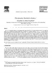
The braking curve of the induction traction motor in metro trains can be divided into three regions: The braking curve of the induction traction motor in metro trains can be divided into three constant torque, constant power and natural characteristics [25], shown as Equation (1) and Figure 2. regions: constant torque, constant power and natural characteristics [25], shown as Equation (1) and Figure 2.
$ ’ &
Ft pvq “ C1 Ft (v) C1 ¨ V “ C2 Ft pvq ’ Ft (v) V2 C2 % Fpvq ¨ V 2 “ C3 t
(1) (1)
Ft (v) V C3
wherewhere C1 , CC21,, and C3 C are constants, Ft (v) is the traction effort and V is the speed of the train. C2, and 3 are constants, F t(v) is the traction effort and V is the speed of the train. P/Ft(v)/Im Um/Il/Be
Constant Torque
Ft ( v )
Constant Power
Natural Characterstics
P
Natural Constant Characterstics Torque
V
Be
Vt 2
Vt1
Im :Current of motor
Im Um
Im
Il
Um
Ft(v):Traction effort
V:Speed
P
Vb
P:Power
Um:Voltage of motor
Il:Current of pantograh Be:Braking effort
Il V
Figure 2. Traction/braking characteristics of metro train.
Figure 2. Traction/braking characteristics of metro train.
Taking trains from the Batong Line of Beijing subway in China as an example, the train brakes using airtrains braking andthe electric braking, includes regenerative braking resistorthe braking. A Taking from Batong Line which of Beijing subway in China as an and example, train brakes brake control unit usually consists of M and T cars, and according to the train braking demand, using air braking and electric braking, which includes regenerative braking and resistor braking. electric braking first. Air brakingofforce willTcompensate substitutetothe electric A brake control unitacts usually consists M and cars, and or according the train braking brakingwhen demand, the electric braking force is insufficient or invalid. electric braking acts first. Air braking force will compensate or substitute the electric braking when the When the electric braking operates, in order to prevent the DC voltage being beyond the electric braking force is insufficient or invalid. permissible range, the controller controls the brake chopper throughout the voltage, across the filter When the electric braking operates, in order to prevent the DC voltage being beyond the capacitor of traction converters, to distribute the regenerative braking and resistor braking power. permissible range, theofcontroller controls the brakeportion chopper throughout voltage, across the filter The working area resistor braking is the shaded in Figure 3. Each the inverter unit is equipped capacitor of traction converters, to distribute the regenerative braking and resistor braking power. with a braking resistor, and the resistance is 1.203 Ω under room temperature. The regenerative The working area of resistor braking is the shaded portion in Figure 3. Each inverter unit is equipped energy will give feedback to the grid first when the train is under electric braking, until the absorption with a braking resistor, and the resistance is 1.203 Ω under room temperature. The regenerative
Energies 2016, 9, 257
4 of 18
Energies 257 4 of 18 energy will2016, give9, feedback to the grid first when the train is under electric braking, until the absorption capacity of 2016, the 9, grid is insufficient. In addition to this, after the grid voltage is increased to 90018V, the Energies capacity of the257grid is insufficient. In addition to this, after the grid voltage is increased to 900 V,4 of the resistor chopper will will be activated. As the voltage gradually increases, thethe chopper working resistor chopper be activated. As grid the grid voltage gradually increases, chopper workingpower capacity of the grid is insufficient. In addition to this, after the gridpower voltage is increased to the 900 V, the gradually vehicle braking at full maximum powerincreases. gradually The increases. The vehicle resistor braking operates resistor operates at full until powerreaching until reaching the resistor chopper will be activated. As the grid voltage gradually increases, the chopper working voltage of 1000voltage V. maximum of 1000 V.
power gradually increases. The vehicle braking resistor operates at full power until reaching the maximum voltage of 1000 V. Maximum braking current Maximum braking current
0
Regenerative braking Regenerative braking 900V
Resistor braking Resistor braking 1000V
VFC
Figure 3. Mixed brake Batong train. 0 1000V 900Vschematic of
VFC Figure 3. Mixed brake schematic of Batong train.
Figure 3. Mixed brake schematic of Batong train. 2.2. Characteristics of the Equivalent 24-Pulse Rectifier
2.2. Characteristics of the Equivalent 24-Pulse Rectifier
The equivalent rectifier unit consists 2.2. Characteristics of 24-pulse the Equivalent 24-Pulse Rectifier of two 12-pulse transformers and rectifiers, and the of the two rectifier transformers are moved +7.5° andtransformers −7.5°, respectively, as shown and in the Thewindings equivalent 24-pulse rectifier unit consists of twoto12-pulse and rectifiers, The equivalent 24-pulse rectifier unit consists of two 12-pulse transformers and rectifiers, and Figureof 4. the two rectifier transformers are moved to +7.5˝ and ´7.5˝ , respectively, as shown in windings the windings of the two rectifier transformers are moved to +7.5° and −7.5°, respectively, as shown in Figure 4. 4. Figure Udc
ea1b1,eb1c1,ec1a1
Phase shifted +7.5°
ea1b1,eb1c1,ec1a1 ea2b2,eb2c2,ec2a2
transformer 1 10kV Eab,Ebc,Eca 10kV Eab,Ebc,Eca
590V
Phase shifted transformer 1
+7.5° Phase shifted transformer 2 Phase shifted transformer 2
590V
Udc
ea2b2,eb2c2,ec2a2 ea3b3,eb3c3,ec3a3 ea3b3,eb3c3,ec3a3 ea4b4,eb4c4,ec4a4
-7.5°
ea4b4,eb4c4,ec4a4 -7.5°
Figure 4. 24-pulse rectifier of the 750 V metro power supply system. Figure 4. 24-pulse rectifier of the 750 V metro power supply system. In multi-pulse rectifier technology, theof output voltage Udc0power of thesupply rectifiersystem. unit is proportional to Figure 4. 24-pulse rectifier the 750 V metro the grid-side no-load voltage [26]. In multi-pulse rectifier technology, the output voltage Udc0 of the rectifier unit is proportional to [26]. P the themulti-pulse grid-side no-load voltage In rectifier technology, ofthe rectifier unit is proportional to output voltage2 U PUdc0 2 P 2U 2 cos d sin cos U d 0 the grid-side no-load voltage [26]. 2 P P U P P 2U cos d 2 PU 2 sin cos 2U 2 NU1 $ (2) d 0 2 π P P ? ’ ` α ’ ? r P P 2PU2 π ’ ’ (2) 2 NU1 “ ’ Ud0“ 2UUcosθdθ sin cosα ’ 2π π ´α U1 2U1N (1 %) ’ π P & P (2) UU (1 voltage, 1%) rectifier output “1N NU 1 In Equation (2),’ U d0 is the no-load P is the number of pulses, U2 is the 2U ’ ’ ’ voltage of the valve’ side, U1 is the line voltage of medium-voltage grid, N is the turns ratio of ’U In Equation (2),’ d0 is the rectifier output no-load voltage, P is the number of pulses, U2 is the transformer primary% to secondary, U1N is U the rating U1Nline p1 `voltage δ%q of medium voltage network and δ is 1 “ voltage of the valve side, U1 is the line voltage of medium-voltage grid, N is the turns ratio of the fluctuation ratio. The output voltage of the 24-pulse rectifier without load can be derived from transformer primary to secondary, U1N isoutput the rating line voltage of medium voltage network and δ isU2 is In Equation Ud0 is the rectifier no-load voltage, P is the number of pulses, Equation (3) as(2), follows: the fluctuation ratio. The output voltage of the 24-pulse rectifier without load can be derived from the voltage of the valve side, U1 is the line voltage of medium-voltage grid, N is the turns ratio of Udc0 1.41NU1 (3) Equation (3) as follows:
transformer primary to secondary, U1N is the rating line voltage of medium voltage network and δ is Udc0DC 1.41 NU1 rectifier As the ratio. load current increases, the output voltage of the equivalent 24-pulse unit the fluctuation The output voltage of the 24-pulse without load can rectifier be derived (3) from reduces accordingly. Equation (3) as follows: As the load current increases, the output DC voltage of the equivalent 24-pulse rectifier unit Udc0 « 1.41NU1 (3) reduces accordingly.
Energies 2016, 9, 257
5 of 18
As the load current increases, the output DC voltage of the equivalent 24-pulse rectifier unit reduces accordingly. Energies 2016, 9, 257characteristic is mainly related to the impedance of the rectifier transformer, 5 of 18 the The external topology of the rectifier circuit, the impedance of the AC power system, the operation status of the The external the Energies 2016, 9, 257 characteristic is mainly related to the impedance of the rectifier transformer, 5 of 18 rectifier, and so on. According to engineering experience, the DC output voltage U status of the 24-pulse topology of the rectifier circuit, the impedance of the AC power system, the operationdc of the rectifier unit can beon. calculated using the following equation The and external characteristic mainly related to the impedance of thevoltage rectifier the rectifier, so According toisengineering experience, the[27]: DC output Udctransformer, of the 24-pulse topologyunit of the circuit,using the impedance of the AC power rectifier canrectifier be calculated the following equation [27]: system, the operation status of the 2 kexperience, Uthe r Ud rectifier, and so on. According to engineering DC output voltage Udc of the 24-pulse (4) n Udc “ Uo ´ k U ˆ U 2 ˆ Isub r equation d n 100 0.9nS rectifier unit can be calculated using the following [27]: T I sub U dc U o (4) 100 0.9nST 2 kside U n Ud is the short-circuit voltage percentile of where Un represents the rating voltage U of theUDC rU d (kV), dI sub (4) o where Un represents the rating voltage dcofthe DC side (kV), is the short-circuit voltage percentile 100 0.9 nSTUn the transformer, ST is the capacity of the transformer (MVA), is the number of 24-pulse rectifier, k is of the transformer, ST is the capacity of the transformer (MVA), n is the number of 24-pulse rectifier, r the coefficient resistance and 0.9and is matching between thethe transformer and n represents the rating voltage of thecoefficient DCcoefficient side (kV), Ud is the short-circuit voltage percentile kwhere r is theU coefficient resistance 0.9 is matching between transformer andrectifier. rectifier. Based on the output and data measured Beijing subway traction substation, of theBased transformer, ST isvoltage the capacity of the transformer (MVA), nthe is the number oftraction 24-pulse rectifier, on the output voltage andcurrent current data measured atat the Beijing subway substation, the output can plotted as shown shownin inFigure Figure 5. kr isoutput thecharacteristics coefficient resistance and 0.9 is matching coefficient the transformer and rectifier. the characteristics canbe be plotted as 5.between Based on the output voltage and current data measured at the Beijing subway traction substation, 外特性曲线 curve characteristic the output characteristics can be plotted asExternal shown in Figure 5. 850
输出直流电压(V) 输出直流电压(V) Voltage (V) Output Voltage Output (V)
外特性曲线 curve External characteristic 800 850 (4185.83,765.95) 750 800 700 750
(4185.83,765.95)
650 700 600 650 0
5000
10000
15000
20000
Output current (A) 输出直流电流(A) 600
5000 character 10000of the 24-pulse 15000 20000 Figure 5.0 The output rectifier.
Figure 5. The output character of the Output current (A) 24-pulse rectifier. 输出直流电流(A)
When the output current approximately 4185.8 the rated output voltage of traction Figure 5.isThe output character of theA, 24-pulse rectifier. When the isoutput approximately the rated output of traction substations 765.9 V,current at whichistime the load rate of4185.8 tractionA, substation is 100%. Thevoltage output voltage When the output current is approximately A,substation the and rated voltage of traction of traction substation decreases asthe theload output current increases, theoutput of the characteristic substations is 765.9 V, at which time rate of 4185.8 traction isslope 100%. The output voltage of substations is 765.9 V, with at which time the load rate of traction substation is 100%. Thecharacteristic output voltagecurve curve changes indecreases pace thethe output current increase. traction substation as output current increases, and the slope of the of traction substation decreases as the output current increases, and the slope of the characteristic changes in pace with the output current increase. curve changes in pace with the output current increase. 3. Wayside Supercapacitor Energy Storage System and Control Strategy
3. Wayside Supercapacitor Energy Storage System and Control Strategy 3. Wayside Supercapacitor Energy Storage System and Control Strategy 3.1. System Components
3.1. System Components The station type supercapacitor ESS consists of a bi-directional DC/DC converter and
3.1. System Components supercapacitor, as shown in Figure 6. The bi-directional DC/DC converter is the key component of the The station type supercapacitor ESS consists of a bi-directional DC/DC converter and station type supercapacitor ESS voltage consists of shift a bi-directional DC/DC converter and wholeThe system, undertaking the tasks of system level and energy management. supercapacitor, as as shown The bi-directional DC/DC converter the key component supercapacitor, shownin in Figure Figure 6.6.The bi-directional DC/DC converter is the keyiscomponent of the inet of system voltage level shift and energy management. R of thewhole whole system, undertaking the tasks net system, undertaking the tasks of system voltage level shift and energy management. Rnet iiCnet U net
+ UicC
T1 T1
-
U net
+ Uc
C
-
+
C
T2
+
UL L UL L
-
iL U uc
iL U uc
T2 system based on half-bridge topology. Figure 6. Supercapacitor storage
DependingFigure onFigure different conditions of the traction substation, the supercapacitor ESS will operate Supercapacitor storage system based half-bridge topology. 6. 6. Supercapacitor storage system basedonon half-bridge topology. when in charging or discharging status, the bidirectional DC/DC converter through control T1 and T2 Depending on different conditions of the traction substation, the supercapacitor ESS will operate switching to realize supercapacitor’s charging or discharging, thus achieving the different directions Depending on different conditions ofthe the traction substation, the supercapacitor ESST1will operate when in charging or discharging status, bidirectional DC/DC converter through control andthe T2 of chopping inductor current iL. Operating in either the charging or discharging status, whensupercapacitor in charging or discharging status, the bidirectional DC/DC converter through control T and T2 1 switching to realize supercapacitor’s charging or discharging, thus achieving the different directions ESS can be represented using the unified model shown in Figure 7, where Ron is the of chopping inductor current iL. Operating in either the charging or discharging status, the supercapacitor ESS can be represented using the unified model shown in Figure 7, where Ron is the
Energies 2016, 9, 257
6 of 18
switching to realize supercapacitor’s charging or discharging, thus achieving the different directions of chopping inductor current iL . Operating in either the charging or discharging status, the supercapacitor Energies 9, 257 of 18 ESS can be 2016, represented using the unified model shown in Figure 7, where Ron is the on-state 6resistance 6 of 18 of theEnergies IGBT,2016, RL 9,is257 the equivalent resistance of the chopping inductor, Rnet is the equivalent resistance on-state resistance of the IGBT, RL is the equivalent resistance of the chopping inductor, Rnet is the of theequivalent input side, and R is the ESR of the supercapacitor. resistanceucof the input side, and Ruc is the ESR of the supercapacitor. on-state resistance of the IGBT, RL is the equivalent resistance of the chopping inductor, Rnet is the equivalent resistance of the input side, and Ruc is the ESR of the supercapacitor. R i net
Rnet inet
net
Rnet inet iC iC +
U net
Ron +
Uc
C
-+ U
U net
Rnet inet iC
Ron
RL
C
c
+
iC +
U net
-
LL U
RL
-
-
UL
Uc
U net
L
+ C
-+
Uc
U uc
C
-
RL
+
RonR
-
UL
- i L
LL U
Ruc + iL U uc Ruc -+ U uc
L
L
Ron
U uc 0