paper, we propose a nonlinear multi-user MIMO cooperative downlink transmission scheme. The algorithm eliminates the interference and achieves symbol ...
This full text paper was peer reviewed at the direction of IEEE Communications Society subject matter experts for publication in the IEEE ICC 2009 proceedings
Cooperative Precoding and Beamforming for Co-existing Multi-User MIMO Systems Wibowo Hardjawana∗ , Branka Vucetic and Yonghui Li Telecommunications Lab, School of Electrical and Information Engineering The University of Sydney, Australia {whar5698∗ ,branka,lyh}@ee.usyd.edu.au A BSTRACT Interference among multiple base stations that co-exist in the same location limits the capacity of wireless networks. In this paper, we propose a nonlinear multi-user MIMO cooperative downlink transmission scheme. The algorithm eliminates the interference and achieves symbol error rate (SER) fairness among different users. To eliminate the interference, Tomlinson Harashima precoding (THP) is used to cancel part of the interference while the transmit-receive antenna weights cancel the remaining part. The uplink-downlink duality principle is used to calculate transmit-receive antenna weights. The proposed scheme is then extended to work when the receiver does not have complete Channel State Informations (CSIs). The simulation results show that the proposed schemes considerably outperform existing cooperative transmission schemes in terms of SER performance and approach an interference free performance under the same configuration.
I. I NTRODUCTION The spectral efficiency of existing cellular networks and wireless local area networks (WLANs) is limited by interference. In cellular mobile networks, the dominant interference comes from adjacent cells, while in co-working WLANs, the interference from other networks, operating in the same area, is a major limiting factor. In this paper, we consider a cooperative transmission scheme for multi-user MIMO systems where each base station (BS) collaborates to transmit a symbol to its respective mobile station (MS) simultaneously using same frequency band and time slots. A multi-user multiple-input-multiple-output (MIMO) system with multiple transmit-receive antennas has been considered by several researchers. In [1], the authors used the uplinkdownlink duality concept introduced in [2], [3] for a single receive antenna scenario, to iteratively design the optimum downlink transmit-receive weights and downlink transmission powers in a multi-user MIMO system with multiple transmitreceive antennas. In [4], the authors showed how a zero forcing (ZF) method can be used in a multi-user MIMO system. Nonlinear methods utilizing a combination of the ZF method with dirty paper coding (DPC) [5] and a combination of the ZF method with THP [6], [7] for a multiuser MIMO system was considered in [8], [9], respectively. The authors use the ZF method to eliminate part of the inter-link interference. DPC or THP are then used to cancel
the remaining interference. These schemes, however, are not practical for cooperative MIMO systems since their symbolerror-rate (SER) performance varies from user to user. In particular, this SER variation is not desirable since the MIMO sytems can be deployed by different operators and they expect the systems to have similar performance. In this paper, we exploit the uplink-downlink duality concept [2], [3] to design a cooperative transmission scheme employing nonlinear precoding and beamforming for the downlink of a multi-user MIMO system. In the proposed scheme, THP [6], [7] cancels part of the interference. The remaining interference is suppressed by using transmit-receive antennas weights. We relax the zero forcing and orthogonality constraints for transmit weights vectors compared to those in [4], [8], [9] when designing transmit-receive weights. In addition, we also eliminate the iterative process to find transmit-receive weights in [1]–[3] when the uplink-downlink duality concept is used. To maintain SER fairness among users, downlink powers are allocated such that the downlink signal-interference-plusnoise ratio (SINR) for users are equal. Furthermore, we extend the proposed scheme to work when the receiver does not have a complete channel state information (CSI) and the system does not allow BSs to specifically send receive weights information to each receiver. That is, each MS receiver only knows its own CSI, making a joint design of transmit-receive antenna weights impossible. To further improve system performance, we develop an adaptive precoding order (APO) for users based on the user ordering detection method in [9], [10]. The remainder of this paper is organized as follows. Section II presents the system model. The design of the joint transmitreceive weights vectors is introduced in Section III. Section IV shows how to allocate power such that SER performances for every users are identical. Section V shows how to extend the proposed method to work when full CSI is not available at the MSs. Section VI describe how to use VBLAST ordering to order users at the transmitter. Section VII shows the simulation results. The notations used in the paper are as follows. We use boldface lower case letters to denote vectors and boldface upper case letters to denote matrices. The superscripts .H , .T , I and Diag() denote the conjugate transpose, transpose, an identity matrix, and a diagonal matrix, respectively. C a×b indicates a complex matrix with a rows and b columns. �x�, � · � and | · | are the greatest integer smaller than x, the Euclidean distance and the absolute value, respectively.
978-1-4244-3435-0/09/$25.00 ©2009 IEEE
This full text paper was peer reviewed at the direction of IEEE Communications Society subject matter experts for publication in the IEEE ICC 2009 proceedings
LoT (A), U pT (A) and DiT (A) are defined as the operation to extract the lower triangular, upper triangular and diagonal components of A. [A]l,˙ ¨l denotes the component of matrix A located in row l˙ and column ¨l. Lastly, we define 1 as a column vector with all entries equal to 1. II. S YSTEM M ODEL In this paper, we consider multi-user MIMO systems, where K BSs transmit symbol streams to K MSs. Each BS and MS is equipped with NBSk and NM Sk antennas, for k = 1, ..., K, respectively. All BSs cooperate with each other to transmit to �k=K their respective MSs via N BS = k=1 NBSk antennas. Each of these transmissions is defined as a link. A. Transmitter Structure The transmitter for the proposed cooperative transmission with precoding and beamforming is shown in Fig. 1(a). Let xk represents a M -QAM (M -ary Quadrature Amplitude Modulation) modulated symbol, intended for transmission from BS k to MS k. The modulated symbols for K MSs can then be written as x = [x1 · · · xK ]T . The transmitted symbols for each user are first permuted by a block diagonal permutation matrix Mperm = Diag(m1 , ..., mK ) where mi=1,...,K = 1. This permutation operation is referred to as the adaptive precoding order (APO). The APO adaptively selects the precoding order of x that maximizes the minimum SINR of K users. It selects a suitable permutation matrix Mperm to permute x. Let u = Mperm x = [u1 · · · uj · · · uK ]T be the permuted transmitted symbol vector. Thus, after the APO, xk for MS k is permuted into uj , which will be transmitted in link j. Let us assume initially that we do not use the THP scheme. Thus, we omit THP precoding and decoding in Fig. 1. The power allocation module then allocates powers to each link such that the received SINRs for all KS links are equal. This is done by multiplying u with the matrix, √ √ P = Diag( p1 , ..., pK ) where pj is the downlink power allocated to link j. The signal for K links is then given as Pu. The interference in each link then needs to be suppressed by multiplying the signal from each link by the transmit antenna weights vectors of all BSs, denoted by T, where T ∈ C N BS ×K and by the receive antenna weights at the receiver of link j, denoted by rj , where rj ∈ C NM Sj . The transmitted signal, thus is given as xT = TPu. B. Receiver Structure The receiver for each link is shown in Fig. 1(b). Note that there is no cooperation among the receivers. We first denote the received signal matrix for each link as yj where yj ∈ C NM Sj . The received signal matrix for K links, denoted by y, y = [y1 ...yK ]T , can be written as y = HTPu+N where H = [H1 ...Hj ...HK ]T , N = [n1 , ..., nK ]T . nj ∈ C NM Sj is the noise vector for link j. T = [t1 ...tK ] ∈ C N BS ×K and Hj are the transmit weights vectors for K links and the channels matrix for link j, respectively. After multiplying y by the receive weights matrix R, the received signal vector becomes y = RHTPu + RN = (D + F + B)Pu + RN
(1)
H where R = Diag(rH 1 , ..., rK ), D = DiT (RHT), B = U pT (RHT), F = LoT (RHT) and y = [y 1 ...y j ...y K ]T . y j is the received signal at the input of the THP decoder for link j. rj is the receive antenna weights vector for link j. DPu is a vector of scaled replicas of the transmitted symbols for K links. FP is defined as the front-channel interference matrix, since the rows j = 1, ...K of FP represent the interference caused by links 1, .., j − 1. Similarly, BP is defined as the rear-channel interference matrix, since the rows j = 1, ...K of BP represent the interference caused by rear links j + 1, .., K.
C. THP Precoding Structure Note that here, the transmit-receive weights vectors for link j are used to suppress the interference in link j coming from link 1, ..., j − 1, j + 1, ..., K. To further improve system performance, we can pre-subtract some of the interference prior to transmission. Because of this, the transmit-receive weights matrix now needs to suppress less interference. In this paper, we will use the THP scheme proposed in [6], [7] and choose to pre-subtract the front-channel interference FP. Thus, now, prior to the power allocation module, THP precodes u into v = [v1 · · · vj · · · vK ]T ∈ C K . The frontchannel interference is then subtracted from u as in [9], ˜ + MT HP v v = u + d − (DP)−1 FPv = v
(2)
where (DP)−1 is used to normalize the front-channel inter√ ference with respect to u. d = [d1 ...dK ]T , dj = 2 M Δ and Δ is a complex number whose real and imaginary parts are suitable integers selected to ensure √ the√real and imaginary parts of vj are constrained into (− M , M ]. Here, we use the vector as an offset to ensure the energy of v to be between √ d√ (− M , M ], since the value of v after pre-subtraction of the√front-channel interference can be very large and exceed √ (− M , M ]. By using a modulo operation, defined as [9] √ √ M √ )/ M � (3) modM (uj ) = uj − M �(uj + 2 for j = 1, ..., K, the output of the � THP precoder in (2) can j−1 be re-written as vj = modM (uj − l=1 [MT HP ]j,l vj ), j = 1, .., K where [MT HP ]j,l denotes the (j, l)th component of MT HP . Since now we are using the THP scheme, we are transmitting THP precoded symbol streams, v instead of u. The received signal y is now given by (1) with u is replaced by v. By using (1) and (2), the received signal is now given as y = (D + F)Pv + BPv + RN = DP˜ v + BPv + RN. (4) The estimates of the transmitted symbols for link j, denoted by u ˆj , can be recovered from y j , by applying an element-wise ˆj = modM (y j ) , j = modulo operator in (3) to each y s,j , as u 1, ..., K. Here, the effect of offset vector d on the desired transmitted signal is removed at each MS receiver by applying the modulo operation in (3) to each y j in (4). This is shown in Fig. 1(b). In the proposed scheme, THP cancels the interference caused by the front-channel interference, while the interference
This full text paper was peer reviewed at the direction of IEEE Communications Society subject matter experts for publication in the IEEE ICC 2009 proceedings
Fig. 1: (a) Nonlinear Cooperative Precoding Transmitter Structure, (b) Receiver Structure
caused by the rear-channel interference is eliminated by the transmit-receive antenna weights optimization process. III. T RANSMIT-R ECEIVE W EIGHTS O PTIMIZATION In this section, we propose a joint transmit-receive antenna weights optimization method to cancel the rear-channel interference, while maximizing the SINR for each link and maintaining the same SER for all links at all times. To do this, we use the fact that 1) we can set E[vvH ] = E[uuH ] = I and 2) the effect of vector d on the received signals is completely removed by the THP decoder modulo operation. By using (4), the received downlink SINR for each link j can then be written as H pj rH j Hj tj (Hj tj ) rj (5) SIN Rjdown = �K H 2 i=j+1 pi �ri Hj ti � + σ where σ is MS receiver noise. The operation of maximizing the minimum SINR for each link, while maintaining it equal for all links, can be formulated as follows max min SIN Rjdown rj , tj , pj H T s. t. (1) tH j tj = 1, (2) rj rj = 1 , (3) 1 p = Pmax (6)
for j = 1, ..., K. Pmax and p = P2 1 are the power constraint at the cooperative transmitter and the set of downlink powers assigned to each link, respectively. The first, second and third constraints in (6) will bound the possible solution for R, T, and P and ensure the convergence of (6) to a solution. It is obvious that the optimal solution is reached when all links attain equal SINR, denoted by SIN Rdown . In this paper, we want to use the uplink-downlink duality concept for designing the transmit-receive weights. In addition, we also want to eliminate the iteration process required for finding the transmit weights as in [1]. To apply the duality concept, we create a virtual uplink and swap the role of the transmitter and the receiver. In the virtual uplink, the receiver of a MS acts as a transmitter. The MS previously ordered in link j, now transmits a virtual symbol u ˇj in link j using its receive weights vector (e.g., rj ) to the BSs. To eliminate the iterative requirement, we set the virtual uplink power for link j = 1, ..., K, qj to be equal. For simplicity, we assume, Pmax = K. Thus we have Q = Diag(q1 ...qK ) = I. Here, by fixing the virtual uplink power Q = I, we do not need to find the uplink power iteratively. The BSs then act as a
single cooperative receiver and process the signal by using its transmit weights vectors (e.g., T). We let the virtual received ˇ up = [ˇ y1 ...ˇ yK ]T where yˇj is the received signal at the BSs be y signal in link j and let the transmitted symbols for K links ˇ = [ˇ uK ]T . By using (4), the virtual received uplink be u u1 ...ˇ signal can then be written as H ˘ ˇ + Diag(TH ˇ up = Dˇ u + BH u y 1 , ..., TK )N
(7)
˘ = [˘ ˘ j ∈ C N BS is the virtual receiver nK ]T and n where N n1 ...˘ noise for link j at BSs, modelled as an AWGN with a zero mean and the variance σ 2 . The virtual uplink configuration is shown by broken arrows in Fig. 1. By using (7), the virtual uplink SINR for each link, can be written as H H H tH j Hj rj (Hj rj ) tj SIN Rjup = �j−1 H H 2 i=1 �tj Hi ri � + σ
(8)
for j = 1, ..., K. There are two terms in the denumerator of (8). The first and second terms denote the inter-link interference and the AWGN noise, respectively. The optimization problem can then be written as max min SIN Rjup rj , tj s. t.
H (1) tH j tj = 1, (2) rj rj = 1
(9)
for j = 1, ..., K. Here, the optimal solution is reached when all links attain equal SINR, denoted by SIN Rup . To solve (9), we first create a transmission space that has the minimum sum of the inter-link interference and receiver noise. We need to find orthonormal vectors that maximize (8). By denoting these orthonormal vectors as ¯tj , we can write this problem as max ¯ tj
H H H¯ ¯tH j Hj (Hj ) tj ¯ j tH ¯tj R j
(10)
¯ j = �j−1 HH ri (HH ri )H + σ 2 I is the summation where R i i i=1 of the inter-link interference and the AWGN in link j. (10) is a standard generalized eigenvalue problem and can be solved using standard methods [11], ¯ ¯ ¯ HH j Hj tj = λj Rj tj ¯ −1 H ¯ HH ¯ j. R j j
(11)
We then where λj is the largest eigenvalue of project the channel Hj into the transmission space for link j, ˆ j = Hj T ¯ j . Singular Value ¯tj to obtain an effective channel, H
This full text paper was peer reviewed at the direction of IEEE Communications Society subject matter experts for publication in the IEEE ICC 2009 proceedings
ˆ j to find Decomposition (SVD) [11] is then performed on H the suitable transmit-receive weight vectors for each link, ˆ j ), j = 1, ..., K. (rj , tj ) = SV D(H
(12)
By using (12), the receive weights, rj and the transmit weights, tj can be obtained by selecting a left and a right eigenvector that correspond to the maximum eigenvalue of ˆ H , respectively. To solve (10), however, we also need ˆ jH H j to know ri=1,...,j−1 . We utilize the fact that link 1 does not have any interference coming from other links. Thus, we start by designing the transmission space and the transmitreceive weights vectors for the first link. We then design the transmission space and the transmit-receive weights vectors for the second link by treating the first link as interference and so on. IV. P OWER A LLOCATION In this section, we use the calculated R and T to find p so that the downlink SINRs for all links are equalized. We let ˜ ˜ ˙ ¨, l˙ = ¨l = 1, ..., K be (l,˙ ¨l)th component of matrix M [M] l,l T ¯ ¯ ¯ ˜ ¯ ¯ where M = DiT (RHT) + U pT (RHT), H = [H1 ...HK ] . We first define 1T p = Pmax and the extended downlink power vector as pe = [pT 1]T . Now, by rearranging (5) and by multiplying both sides of (5) with 1T , we can obtain an equations matrix given as [2] pe (13) Ψpe = SIN Rdown where � � A−1 1 A−1 B . (14) Ψ= 1T A−1 B/Pmax 1T A−1 1/Pmax where A = DiT (M), B = U pT (M) and M is a KS by KS ˜ 2 . Hence the matrix with its component [M]l,˙ ¨l equal to [M] ˙¨ l, l optimum virtual uplink power p can be obtained by selecting pe that corresponds to the maximum eigenvalue of Ψ. This is the only possible solution for (13) satisfying pj ≥ 0 for j = 1, ..., K and SIN Rdown ≥ 0. The proof is described in detail in Theorem 1 and 2 of [12]. We refer to the combination of the joint transmit-receive weights optimization, the power allocation, APO, and THP precoding as AI-APO-Full CSI. V. I NCOMPLETE CSI AT THE RECEIVER AI-APO-Full CSI works by jointly designing R and T. This joint design process requires MSs to either 1) know the complete CSI, Hi=1,...,K to be able to design R or 2) receive the information about R from BSs. This condition increases the network cost and reduces its spectral efficiency. In this section, we aim to eliminate the requirement for a complete CSI for the proposed scheme by separating the design of R and T. We use the following assumptions 1) if each MS k knows its own Hk , we can independently design the receive weights vector for each symbol. 2) If BSs know all CSIs, Hk=1,...,K , BSs know the receive weights vectors used by MSs. Here, we observe that the number of receive weights vectors, available for each link, depends on the rank of Hj ,
˜ Thus, rj can be selected from S˜ possible receive weight S. vectors. This can be done easily by performing SVD on Hj and by extracting all left eigenvectors from Hj . We want to utilize this fact to obtain a better performance. We will select the combination of transmit and receive weights that gives the maximum gain ˆH ˜ = 1, ..., S˜ max �rH s˜,j Hs,j ts˜,j � , s
rs˜,j ,ts˜,j
(15)
where each ts˜,j is computed for a fixed rs˜,j and rs˜,j is s˜th vector selected from S˜ possible receive weight vectors. To compute the transmit weight vector, ts˜,j for a fixed rs˜,j , we H first replace HH j in (10) with Hj rs˜,j . We then use (11) and (12) to find the transmit weight vector. We repeat this process until all ts˜,j , s˜ = 1, ..., S˜ are found. We then apply (15) to find the best transmit-receive weights vectors. We refer to the combination of the transmit-receive weights optimization described in this section, the power allocation in Section IV, APO, and THP precoding as AI-APO-Incomplete CSI. VI. A DAPTIVE P RECODING O RDER Here, we describe how APO can be implemented. We first note that the performance of the system differs when a different Mperm is used. Thus, APO arranges the order of x by selecting Mperm that maximizes the downlink SINR. This problem can be formulated as follows, Mperm =
max min
Mperm ,j=1,...,K
SIN Rjdown (Mperm )
(16)
where SIN Rj (Mperm ) is the SINR of link j, given that the permutation matrix Mperm is used. To solve (16) without searching from K! possible orderings, we use the idea of the Myopic Optimization method proposed in [10], which is proven to be optimal. By applying this idea to the second optimization problem in (16), we only need to search �K−1 i=0,i�=1 K − i possible orderings. VII. N UMERICAL R ESULTS AND D ISCUSSION Monte Carlo simulations have been carried out to assess the performance of the proposed algorithm. We investigate their performance and compare it with [4], [8], [9] and with an interference free performance. Here, an interference free performance is defined as the performance of any random single link i assuming there is no interference from other links at all. In this case, the received signal of the cooperative transmission system is given as yi = rH i (Hi ti xi + ni ) where ri and ti are the left and right eigenvectors associated found by using with the maximum eigenvalue of Hi HH i the Singular Value Decomposition (SVD). We will use the notations (N BS , NM S , K) in all figures to denote the number of transmit antennas of BSs, the number of receive antennas per MS, the number of users, and the number of symbols transmitted per user in the network, respectively. We also assume NM Si=1,...,K = NM S for simplicity. A Rectangular 64-QAM (M=64) modulation is used for all transmissions. To simulate the wireless channel, we set the elements of each Hj channel matrix as a complex Gaussian variable with
This full text paper was peer reviewed at the direction of IEEE Communications Society subject matter experts for publication in the IEEE ICC 2009 proceedings
receiver to work.
0
10
VIII. C ONCLUSION −1
Symbol Error Rate (SER)
10
−2
10
−3
10
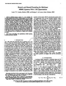
AI−VBLAST−Full CSI Scheme in [8,9] Scheme in [4] AI−VBLAST−Incomplete CSI Interference free
−4
10
12
14
16
18 SNR
20
22
24
Fig. 2: Average SER for (6,2,3,1) Systems
a zero mean and unit variance. In all simulations, we fix the Signal-to-Noise-Ratio of each THP precoded symbol to 2E[v 2 ] be SN R = σ2 j , where E[vj2 ] is normalized to 1 and Pmax = K. We study the performance of individual link SER and the overall SER. The overall SER is defined as the average SER of K links. We consider a (6, 2, 3) system. Due to space limitation, we do not show the performance of individual link SER in this paper. Our simulation results for each link confirm that both AI-APO-Full CSI and AI-APO-Incomplete CSI produce an almost equal SER performance for all their three links. In Fig. 2, the overall SER performances for the proposed schemes are compared with other existing schemes at SER=10−5 . We compare the proposed algorithm with those in [4], [8], [9]. As [4] is a linear interference cancellation scheme, we modify it to work with THP. In addition, to have a fair comparison with the proposed method, a power allocation scheme that allocates power such that SINRs for all links are equalized [13], is applied to schemes in [4], [8], [9]. This is because, the water-filling power allocation used in [4], [8], [9] tends to assign more power to stronger links and less power to weaker links. Hence, the performance of a weaker link will decrease the overall SINR for all links. As can also be seen from Fig. 2, the proposed algorithms, denoted by AI-APO-Full CSI and AI-APO-Incomplete CSI, significantly outperform the existing schemes. Its performance outperform the schemes in [4], [8], [9] by more than 4 dB and 2 dB, respectively. In addition, the performance of AI-APOFull CSI is 0.5 dB away from an interference free performance. These two algorithms outperform the scheme in [4], [8], [9] by more than 4 dB and 2 dB, respectively. The performance of AIAPO-Incomplete CSI is only 0.8 dB away from an interference free channel and still outperforms the scheme in [4] by 1.5 dB and the scheme in [8], [9] by 3 dB. This is a definite advantage since the schemes in [4], [8], [9] need complete CSI at the
In this paper, we exploit the uplink-downlink duality concept to design a cooperative multi-user MIMO downlink transmission scheme employing precoding and beamforming. THP and transmit-receive weights optimization are used to cancel the interference. Power allocation and APO are applied to achieve symbol error rate (SER) fairness among different users and further improve the system performance, respectively. We proposed a method that eliminate the iterative process required to find the transmit-receive weights when uplink-downlink duality concept is used. We then extend this method to work in a situation where each receiver only knows its own CSI. The error performance for a (6, 2, 3, 1) cooperative system is shown. The proposed method outperforms the existing schemes by at least 2 dB and is only 0.5 dB away from an interference free performance for SER=10−5 . Thus, the proposed method is an attractive solution for improving the performance and capacity of co-working WLANs and cellular mobile networks. R EFERENCES [1] C. Jae-Hwan, L. Tassiulas, and F. Rashid-Farrokhi, “Joint transmitter receiver diversity for efficient space division multiaccess,” IEEE Trans. Wireless Commun., vol. 1, no. 1, pp. 16–27, 2002. [2] M. Schubert and H. Boche, “Solution of the multiuser downlink beamforming problem with individual sinr constraints,” IEEE Trans. Veh. Technol., vol. 53, no. 1, pp. 18–28, 2004. [3] F. Rashid-Farrokhi, K. J. R. Liu, and L. Tassiulas, “Transmit beamforming and power control for cellular wireless systems,” IEEE Trans. Commun., vol. 16, no. 8, pp. 1437–1450, 1998. [4] Q. H. Spencer, A. L. Swindlehurst, and M. Haardt, “Zero-forcing methods for downlink spatial multiplexing in multiuser mimo channels,” IEEE Transaction on Signal Processing, vol. 52, no. 2, pp. 461–471, 2004. [5] M. H. M. Costa, “Writing on dirty paper,” IEEE Transaction on Information Theory, vol. 29, no. 3, pp. 439–441, 1983. [6] M. Tomlinson, “New automatic equalizer employing modulo arithmetic,” IEEE Elec. Lett., vol. 7, pp. 138–139, 1971. [7] M. Miyakawa and H. Harashima, “A method of code conversion for a digital communication channel with intersymbol interference,” IECE Trans., vol. 52-A, pp. 272–273, 1971. [8] G. J. Foschini, K. Karakayali, and R. A. Valenzuela, “Coordinating multiple antenna cellular networks to achieve enormous spectral efficiency,” IEEE Proc. on Communications, vol. 153, no. 4, pp. 548–555, 2006. [9] J. Liu and A. K. Witold, “A novel nonlinear joint transmitter-receiver processing algorithm for the downlink of multi-user mimo systems,” IEEE Trans. Veh. Technol., accepted,2007. [10] G. J. Foschini, G. D. Golden, V. R. A., and W. P. W., “Simplified processing for high spectral efficiency wireless communication employing multi-element arrays,” vol. 17, no. 11, pp. 1841–1852, 1999. [11] J. R. Schott, Matrix Analysis for Statistics. John Wiley and Sons, Inc, 1997. [12] W. Yang and G. Xu, “Optimal downlink power assignment for smart antenna systems,” in IEEE International Conference on Accoustic, Speech, and Signal Processing (ICASSP), vol. 6, 1998, pp. 3337–3340. [13] D. Palomar, J. Cioffi, and M. Lagunas, “Joint tx-rx beamforming design for multicarrier mimo channels: A unified framework for convex optimization,” IEEE Trans. Commun., vol. 51, no. 9, pp. 2381–2401, 2003.