Cooperative Spectrum Sensing with Optimal Sensing Ranges in Cognitive Radio Ad-Hoc Networks Jongwon Shim
Qi Cheng
Venkatesh Sarangan
Department of Computer Science Oklahoma State University Stillwater, Oklahoma 74078 Email:
[email protected]
School of Electrical and Computer Engineering Oklahoma State University Stillwater, Oklahoma 74078 Email:
[email protected]
Department of Computer Science Oklahoma State University Stillwater, Okalahoma 74078 Email:
[email protected]
Abstract—Cognitive radio has been proposed as an innovative and effective technology to exploit the efficient reuse of the precious radio spectrum. In spectrum sensing which is a crucial step in cognitive radio networks, an adequate sensing range needs to be defined to prevent the hidden transmitter/receiver problems. Moreover, a secondary user may have unreliable detection of the existent primary users due to channel fading and/or shadowing. To overcome these problems, cooperative spectrum sensing may be adopted. In this paper, we propose a cooperative spectrum sensing scheme with adaptive sensing ranges in cognitive radio ad-hoc networks. We explain the adaptive sensing range of a local secondary user transmitter and analytically show that cooperative spectrum sensing with adaptive sensing ranges is better than that with a fixed sensing range.
I. I NTRODUCTION With the growing interest of the users in wireless networks in recent years, spectrum resources are confronting tremendous demands. Conventionally, the radio spectrum is a limited natural resource and is regulated and licensed to users by government agencies such as the Federal Communication Commission (FCC) in the United States. Frequency bands have been exclusively allocated to specific services and users, and the systems are protected by this traditional policy for many years. However this fixed spectrum management has led to spectrum scarcity and inefficient spectrum utilization. Recent observations by FCC show that 70% of the allocated spectrum in US is underutilized [1]. Thus, it becomes obvious that the fixed spectrum management is not suitable for current wireless applications and services. To mitigate this spectrum limitation, recently FCC has suggested a new paradigm for dynamically allocating the spectrum portions assigned to the licensed users but not used at specific time and locations [2]. This is the basis of the cognitive radio (CR). Cognitive radio has been proposed as an innovative and effective technology to exploit the efficient reuse of the precious radio spectrum. With the cognitive radio technology, secondary users (SU) who do not hold the license can opportunistically access the under-utilized licensed spectrum without causing interference to the primary users (PU). To do this, secondary users dynamically sense, identify, and then
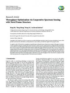
operate in the unused frequency bands. However, secondary users quickly vacate the frequency band when the primary user wants to use its licensed spectrum again. Therefore, the overall spectrum utilization can be effectively improved with the cognitive radio technology. Especially, CR networks are inherently multi-channel, since these networks operate over a set of channels whose availability changes over time. The availability of channels may vary widely from node to node in CR networks. Multi-channel MAC protocols have advantages such as reducing interference among the nodes and increasing the capacity of the wireless network significantly by simultaneously operating over multiple channels even if each node occupies one channel at a time. When we design an effective cognitive radio MAC protocol, there are three possible sources of detection errors that need to be considered [3]: hidden transmitter (node X), hidden receiver (node Y), and exposed transmitter (node Z) as shown in Fig.1. Generally, node A cannot distinguish the exposed transmitter and other transmitters when node A conducts spectrum sensing. Therefore, this paper does not consider this exposed transmitter problem. In [4], the concepts of the transmission range, the sensing range, and the interference range are explained for IEEE 802.11 in detail.
Z X
RS Ri
A d B
Ri Y Primary Tx Primary Rx
Fig. 1.
Spectrum opportunity detection
Moreover, there are many new challenges associated with CR networks, such as receiver uncertainty/shadowing uncertainty problems [5]. A secondary user may suffer from unexpected multipath fading and/or shadowing when sensing the signal from a particular primary transmitter. To account for possible losses due to multipath fading and shadowing, the secondary user must be significantly more sensitive in detecting the primary user’s signal. In addition, existing problems in conventional multi-channel wireless networks such as multichannel hidden terminal problem still remain unsolved even though CR-enabled devices are deployed. In this paper, to tackle these problems, we propose a cognitive radio MAC protocol, which integrates the cooperative spectrum sensing at SU transmitters and the local spectrum sensing at SU receivers with adaptive sensing ranges. This paper makes the following contributions: 1) Propose the solution for the hidden receiver problem using cooperative spectrum sensing at one SU transmitter with cooperative partners using adaptive spectrum sensing ranges. Basically, this cooperative spectrum sensing can help solve receiver uncertainty/shadowing uncertainty problems, and mitigate the multipath fading and shadowing effects and improve the detection probability in a heavily shadowed environment. 2) Propose the solution for the hidden transmitter problem using local spectrum sensing at one SU receiver with an adaptive spectrum sensing range. The rest of this paper is organized as follows: Section II presents an SIR-based model that is used for interference analysis. Section III presents the solution for the hidden transmitter problem and the solution for the hidden receiver problem. Conclusions and the future work are provided in Section IV.
B. The Signal to Interference Ratio Model When a signal is propagated from a transmitter to a receiver, successful reception of a packet at the physical layer depends on the signal to interference ratio at the receiver. We assume that the radio propagation model in this paper is the large scale path loss model [6]. For simplicity, we assume that the transmission power and the hardware at every node are all the same. This implies that the transmission range of all transmitters is the same. Given the transmission power, the receiving power is mostly decided by the path loss over the transmitter-receiver distance. This large scale path loss model is commonly used to explain the radio propagation property in wireless networks [7]. To calculate the interference range, we only consider the signal attenuation caused by the path loss. According to this model, the received power at distance d is given by h2t h2r (1) dα where Pt is the transmitted power, ht and hr are the height of the transmitter and receiver antennas respectively, Gt and Gr are the antenna gains, d is the distance between the transmitter and the receiver. α is the signal attenuation coefficient (path loss exponent) which reflects how fast the signal attenuates. We assume that ad-hoc network is homogeneous, that is, all the radio parameters are the same at each node. To obtain the value of the interference range, Ri , we need to introduce the model of signal to interference ratio (SIR). Now, we assume a transmission is going from a transmitter to a receiver in a distance d meters and at the same time, an interfering node r meters away from the receiver starts another transmission. Let Pr denote the receiving power of the signal from the transmitter and Pi denote the power of the interference signal at the receiver. Then SIR is given as SIR = Pr /Pi . Neglecting the thermal noise, we can get [8][9] Pr = Pt Gt Gr
II. IEEE 802.11 BASED A D -H OC N ETWORKS A. Problems of IEEE 802.11 DCF in Ad-Hoc Networks
h2t h2r ( )2 Pr dα = r ≥ S SIR = = (2) 0 2 2 Pi d ht h r Pt Gt Gr α r where S0 denotes the capture threshold value for a correct reception, which in practice is usually set to 10dB as in the 802.11b specification and α is equal to 4 in the two-ray ground reflection model and is equal to 2 in a free space model. To prevent the interference at the receiver, SIR should be equal to or greater than the capture threshold. In other words, this implies that to √ successfully receive a signal, the interfering nodes must be α S0 meters away from the receiver. Thus, the interference range is give by [4][9][10]
In wireless networks, interference depends on the location. The interference range can be defined as the range within which the station in a receiving mode will be interfered with by other transmitters and thus suffer a loss. This range is actually not a fixed value due to the capture effect [4]. All nodes located in the interference range can create interference at the receiver. Thus, the hidden terminal problem may take place frequently based on the locations of nodes. The RTS/CTS handshake is designed mainly for this purpose. In this case, there is a basic assumption that all hidden nodes are within the transmission range of the receiver. However, some nodes which are out of the transmission range of both the transmitter and the receiver may still interfere with the receiver. This situation hardly occurs in the infrastructure WLAN because most nodes are in the transmission range of either transmitters or receivers. However, this situation can make a serious problem in ad-hoc networks due to the wide distribution of node and the multihop operation.
Pt Gt Gr
√ α S0 × d = γ × d (3) √ where γ is defined as α S0 . We notice that there is no fixed relation between the interference range and the transmission Ri =
2
range. Ri is proportional to the one-hop distance d. In addition, we can define the transmission range and the sensing range [10]. The transmission range, Rt , is given by ( Rt = d
P rx PR
Rt
) α1
Ri
(4)
d E
A
B
where P rx is the reference signal strength as measured at the distance d (usually 1 meter) and PR is the reception power threshold. The sensing range is given by ( Rs = d
P rx PC
F Int erf ere nc e
C
) α1
D
(5)
A, C, D, E, F: Transmitter B: Receiver
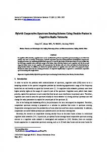
where PC denotes the carrier sensing threshold. The concepts of the interference range and the transmission range are illustrated in Fig.2. Note that Rt and Rs are merely radio ranges, which implies that they only apply in the physical layer. However, Ri is involved in the SIR model and the comparison of the received power, so it should be managed at the MAC layer as well. We can see that when the transmitterreceiver distance d is larger than 1/γ∗Rt , then the interference range exceeds the transmission range. Specifically when d is equal to 1/γ ∗ Rt , Ri is equal to Rt . Fig.2 also demonstrates the limitations of the virtual carrier sensing (VCS) scheme in preventing interference [4]. For example, the VCS scheme can effectively prevent node E and node F from initiating an interfering transmission as they are in the transmission range of the transmitter and the receiver, respectively. Since node C cannot receive RTS/CTS from both the transmitter and the receiver, it can be an interferer to the receiver because this node is within the interference range of the receiver. If node C sends the data to node B while node A sends the data to node B, node C can create interference at node B because the ratio of the received signal power from node A and the interference signal power from node C is smaller than the capture threshold. However, node D cannot create interference at the receiver because this node is out of the interference range of the receiver. Therefore, VCS is not always effective for preventing interference from hidden terminals in IEEE 802.11.
Areas covered by RTS/CTS Interference area not covered by RTS/CTS
Fig. 2.
Interference range (Ri ) when d is larger than 1/γ ∗ Rt
D is located outside node B’s maximum interference range, node D cannot create interference at the receiver B. III. S OLUTIONS FOR T WO HIDDEN TERMINAL PROBLEMS A. Solution for the Hidden Transmitter Problem In Fig.1, PU transmitter X causes the hidden transmitter problem because node X is outside the sensing range of SU transmitter A. This implies that when node A plans to send data to node B, node A cannot detect node X’s transmission. Thus, the interference will occur at SU receiver B. However, if node B has the capability to sense the interferer which is within its interference range, this hidden transmitter problem can be solved. Our proposed solution is that during the negotiation stage between SU transmitter and SU receiver, SU receiver also has the local spectrum sensing capability with the adaptive sensing range which depends on the distance between SU transmitter and SU receiver. After detecting PU transmitter, SU receiver will not use that used channel. This SU receiver’s sensing can basically prevent the hidden transmitter problem. B. Solution for the Hidden Receiver Problem 1) Minimum sensing range of SU transmitter: First, to solve the hidden receiver problem, SU transmitter has to detect which one of the PU transmitters is sending data to this hidden receiver (e.g., node Y in Fig.1). After detecting this PU transmitter, SU transmitter will not use this used channel to avoid interference at PU receiver. Therefore, SU transmitter should have the minimum sensing range up to PU transmitter which causes the hidden receiver problem. Interestingly, if this PU transmitter can be detected, the multi-channel hidden terminal problem can also be solved. In Fig.3, the minimum sensing range can be calculated as
C. The Consideration of the Interference Range Since the interference range of the receiver is actually not a fixed value due to the capture effect, we need to consider its maximum value (the worst-case) because this interference range decides on the sensing range in CR ad-hoc networks. This implies that the secondary user has to sense at least until the interference range of the receiver. In Fig.2, the maximum interference range of node B can be defined when the distance d is equal to Rt , because Ri depends on the distance between the transmitter and the receiver. Therefore, the sensing range of SU transmitters has to cover this maximum interference range to prevent interference at the receiver. Note that if the distance between node A and node B is greater than Rt , these nodes cannot communicate with each other since this distance is greater than their transmission range. In addition, if node
( min{Rs } = d
P rx PC
) α1 ≥
√ √ α S0 ×dt = (1+ α S0 )×dt (6)
SU transmitter A at least has to sense until this distance to prevent the hidden receiver problem. Node A with this 3
minimum sensing range can detect node C. If node A senses node C’s power, node A does not send data to node B on the same channel. This sensing range is the minimum requirement for solving the hidden receiver problem.
RS1
RS2
RS4
d = Rt C
RS5
RS3
A D
r4
d1= Rt
B d1
r3 r2 r1
Rs Ri
d1 D
C
A
B
Fig. 4.
Cooperative sensing range with adaptive sensing ranges
Primary Tx Primary Rx
CP SR = Rs − ri Fig. 3.
(8)
Minimum sensing range to prevent the hidden receiver problem
From Eq.(6) through Eq.(8), the cooperative partner’s sensing range at the specific location can be obtained by √ ) ( √ 1 CP SR = [(1 + α S0 ) × dt ] − k × α (9) Pr
2) Cooperative sensing with adaptive sensing ranges: However, in a fading environment, spectrum sensing is challenged by the uncertainty due to channel fading. In such an environment, local spectrum sensing at node A may be unable to provide the detection sensitivity (the minimum SNR required) at which a secondary user is capable of detecting PU transmitter’s signals. To overcome the impact from channel fading, cooperative sensing is gradually regarded as a key technology for tackling the challenges of practical implementation of cognitive radio. Recent work has shown that cooperative spectrum sensing can greatly increase the probability of detection in fading channels [5][11][12]. Thus, we propose cooperative sensing with neighbor nodes, which are within the transmission range of node A. The performance of spectrum sensing under fading channels may be improved if secondary users cooperate by sharing their information. In this paper, we propose cooperative sensing with adaptive sensing ranges at cooperative partners. Using the tunable spectrum sensing range, we can obtain the cooperative partner’s adaptive sensing ranges based on the large scale path loss model at the specific location of the cooperative partner as shown in Fig.4. Upon receiving the request packet from node A, the neighbor nodes which are within the transmission range of node A will calculate their locations, ri , based on the received power of the request packet (i is the node index). From Eq.(1), ri can be obtained by √ d = ri =
α
Gt Gr h2t h2r
Pt = Pr
√
( k×
α
1 Pr
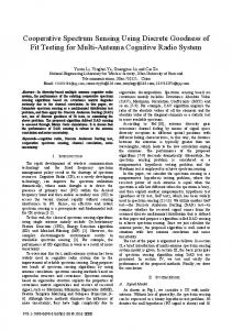
3) Comparison of the adaptive sensing range with the fixed sensing range: We assume that the cooperative partners are distributed uniformly in the transmission range of SU transmitter and all PU transmitters are distributed uniformly over the whole area. In Fig.3, if the cooperative partners sense outside the area of Rs , this area is called the unnecessary sensed area. If the cooperative partners do not sense inside the area of Rs , this area is called the unsensed area. Both areas are related to the degradation. If it is possible, the cooperative partners do not generate these areas to detect the maximum available channels. We consider the representative cases of two and three cooperative partners with the assumption that the cooperative partners are uniformly distributed in the transmission range of SU transmitter. In addition, if the fixed sensing range is smaller than Rs , then the fixed sensing range scheme is worse than the adaptive sensing range scheme as the cooperative partners are closer to node A. Thus, we will only consider the fixed sensing range of the cooperative partners is equal to Rs as in Fig.3. For simplicity, we assume Rs is 2.78 ∗ Rt for a two-ray ground reflection model (α is equal to 4) when √ the capture threshold (S0 ) is 10dB from Eq.(6) (e.g., (1 + 4 10) × dt = 2.78 × dt ). First, we explain the cooperative sensing with the fixed sensing range. Then, we explain the cooperative sensing with the adaptive sensing range. Fig.5 and Fig.6 show the result of the former cases. Fig.7 and Fig.8 are for the latter cases. Finally, we compare the performances of schemes using the fixed sensing range and the adaptive sensing range. To compare the performance of both cases, we calculate the white area which represents the sensed area by the cooperative partners and the gray area which includes the unnecessary sensed area
) (7)
√ where k = α Gt Gr h2t h2r Pt is a constant and d is the distance between the cooperative partner and the requesting node A. Since SU transmitter’s sensing range has been known from Eq.(6), we can easily get the cooperative partner’s sensing range (CPSR) to detect node C as follows, 4
S
(S) and/or the unsensed area (S’) from Fig.5 through Fig.8. Then, we calculate the ratio of them. Let ρ denote the ratio of gray part to the white part. Thus, the smaller ρ represents the better performance. If we substitute 1 for Rt , then R is equal to R = 2.78 ∗ Rt = 2.78. Here R is the sensing range and Rt is the transmission range of node A. In Fig.5, the gray and white areas can be calculated as follows, GrayArea = 2 × S + 2 × S ′ ( ( )) ) ( Rt Rt 2 −1 2 −1 = 4R sin 2 sin + 8R sin 2R 2R ( ( )) ( ) Rt Rt −R2 sin2 sin−1 − 2R2 sin−1 R R
d
W hiteArea = πR − 2S 2
B
R t/2 A
Rt
D
C
R
3 Rt 2
d =
Fig. 6. Cooperative sensing using three partners with the fixed sensing range
′
Then, ρ is given by ρ=
GrayArea 5.57511693349 = = 0.22983667823 W hiteArea 24.2568646087
WA = Last term of Gray Area
(10)
Then, ρ is given by
R’
ρ=
GrayArea 3.42504741934 = = 0.164235907167 W hiteArea 20.8544372447
(12)
S’
S
R
Rt/2 B
R A
C
Rt/2
(R-Rt/2) B
A
C
Fig. 5. Cooperative sensing using two partners with the fixed sensing range
In Fig.6, there is no unsensed area but only unnecessary sensed area. The gray and white areas can be calculated as follows [13], { ( ( √ )) ( √ )} 3Rt 3Rt GA = 3R2 sin 2 sin−1 4R + 2sin−1 4R {√ } ( C ) C√ + 43 C 2 + 3R2 sin−1 2R − 4 4R2 − C 2 − πR2 √ √ √ √ 2 2 3Rt t) t) where C 2 = 3R2 − ( 3R − 3R2 − 3 ( 3R 8 2 16 W A = πR2
Fig. 7. range
In Fig.8, there is no unnecessary sensed area but only unsensed area. The gray and white areas can be calculated as ′ GA = 3 × ( √ ( )) )2 (S Rt 3Rt −1 2 ( ) = πR − 3 R − {sin 2 sin 2 4 R − R2t ( √ ) √ ( )2 Rt 3Rt 3 2 −1 ( ) }−{ + 2sin C + 3{ R − 4 2 4 R − R2t √ ( ) ( )2 C Rt C ( ) − 4 R− − C 2 }} sin−1 Rt 4 2 2 R− 2 √ 2R − Rt 2 ( 3Rt )2 2 where C = 3( ) − 2 8 √ √ √ 2R − Rt 2 ( 3Rt )2 3Rt − 3( ) −3 2 2 16
Then, ρ is given by ρ=
7.5180991866 GrayArea = = 0.309648219089 W hiteArea 24.279484664
Cooperative sensing using three partners with the adaptive sensing
(11)
In Fig.7, there is no unnecessary sensed area but only unsensed area. The gray and white areas can be calculated as follows, )2 ( )2 ( 2R − Rt 2R − Rt − {π GA = πR2 − {2π 2 2 ( )2 )) ( ( 2R − Rt Rt −1 − sin2 sin 2 2R − Rt )2 ( ) ( R 2R − Rt t −1 }} −2 sin 2 2R − Rt 5
TABLE I S UMMARY OF THE COMPARISON OF USING THE ADAPTIVE SENSING RANGE AGAINST THE FIXED SENSING RANGE . (*CP: C OOPERATIVE PARTNER ) CASE
ρ
# of CP*
Distance A to CP*
Fixed
0.466660365253
2
Rt
Adaptive
0.455675799872
2
Rt
Fixed(Fig.5)
0.229836667823
2
Rt \ 2
Adaptive(Fig.7)
0.164235907167
2
Rt \ 2
Fixed
0.638694655838
3
Rt
Adaptive
0.206559004696
3
Rt
Fixed(Fig.6)
0.309648219089
3
Rt \ 2
Adaptive(Fig.8)
0.076990528614
3
Rt \ 2
transmitter and receiver problems in ad-hoc networks and shown that the cooperative spectrum sensing with adaptive sensing ranges is better than that with a fixed sensing range. Cooperative sensing using our proposed adaptive sensing range is very effective in solving the hidden receiver problem. Multi-channel MAC protocols have advantages such as the reduced interference among the nodes and the increased capacity of wireless networks significantly by simultaneously operating over multiple channels even if each node only occupies one channel at a time. In future, we will investigate and design an effective cognitive multi-channel MAC protocol combined with cooperative sensing using adaptive sensing ranges proposed in this paper. R EFERENCES [1] Federal Communication Commission, ”Spectrum policy task force report, FCC -2-155.” Nov. 2002. [2] FCC, ”Et docket no. 03-237,” Nov. 2003. U RL : http : //hraunf oss.f cc.gov/edocp ublic/attachmatch/F CC− 03 − 289A1.pdf [3] W. Ren, Q. Zho, and A. Swami, ”Power Control in Cognitive Radio Netwroks: How to Cross a Multi-Lane Highway,” IEEE Journal on Selected Area in Communications (JSAC): Special Issue on Stochastic Geometry and Random Graphs for Wireless Netwroks, Aug. 2008. [4] K. Xu, M. Gerla, and S. Bae, ”How effective is the IEEE 802.11 RTS/CTS Handshake in Ad Hoc Networks?” IEEE Communications Society GLOBECOME, 2002. [5] I.F. Akyildiz, W.-Y. Lee, M.C. Vuran, and M.Shantidev, ”NeXt Generation/dynamic spectrum access/cognitive radio wireless networks: a survey,” Computer Networks Journal 50 (2006), pp. 2127-2159. [6] T. Rappaport, ”Wireless Communications: Principles and Practive,” Prentice Hall, New Jersey, 2002. [7] P. Gupta and P.R. Kumar, ”The Capacity of Wireless Network,” IEEE Trans. on Information Theory, vol. 46, no.2, March 2000, pp.388-404. [8] F. Ye, S. Yi, and B. Sikdar, ”Improving Spatial Reuse of IEEE 802.11 Mesh Networks with Enhanced Physical Carrier Sensing,” IEEE Communicaitions Society GLOBECOM, 2003. [9] K. Xu, M. Gerla, and S. Bae, ”Effectiveness of RTS/CTS handshake in IEEE 802.11 based Ad Hoc Networks,” Ad Hoc Netwroks 1 (ELSEVIER), 2003, pp.107-123. [10] J. Zhu, X. Guo, L.L. Yang, and W.S. Conner, ”Leveraging Spatial Reuse in 802.11 Mesh Networks with Enhanced Physical Carrier sensing,” IEEE International Conference on Communications, vol.7, Jun. 2004, pp.40041011. [11] A. Ghasemi and E.S. Sousa, ”Opportunistic Spectrum Access in Fading Channels Through Coolaboratieve Sensing,” IEEE Journal of Communications, vol.2, no.2, 2007. [12] A. Ghasemi and E.S. Sousa, ”Collaborative Spectrum Sensing for Opportunistic Access in Fading Environments,” IEEE NFDSAN, 2005, pp.131-136. [13] M.P. Fewell, ”Area of Common Overlap of Three Circles,” Australian Government, Maritime Operations Division, Technical Note, Depart of Defence, Oct. 2006.
WA = Last term of Gray Area Then, ρ is given by ρ=
GrayArea 1.73566090795 = = 0.076990528614 W hiteArea 22.5438237561
(13)
S’
B
d R t/2
Rt
A
D
C
R
d =
Fig. 8. range
3 Rt 2
Cooperative sensing using three partners with the adapted sensing
From Eq.(10) to Eq.(13), the scheme with the adaptive sensing range has smaller ρ value than that with the fixed sensing range for two and three cooperative partners, respectively. Therefore, cooperative sensing using our proposed adaptive sensing range is very effective in solving the hidden receiver problem. Moreover, by increasing the number of cooperative partners, the cooperative sensing scheme is even capable of outperforming in AWGN channels (# of cooperative partner = 1) [11]. Table.1 summarizes the comparison of using the adaptive sensing range against the fixed sensing range. Due to the space limit, the theoretical analysis for four cases where the distance between node A and cooperative partners is Rt is omitted here. IV. C ONCLUSIONS Cognitive radio is an innovative technology to improve the utilization efficiency of the radio spectrum. Cooperative spectrum sensing plays a key role to increase greatly the probability of detection in a channel fading environment. In this paper, we have proposed the solutions for the hidden 6