Abstractâ COordinate Rotation DIgital Computer (CORDIC) ... architecture has taken place for achieving high throughput rate ... signal processing solutions.
(IJACSA) International Journal of Advanced Computer Science and Applications, Vol. 2, No. 4, 2011
Coordinate Rotation Digital Computer Algorithm: Design and Architectures Naveen Kumar
Amandeep Singh Sappal
Electronics & Communication Engineering University College of Engineering Punjabi University, Patiala Punjab, India
Electronics & Communication Engineering University College of Engineering Punjabi University, Patiala Punjab, India
Abstract— COordinate Rotation DIgital Computer (CORDIC) algorithm has potential for efficient and low-cost implementation of a large class of applications which include the generation of trigonometric, logarithmic and transcendental elementary functions, complex number multiplication, matrix inversion, solution of linear systems and general scientific computation. This paper presents a brief overview of the developments in the CORDIC algorithm and its architectures. Keywords- CORDIC Algorithms; CORDIC Architectures; FPGA.
I.
INTRODUCTION
FIRST described in 1959 [1], CORDIC algorithm is an iterative algorithm, which can be used for the computation of trigonometric functions, multiplication and division. Last half century has witnessed a lot of progress in design and development of architectures of the algorithm for highperformance and low-cost hardware solutions. CORDIC algorithm got its popularity, when [2] showed that, by varying a few simple parameters, it could be used as a single algorithm for unified implementation of a wide range of elementary transcendental functions involving logarithms, exponentials, and square. During the same time, [3] showed that CORDIC technique is a better choice for scientific calculator applications. The popularity of CORDIC was very much enhanced thereafter primarily due to its potential for efficient and lowcost implementation. With the advent of low cost, low power FPGAs, this algorithm has shown its potential for efficient and low-cost implementation. CORDIC algorithm can be widely used in as wireless communications, Software Defined Radio and medical imaging applications, which are heavily dependent on signal processing. Some other upcoming applications are:
Direct frequency synthesis, digital modulation and coding for speech/music synthesis and communication; Direct and inverse kinematics computation for robot manipulation; Planar and three-dimensional vector rotation for graphics and animation. Although CORDIC may not be the fastest technique to perform these operations, yet it is attractive due to the simplicity and efficient hardware implementation.
The development of CORDIC algorithm and architecture has taken place for achieving high throughput rate and reduction of hardware-complexity as well as the latency of implementation. Latency of implementation is an inherent drawback of the conventional CORDIC algorithm. Angle recoding schemes and higher radix CORDIC have been developed for reduced latency realization. Parallel and pipelined CORDIC have been suggested for high-throughput computation. This paper presents an overview of the development of CORDIC algorithm. The paper is organized as follows: Section II discusses the basics of CORDIC algorithm, different CORDIC architectures are discussed in Section III. The conclusion along with future research directions are discussed in Section IV. II.
DEFINITION OF CORDIC
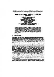
The CORDIC is very simple and iterative convergence algorithm that reduces complex multiplication, greatly simplifying overall hardware complexity. This serves as an attractive option to system designers as they continue to face the challenges of balancing aggressive cost and power targets with the increased performance required in next generation signal processing solutions. The basic principle underlying the CORDIC-based computation, and present its iterative algorithm for different operating modes and planar coordinate system. A. Overview of CORDIC Algorithm CORDIC algorithm has two types of computing modes Vector rotation and vector translation. The CORDIC algorithm was initially designed to perform a vector rotation, where the vector V with components (X,Y) is rotated through the angle yielding a new vector V ' with component (X’,Y’) shown in Fig. 1.
V ' [ R][V ]
(1)
where R is the rotation matrix:
68 | P a g e http://ijacsa.thesai.org/
(IJACSA) International Journal of Advanced Computer Science and Applications, Vol. 2, No. 4, 2011
To achieve simplicity of hardware realization of the rotation, the key ideas used in CORDIC arithmetic are to decompose the rotations into a sequence of elementary rotations through predefined angles that could be implemented with minimum hardware cost and to avoid scaling, that might involve arithmetic operation, such as square-root and division. The second idea is based on the fact the scale-factor contains only the magnitude information but no information about the angle of rotation. Figure 1: Vector Rotation
cos R sin
sin cos
1 tan 2 1 tan 1 tan 2 R tan 1 2 1 tan 2 1 tan By factoring out the cosine term R can be rewritten as
R 1 tan 2
1/2
(2)
(3) in (3), the rotation matrix
1 tan tan 1
B. Generalized CORDIC Algorithm After few years, Walther found how CORDIC iterations could be modified to compute hyperbolic functions [2] and reformulated the CORDIC algorithm in to a generalized and unified form which is suitable to perform rotations in circular, hyperbolic and linear coordinate systems. The unified formulation includes a new variable m , which is assigned different values for different coordinate systems. The generalized CORDIC is formulated as follows:
xi 1 xi m i .2 i. yi yi 1 yi i .2 i.xi wi 1 wi i . i
(4)
and can be interpreted as a product of a scale-factor
1/2 K 1 tan 2 with a pseudo rotation matrix Rc ,
Here
tan 1
(5)
In vector translation, rotates the vector V with component (X, Y) around the circle until the Y component equals zero as illustrated in Fig. 2. The outputs from vector translation are the ' magnitude X’ and phase , of the input vector V. After vector translation, output equations are:
X' = K i
X
2
Y2
Y 0 '
(6) (7)
Y X
' a tan
Figure 2: Vector Translation
(8)
sign( wi ) for rotation mode sign( wi ) for vectoring mode
i
III.
given by
1 Rc tan
(9)
CORDIC ARCHITECTURES
CORDIC computation is inherently sequential due to two main bottlenecks firstly the micro-rotation for any iteration is performed on the intermediate vector computed by the previous iteration and secondly the (i+1)th iteration could be started only after the completion of the ith iteration, since the value of i 1 which is required to start the (i+1)th iteration could be known only after the completion of the ith iteration. To alleviate the second bottleneck some attempts have been made for evaluation of i values corresponding to small micro-rotation angles [4]. However, the CORDIC iterations could not still be performed in parallel due to the first bottleneck. A partial parallelization has been realized in [4] by combining a pair of conventional CORDIC iterations into a single merged iteration which provides better area-delay efficiency. But the accuracy is slightly affected by such merging and cannot be extended to a higher number of conventional CORDIC iterations since the induced error becomes unacceptable [5]. Parallel realization of CORDIC iterations to handle the first bottleneck by direct unfolding of micro-rotation is possible, but that would result in increase in computational complexity and the advantage of simplicity of CORDIC algorithm gets degraded [6]. Although no popular architectures are known to us for fully parallel implementation of CORDIC, different forms of pipelined implementation of CORDIC have however been proposed for improving the computational throughput [7].To handle latency bottlenecks, various architectures have been developed and reported in this review. Most of the well-known architectures could be grouped under bit parallel iterative CORDIC, bit parallel unrolled CORDIC , bit serial iterative CORDIC and
69 | P a g e http://ijacsa.thesai.org/
(IJACSA) International Journal of Advanced Computer Science and Applications, Vol. 2, No. 4, 2011
pipelined CORDIC architecture which we discuss briefly in the following subsections.
B. Bit Parallel Unrolled CORDIC Architecture
A. Bit Parallel Iterative CORDIC Architecture The vector Rotation CORDIC structure is represented by the schematics in Fig. 3. Each branch consists of an addersubtractor combination, a shift unit and a register for buffering the output. At the beginning of a calculation initial values are fed into the register by the multiplexer where the MSB of the stored value in the z-branch determines the operation mode for the adder-subtractor. Signals in the x and y branch pass the shift units and are then added to or subtracted from the unshifted signal in the opposite path. The z branch arithmetically combines the registers values with the values taken from a lookup table (LUT) whose address is changed accordingly to the number of iteration. For n iterations the output is mapped back to the registers before initial values are fed in again and the final sine value can be accessed at the output. A simple finite-state machine is needed to control the multiplexers, the shift distance and the addressing of the constant values. When implemented in an FPGA the initial values for the vector coordinates as well as the constant values in the LUT can be hardwired in a word wide manner. The adder and the subtractor component are carried out separately and a multiplexer controlled by the sign of the angle accumulator distinguishes between addition and subtraction by routing the signals as required. The shift operations as implemented change the shift distance with the number of iterations but those require a high fan in and reduce the maximum speed for the application. In addition the output rate is also limited by the fact that operations are performed iteratively and therefore the maximum output rate equals 1/n times the clock rate.
Figure 3: Iterative CORDIC
Figure 4: Unrolled CORDIC
Instead of buffering the output of one iteration and using the same resources again, one could simply cascade the iterative CORDIC, which means rebuilding the basic CORDIC structure for each iteration. Consequently, the output of one stage is the input of the next one, as shown in Fig. 4, and in the face of separate stages two simplifications become possible. First, the shift operations for each step can be performed by wiring the connections between stages appropriately. Second, there is no need for changing constant values and those can therefore be hardwired as well. The purely unrolled design only consists of combinatorial components and computes one sine value per clock cycle. Input values find their path through the architecture on their own and do not need to be controlled. As we know, the area in FPGAs can be measured in CLBs, each of which consist of two lookup tables as well as storage cells with additional control components. For the purely combinatorial design the CLB's function generators perform the add and shift operations and no storage cells are used. This means registers could be inserted easily without significantly increasing the area. Pipelining ads some latency, of course, but the application needs to output values at 48 kHz and the latency for 14 iterations equals 312.5 s which are known to be imperceptible. However, inserting registers between stages would also reduce the maximum path delays and correspondingly a higher maximum speed can be achieved. C. Bit Serial Iterative CORDIC Architecture Both, the unrolled and the iterative bit-parallel designs, show disadvantages in terms of complexity and path delays
70 | P a g e http://ijacsa.thesai.org/
(IJACSA) International Journal of Advanced Computer Science and Applications, Vol. 2, No. 4, 2011
going along with the large number of cross connections between single stages. To reduce this complexity one could change the design into a completely bit-serial iterative architecture. Bit-serial means only one bit is processed at a time and hence the cross connections become one bit-wide data paths. Clearly, the throughput becomes a function of In spite of this the output rate can be almost as high as achieved with the unrolled design. The reason is the structural simplicity of a bitserial design and the correspondingly high clock rate achievable. Fig. 5 shows the basic architecture of the bit serial CORDIC processor.
clock rate number of iterations word length
Figure 5: Bit-serial CORDIC
D. D. Pipelined CORDIC Architecture Since the CORDIC iterations are identical, it is very much convenient to map them into pipelined architectures. The main emphasis in efficient pipelined implementation lies with the minimization of the critical path. The earliest pipelined architecture that we find was suggested in 1984. Pipelined CORDIC circuits have been used thereafter for highthroughput implementation of sinusoidal wave generation, fixed and adaptive filters, discrete orthogonal transforms and other signal processing applications [8]. IV.
CONCLUSION
CORDIC algorithm can be implemented by using simple
hardware through repeated shift-add operations. This feature makes it attractive for a wide variety of applications. Moreover, its applications in several diverse areas including signal processing, image processing, communication, robotics and graphics apart from general scientific and technical computations have been explored. In the last half century, several algorithms and architectures have been developed to speed up the CORDIC algorithm by reducing its iteration counts and through its pipelined implementation. ACKNOWLEDGMENT The authors would thanks the reviewers for their help in improving the document. REFERENCES [1] J. E. Volder, “The CORDIC trigonometric computing technique,” IRE Transactions on Electronic Computers, vol. EC- 8, pp. 330–334, Sept. 1959. [2] J. S. Walther, “A unified algorithm for elementary functions,” in Proceedings of the 38th Spring Joint Computer Conference, Atlantic City, NJ, 1971, pp.379–385. [3] D. S. Cochran, “Algorithms and accuracy in the HP-35,” Hewlett-Packard Journal, pp. 1–11, June 1972. [4] S. Wang, V. Piuri, and J. E. E. Swartzlander, “Hybrid CORDIC algorithms,”IEEE Transactions on Computers, volume 46, no. 11, pp. 1202–1207, November1997. [5]S. Wang and E. E. Swartzlander, “Merged CORDIC algorithm,” in IEEE International Symposium on Circuits Systems (ISCAS’95),1995, volume 3, pp.1988–1991. [6] B. Gisuthan and T. Srikanthan, “Pipelining flat CORDIC based trigonometric function generators,” Microelectronics Journal, volume 33, Pp.77–89, 2002. [7] E. Deprettere, P. Dewilde, and R. Udo, “Pipelined CORDIC architectures for fast VLSI filtering and array processing,” in IEEE International Conference on Acoustic, Speech, Signal Processing, ICASSP’84, March 1984, volume 9, pp.250–253. [8] D. E. Metafas and C. E. Goutis, “A floating point pipeline CORDIC processor with extended operation set,” in IEEE International Symposium on Circuits and Systems, ISCAS’91, June 1991, volume 5, pp. 3066–3069. AUTHORS PROFILE Naveen Kumar received the Bachelor of Technology (B.TECH) degree in 2009. Currently he is pursuing Master of Technology (M.Tech) in Electronics & Communication from Punjabi University Patiala, India. Amandeep Singh Sappal has submitted his Ph.D. in Electronics & Communication at Punjabi University Patiala and presently he is working as an Assistant Professor in Punjabi University Patiala, India. He has published more than 25 papers in reputed journals and conferences. He is reviewer of prestigious journals like Elsevier and Springer etc. Presently he is guiding 5 M.tech students.
71 | P a g e http://ijacsa.thesai.org/