(b) Desk. (c) Electrical Cabinet. (d) Racing Car. Figure 2. The four different scenes, which are contained in our CoRBS. The top row shows raw color images, ...
CoRBS: Comprehensive RGB-D Benchmark for SLAM using Kinect v2 Oliver Wasenm¨uller Marcel Meyer Didier Stricker DFKI - German Research Center for Artificial Intelligence, Kaiserslautern, Germany {oliver.wasenmueller, marcel.meyer, didier.stricker}@dfki.de
Abstract In scientific evaluation public datasets and benchmarks are indispensable to perform objective assessment. In this paper we present a new Comprehensive RGB-D Benchmark for SLAM (CoRBS). In contrast to state-of-the-art RGB-D SLAM benchmarks, we provide the combination of real depth and color data together with a ground truth trajectory of the camera and a ground truth 3D model of the scene. Our novel benchmark allows for the first time to independently evaluate the localization as well as the mapping part of RGB-D SLAM systems with real data. We obtained the ground truth for the trajectory using an external motion capture system and for the scene geometry via an external 3D scanner, each with sub-millimeter precision. With precise calibration and systematic validation we ensured the high quality of CoRBS. Our dataset contains twenty image sequences of four different scenes captured with a Kinect v2. We provide all data in a global coordinate system to enable direct evaluation without any further alignment or calibration.
1. Introduction Public benchmarks have a long and convincing history in the Computer Vision community. In the literature several examples exist, which considerably pushed forward the state-of-the-art [5, 11, 25, 27, 32]. A major problem in Computer Vision and Robotics is the so-called Simultaneous Localization And Mapping (SLAM) [9], where the goal is to simultaneously estimate the camera trajectory and a map of the environment. RGB-D sensors are often used in this context [13, 20, 23, 31], because they provide both color and depth images, are low-cost and widely spread. Recently several algorithms have been developed and evaluated using the Microsoft Kinect v1, since it was one of the most common RGB-D devices, but suffering from a high noise level [18]. With the release of the Microsoft Kinect v2 [22] a new promising device is available, which claims much better quality and will – most probably – be the basis for the development and evaluation in many future research. Our contribution in this paper is a Comprehensive RGB-D Benchmark for SLAM (CoRBS). Compared to
(a) Microsoft Kinect v2
(b) Ground Truth 3D Scanner
(c) Ground Truth Motion Capture
(d) Exemplary Map Evaluation
Figure 1. We present our CoRBS benchmark, which uses (a) the Microsoft Kinect v2 and provides ground truth (b) for the 3D geometry of the scene as well as (c) for the camera trajectory in order to (d) evaluate all parts of SLAM algorithms separately.
state-of-the-art RGB-D SLAM benchmarks [12, 21, 29, 33], our CoRBS is the first providing the combination of real depth and color data together with a ground truth trajectory of the camera and a ground truth 3D model of the scene. Thus, our benchmark covers the localization as well as the mapping part of SLAM systems and can be used to independently evaluate both aspects with real data. To generate a precise ground truth of the camera trajectory, we affixed reflective markers on the camera (Figure 1a), which are tracked by an active external motion tracking system. The ground truth of the scene geometry is acquired with a precise external 3D scanner using structured light. CoRBS is the first SLAM benchmark using the Microsoft Kinect v2 as an input device. Furthermore, we are providing all data in a global coordinate system so that no further alignment or calibration is necessary for evaluation with our benchmark. CoRBS consists in total of twenty sequences of four different scenes. It is available under the Creative Commons 3.0 Attribution License at http://corbs.dfki.uni-kl.de
Benchmark Meister [21] Sturm [29] Zhou [33] Handa [12] CoRBS (our)
Device Kinect v1 Kinect v1 Xtion Pro synthetic Kinect v2
Camera Trajectory no ground truth computed synthetic ground truth
Scene Geometry ground truth no computed synthetic ground truth
Global Coordinate System no no no no yes
Number of Trajectories 3 39 8 8 20
Number of Scenes 3 8 2 4
Table 1. Comparison of state-of-the-art RGB-D benchmarks. Our CoRBS is the only one providing real image data together with a ground truth trajectory of the camera and a ground truth 3D model of the scene. All data is in a global coordinate system, so that benchmarking can directly be applied.
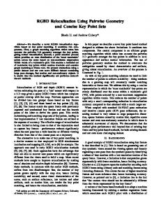
(a) Human
(b) Desk
(c) Electrical Cabinet
(d) Racing Car
Figure 2. The four different scenes, which are contained in our CoRBS. The top row shows raw color images, whereas the middle row shows color-coded depth images recorded by the Kinect v2. The bottom row illustrates the ground truth reconstructions of the corresponding scene. Exemplary camera trajectories are depicted in Figure 3.
2. Related Work SLAM algorithms with different capturing devices were investigated and evaluated in the Computer Vision and Robotics community for several years. Besides benchmarks focusing on standard cameras [2, 5, 11, 19], also some benchmarks explicitly using RGB-D cameras exist as listed in Table 1. Meister et al. [21] published recordings of three different scenes using the Kinect v1 together with laser scans of the scenes. Since they do not provide any information about the camera position, this dataset can only be used for the evaluation of a complete SLAM algorithm. Sturm et al. [29] provide a large benchmark with in total 39 camera trajectories using the Kinect v1. They measured the camera position very precisely with an external
active motion capturing system, but do not provide any information about the scene geometry. Thus, their benchmark is well suited for the evaluation of the localization part of SLAM, but not for the mapping part. Zhou et al. [33] released a dataset with eight scenes and one camera trajectory per scene using the Asus Xtion Pro. The provided camera positions were estimated with an odometry algorithm and the scene geometry is the output of their algorithm. Consequently, their data are only approximations and can not be used as a ground truth. Handa et al. [12] proposed a benchmark with synthetic data. They created two virtual scenes, rendered color and depth images including a noise model along a camera trajectory and exported the scene geometry. In general, this benchmark can be used to evaluate both parts of SLAM in-
(a) D5
(b) E5
(c) H4
Figure 3. Three exemplary camera trajectories showing the diversity of the trajectories contained in CoRBS.
dividually. However, the significance of the derived conclusions is limited, since real world data is missing. Furthermore, a global calibration is missing, meaning that camera trajectory and scene model are in a different coordinate system. Summarized, all existing benchmarks have specific drawbacks. Synthetic or computed data are only of limited significance, because conclusions to the real world are difficult. None of the benchmarks can be used to comprehensively benchmark a SLAM algorithm, since they either provide ground truth for the camera trajectory or for the scene geometry, but not for both. Thus, recent publications for RGB-D SLAM [6, 10, 15, 16] struggle with evaluating and comparing their results, especially the mapping part.
3. Dataset We use for our dataset the Microsoft Kinect v2 [22], which is an RGB-D camera consisting of one Time-ofFlight (ToF) and one color camera. The ToF camera captures two kinds of images: depth image and infrared image. The depth image records in each pixel the distance from the camera to a seen object by estimating the time emitted light takes from the camera to the object and back. The infrared image indicates the intensity of the received light. We refer to this ToF camera in the following as depth camera. Infrared images were only rarely used in the past, except in the context of color estimation [17]. However, we provide them for the sake of completeness and hope to support future research. Our CoRBS benchmark is composed of twenty image sequences of four different scenes, namely Human, Desk, Electrical Cabinet and Racing Car. An overview of the four scenes is provided in Figure 2. The Human is a simple wooden manikin whose surface is predominantly convex, but also contains fine details, e.g. at the hands. The Desk scene incorporates more complex geometry and includes a slightly reflective screen. The most challenging geometry offers the Electrical Cabinet scene with its delicate geometry in the interior and flat surfaces on the exterior. The Racing Car includes many straight and weakly bended ar-
Name
Duration [s]
Human H1 51.1 H2 86.8 42.9 H3 H4 239.2 H5 60.5 Desk D1 23.4 D2 81.3 59.8 D3 D4 65.7 D5 39.2 Electrical Cabinet E1 27.0 E2 66.7 E3 165.3 E4 43.6 E5 76.3 Racing Car R1 93.4 R2 127.6 R3 85.0 R4 37.1 R5 104.0
Length [m]
Avg. Trans. Vel. [m/s]
Avg. Rot. Vel. [deg/s]
11.3 15.4 13.5 59.3 26.0
0.222 0.177 0.315 0.247 0.429
19.02 23.15 29.81 22.97 39.42
5.4 11.5 23.3 13.3 16.4
0.231 0.141 0.390 0.202 0.419
34.08 23.96 56.52 21.88 33.73
11.3 23.0 47.0 7.7 12.9
0.420 0.344 0.284 0.178 0.169
38.60 26.33 27.92 21.40 22.13
21.0 34.1 20.2 21.6 28.4
0.225 0.267 0.238 0.584 0.273
25.83 31.10 16.93 62.78 45.01
Table 2. List of RGB-D sequences in our benchmark.
eas, while incorporating the challenge of a sightly reflective carbon surface. Each single dataset consists of the color, depth and infrared images of the Kinect, a ground truth camera trajectory and a ground truth model of the scene. The ground truth camera trajectory is acquired with a precise external motion capture system and the ground truth model of the scene is reconstructed with a precise external structured light system. Exemplary ground truth camera trajectories are depicted in Figure 3, whereas Figure 2 shows in the bottom row the ground truth 3D models of the scenes. For each scene we tried to capture trajectories with
color depth infrared
X Resolution [Pixel] 1920 512 512
Y Resolution [Pixel] 1080 424 424
Frame Rate [Hz] 30 30 30
Table 3. Resolution and frame rate of the images captured by a Microsoft Kinect v2.
different characteristics. This incorporates loop closures, twisting, slow vs. fast movement, short vs. large distance, etc. A detailed description of each dataset can be found on our website [8], whereas Table 2 summarizes some statistics over our datasets. Besides the above mentioned datasets, we also provide a set of images for calibration. Therefore, we captured a 9 × 7 checkerboard with 40 mm square size with a handheld Kinect and provide the corresponding color, depth and infrared images.
4. Data Acquisition
Figure 4. Schematic overview of our capturing process. Our RGB-D camera is the Microsoft Kinect v2 (black) capturing color, depth and infrared images. The camera position is estimated with an external motion tracking system (red), which is tracking reflective markers on the Kinect v2. The scene geometry is reconstructed with a precise external 3D scanner (blue) using structured light. Note, the proportions in this schematic overview are not correct, but this increases clarity considerably.
4.1. Kinect We recorded all images with a Microsoft Kinect v2 in the raw output conditions using the official SDK (version 2.0). This means we recorded the images with the resolutions of Table 3. Note, the observed raw images are not yet registered (cp. Section 5.1), as the color and depth camera are located on two different positions. Since the Kinect is heating up during capturing, we were running the camera for at least 30 min before each recording to prevent any influence of temperature. Furthermore, we performed all recordings in an air-conditioned room with constant temperature.
4.2. Camera trajectory To provide a precise ground truth of the camera trajectory we used an external motion capture system of OptiTrack [24] (see Figure 1c), composed of twelve Flex 13 cameras with a resolution of 1280 × 1024 at 120 Hz. We estimated the camera positions with the Motive software (version 1.5.0) of the motion capture system by tracking passive spherical markers, which were rigidly attached to the Kinect as shown in Figure 1a. To detect the passive marker robustly and precisely, the motion capture cameras emit infrared light into our capture volume of approximately 6 × 6 meter. We verified that the infrared light of the Kinect and the motion capture system do not interfere.
4.3. Ground truth scene The precise ground truth for the geometry of the captured scene was reconstructed with an external 3D scanner of 3Digify [1]. This scanner acquires the 3D geometry by projecting a fringe pattern and captures the distortion of this pattern over the object surface with two 18 MP cameras (see
Figure 1b). The geometry is reconstructed at high quality using the triangulation principle. The accuracy depends on several circumstances such as surface material, angle of view, etc. For our reconstructions we achieved an average accuracy of 0.2 mm.
5. Calibration For our CoRBS benchmark we were using three independent systems: the Kinect v2, the motion capture system and the 3D scanner. To enable a direct evaluation with our benchmark, all these systems must be calibrated together in a single global coordinate system.
5.1. Kinect Calibration The used Kinect needs to be calibrated in oder to describe its properties mathematically and to register depth and color image. In the literature, several approaches for the calibration of RGB-D cameras exist [3, 14, 28] , while we used the toolbox of Bouguet [4]. Therefore, we first performed a separate intrinsic calibration for the color and depth camera by using color and infrared images. As a result we obtained the focal lengths (fx ,fy ) and the camera centers (cx , cy ) for both cameras. We decided to estimate distortion coefficients r1 , r2 , r3 , t1 , t2 for the color camera only, since undistortion of depth images is not trivial. However, one can compute and apply his own undistortion with the provided data. In a next step, we conducted an extrinsic
camera fx fy cx cy color 1054.35 1054.51 956.12 548.99 depth 363.58 363.53 250.32 212.55 camera r1 r2 r3 t1 t2 color 0.050 -0.062 -0.002 -0.002 0.000 0.000 0.000 0.000 0.000 0.000 depth Table 4. Derived calibration parameters - focal length (fx ,fy ), camera center (cx , cy ), radial distortion coefficients r1 , r2 , r3 and tangential distortion coefficients t1 , t2 - for the used Kinect v2.
calibration of the two cameras resulting in the homography 1.0000 0.0084 −0.0054 −52.05 0.0084 −1.0000 0.0009 −0.46 (1) Hd2c = −0.0054 −0.0009 −1.0000 0.89 0 0 0 1 which transfers the depth image into the coordinates of the color image. As a result, corresponding color and depth pixels coincide. This is an optimization problem in which extrinsic and intrinsic parameters are estimated together [4]. The final intrinsic parameters for the used Kinect v2 are depicted in Table 4.
5.2. Motion Capture System Calibration We calibrated our motion capture system using the offthe-shelf Motive software of OptiTrack [24]. The system is calibrated by waving a calibration wand with three markers of fixed distance. Based on the captured correspondences, the software computes the poses and intrinsics of the motion capture system cameras automatically. The system is then able to provide the position and rotation of a rigid collection of at least three markers with an update rate of 120 Hz. As visible in Figure 1a, we attached to our Kinect v2 six markers on boundary points of the camera case to enable robust estimations. The calibration software determined a mean 3D error of 0.39 mm for the rigid marker collection on the camera in our setup.
5.3. Time Synchronization Since the Kinect and the motion capture system are two independent systems, the data of corresponding camera pose and image frame do not arrive exactly at the same time on our recording computer. Thus, a synchronization between the two systems is essential. To detect corresponding camera pose and image frame we captured data of the Kinect, while standing still on a tripod first. Then, we moved the camera by a fast impulsive push. This push can easily be detected in the camera images as well as the pose data. We repeated this procedure at least six times for each dataset. With this approach we detected a mean error of 8.77 ms in the synchronization. Note that the motion tracking system (120 Hz) has a much higher sampling rate than
the Kinect (30 Hz), which obligatorily leads to errors in this range. We corrected already all files with the determined time delay.
5.4. Hand Eye Calibration The motion capture system (cp. Section 4.2) tracks only the pose of the rigid collection of the attached reflective markers. To use the images of the benchmark, the pose of the color camera center is required, which is not necessarily the pose of the reflective marker collection. Nonetheless there exists a rigid transformation between these two poses that can be estimated with a so-called hand eye calibration [26, 30]. Here, we followed the approach of Tsai and Lenz [30] and captured a fixed pattern (in our case a checkerboard) from n perspectives, while recording the color images C1:n and the detected pose Hw2m,1:n of the marker collection in world coordinates. The camera poses Hc2p,1:n with respect to the pattern can be easily determined with [4] from the images C1:n . Since the position Hw2p of the pattern is fixed, one can build the equation system Hc2p,1:n ∗ Hm2c ∗ Hw2m,1:n = Hw2p
(2)
for all n perspectives and solve it for the wanted transformation Hm2c . In our experiments we captured n > 20 images to achieve robust results. We modified all provided camera trajectories with the estimated transformation Hm2c .
5.5. 3D Scan Alignment The scans of our 3D scanner (cp. Section 4.3) are upto-scale and in an independent coordinate system. Thus, a metrically correct scaling and an alignment with the coordinate system of the motion capture system is required to enable an easy and direct evaluation. Therefore, we placed in each scene in the outer boundaries n reflective markers of the motion capture system with the global coordinates p1:n . These positions can also be detected in the resulting mesh with local coordinates q1:n . First, we determined the scale by computing (n−1)! possible distances among all p1:n and compared them with the corresponding distances among all q1:n . The difference is a constant factor s, which is the scaling factor. Second, we estimated the rigid transformation Halign defined by Halign ∗ (q1:n · s) = p1:n
(3)
with a singular value decomposition (SVD) where at least three markers are necessary. For our experiments we placed n ≥ 4 markers in the scene in order to get more robust estimates. In our CoRBS we obtained a mean error of 0.89 mm for the scale and a mean 3D error of 0.98 mm for the alignment. Note, both errors include already all errors introduced by the 3D scanner and the motion capture system, whereas the alignment error additionally contains the scale error. We
applied the estimated transformations already on the provided data, so that all data are in one single global coordinate system. This means no further processing like aligning or calibrating is necessary for evaluation.
the trajectory over a fixed time interval ∆ and is defined at a time step i as �−1 −1 � RP Ei,∆ = A−1 Bi Bi+∆ . (4) i Ai+∆
5.6. Accuracy Analysis
To have meaningful error measures for the evaluation of a complete trajectory, we recommend to average over all possible time steps i and time intervals ∆ by v n u u 1 n−∆ X X 1 t ktrans(RP Ei,∆ )k2 , (5) n n − ∆ i=1
We determined the camera pose using an external motion capture system with an accuracy of 0.39 mm in position and 0.15 deg in rotation. For benchmarking the camera trajectory an absolute sub-millimeter and sub-degree accuracy is high enough to evaluate recent state-of-the-art approaches [12, 29], while future approaches can be evaluated as long as they have errors significantly above these values. The scene geometry is reconstructed using an external 3D scanner with an accuracy of 0.2 mm. The alignment to the global coordinate system has an accuracy below 1 mm. Thus, for benchmarking the map this accuracy is sufficient as long as errors in the map are significantly above 1 mm. While the above mentioned accuracies hold for the independent evaluation of trajectory and map, the errors accumulate if the provided trajectories are used for the map creation. For instance, the error in rotation propagates from 0.15 deg to an error of 2.6 mm in position for points in 1 m distance.
6. File Formats We decided to provide our image and pose data in the same format as Sturm et al. [29], because it has been used in many publications in the past. With this decision we hope to reduce the effort for using CoRBS significantly. A detailed description of the data formats can be found in [29]. Since the color and depth images are not registered a priori (cp. Section 5.1), we decided to provide two kinds of image sequence per dataset. The first kind are the original unregistered full resolution depth (512 × 424) and color (1920 × 1080) images. With these images one can apply an own calibration. The second kind are registered depth and color images, where we applied the transformation of Equation 1. In order to make the images easy applicable in many existing implementations, we provide both the color and the depth in a resolution of 640 × 480. Additionally, we provide for each scene a precise mesh (cp. Section 4.3) in the OBJ format including normal and texture map.
7. Evaluation Metrics The result of a SLAM algorithm is the estimated camera trajectory together with a map of the scene. CoRBS offers the opportunity to evaluate both outputs independently. For the evaluation of the camera trajectory we follow [29] and recommend the Relative Pose Error (RPE). Given is a sequence of poses from the estimated trajectory B1:n ∈ SE(3) and from the ground truth trajectory A1:n ∈ SE(3). The RPE measures the local accuracy of
∆=1
where trans(RP Ei,∆ ) refers to the translational components of the RPE. This metric can be applied, because we provide dense and absolute ground truth trajectories. Tools for evaluation and more details are provided in [29]. For the evaluation of the map we follow [12]. For each point Ei in the estimated map the closest triangle Fj in the reference mesh of the scene is located and the perpendicular distance between Ei and Fj is computed. In order to have meaningful error measures for the complete map, we recommend standard statistics like mean, median and standard deviation. Tools for this comparison are provided in CloudCompare [7]. Note that, compared to [12, 21], no alignment is necessary for evaluation, since we provide all data in a global coordinate system (cp. Section 5.5). An exemplary evaluation is depicted in Figure 1d, where we benchmarked the map of KinectFusion [23].
8. Conclusion In this paper we presented a new Comprehensive RGB-D Benchmark for SLAM (CoRBS). Besides color, depth and infrared images it also provides a ground truth for both the camera trajectory and the scene geometry. Since all data are provided in a global coordinate system, one can directly evaluate all parts of SLAM algorithms without any additional calibration or alignment. With precise calibration and systematic validation we ensured the high quality of CoRBS. We hope to significantly push forward future research with our benchmark, since we are the first using the promising Kinect v2 and because novel methodical possibilities are enabled compared to state-of-the-art benchmarks. For instance, one can also incorporate the infrared images [17] or the scene geometry for contour/texture based odometry [34], besides only using color and depth images.
Acknowledgements This work was partially funded by the Federal Ministry of Education and Research (Germany) in the context of the projects ARVIDA and Body Analyzer. We thank J. K¨ohler and T. N¨oll from 3Digify for providing their 3D scanner and the fruitful discussions. Furthermore, we want to thank the racing team Karat Kaiserslautern for providing their car.
References [1] 3Digify. http://3digify.com/. [2] S. Abdallah, D. Asmar, and J. Zelek. Towards benchmarks for vision slam algorithms. In IEEE International Conference on Robotics and Automation (ICRA). [3] S. Beck and B. Froehlich. Volumetric calibration and registration of rgbd-sensors. In IEEE Virtual Reality (VR), pages 151–152. IEEE, 2015. [4] J.-Y. Bouguet. Camera calibration toolbox for matlab. www. vision.caltech.edu/bouguetj/calib_doc/. [5] D. J. Butler, J. Wulff, G. B. Stanley, and M. J. Black. A naturalistic open source movie for optical flow evaluation. In European Conference on Computer Vision (ECCV), pages 611–625. Springer, 2012. [6] S. Choi, Q.-Y. Zhou, and V. Koltun. Robust reconstruction of indoor scenes. In IEEE Conference on Computer Vision and Pattern Recognition (CVPR), 2015. [7] CloudCompare. www.cloudcompare.org. [8] CoRBS. http://corbs.dfki.uni-kl.de. [9] A. J. Davison. Real-time simultaneous localisation and mapping with a single camera. In IEEE International Conference on Computer Vision (ICCV), pages 1403–1410. IEEE, 2003. [10] N. Fioraio, J. Taylor, A. Fitzgibbon, L. Di Stefano, and S. Izadi. Large-scale and drift-free surface reconstruction using online subvolume registration. In IEEE Conference on Computer Vision and Pattern Recognition (CVPR), 2015. [11] A. Geiger, P. Lenz, and R. Urtasun. Are we ready for autonomous driving? the kitti vision benchmark suite. In IEEE Conference on Computer Vision and Pattern Recognition (CVPR), pages 3354–3361. IEEE, 2012. [12] A. Handa, T. Whelan, J. McDonald, and A. J. Davison. A benchmark for rgb-d visual odometry, 3d reconstruction and slam. In IEEE International Conference on Robotics and Automation (ICRA), pages 1524–1531. IEEE, 2014. [13] P. Henry, M. Krainin, E. Herbst, X. Ren, and D. Fox. Rgbd mapping: Using kinect-style depth cameras for dense 3d modeling of indoor environments. International Journal of Robotics Research, 31(5):647–663, 2012. [14] C. Herrera, J. Kannala, J. Heikkil¨a, et al. Joint depth and color camera calibration with distortion correction. IEEE Transactions on Pattern Analysis and Machine Intelligence (PAMI), 34(10):2058–2064, 2012. [15] D. Holz and S. Behnke. Approximate surface reconstruction and registration for rgb-d slam. In European Conference on Mobile Robotics (ECMR), 2015. [16] O. K¨ahler, V. A. Prisacariu, C. Y. Ren, X. Sun, P. Torr, and D. Murray. Very high frame rate volumetric integration of depth images on mobile devices. IEEE Transactions on Visualization and Computer Graphics ((TVCG)), 2015. [17] C. Kerl, M. Souiai, J. Sturm, and D. Cremers. Towards illumination-invariant 3d reconstruction using tof rgb-d cameras. In International Conference on 3D Vision (3DV), 2014. [18] K. Khoshelham and S. O. Elberink. Accuracy and resolution of kinect depth data for indoor mapping applications. Sensors, 12(2):1437–1454, 2012.
[19] B. Krolla and D. Stricker. Heterogeneous dataset acquisition for a continuously expandable benchmark (CEB). In International Conference on Computer Graphics, Visualization and Computer Vision (WSCG), volume 23, pages 143–150, 2015. [20] K.-R. Lee and T. Nguyen. Robust tracking and mapping with a handheld rgb-d camera. In IEEE Winter Conference on Applications of Computer Vision (WACV), pages 1120–1127. IEEE, 2014. [21] S. Meister, S. Izadi, P. Kohli, M. H¨ammerle, C. Rother, and D. Kondermann. When can we use kinectfusion for ground truth acquisition? In Workshop on Color-Depth Camera Fusion in Robotics, volume 2, 2012. [22] Microsoft. Kinect v2. www.microsoft.com/en-us/ kinectforwindows/. [23] R. A. Newcombe, S. Izadi, O. Hilliges, D. Molyneaux, D. Kim, A. J. Davison, P. Kohi, J. Shotton, S. Hodges, and A. Fitzgibbon. Kinectfusion: Real-time dense surface mapping and tracking. In IEEE international symposium on Mixed and augmented reality (ISMAR), pages 127–136. IEEE, 2011. [24] OptiTrack. Flex 13. www.optitrack.com/ products/flex-13/. [25] D. Scharstein and R. Szeliski. A taxonomy and evaluation of dense two-frame stereo correspondence algorithms. International journal of computer vision (IJCV), 2002. [26] M. Shah, R. D. Eastman, and T. Hong. An overview of robotsensor calibration methods for evaluation of perception systems. In Workshop on Performance Metrics for Intelligent Systems, pages 15–20. ACM, 2012. [27] N. Silberman and R. Fergus. Indoor scene segmentation using a structured light sensor. In IEEE International Conference on Computer Vision Workshops (ICCV Workshops), pages 601–608. IEEE, 2011. [28] A. Staranowicz, F. Morbidi, and G. L. Mariottini. Easy-touse and accurate calibration of rgb-d cameras from spheres. In Pacific Rim Symposium on Image and Video Technology (PSIVT), pages 265–278, 2014. [29] J. Sturm, N. Engelhard, F. Endres, W. Burgard, and D. Cremers. A benchmark for the evaluation of rgb-d slam systems. In IEEE/RSJ International Conference on Intelligent Robots and Systems (IROS), pages 573–580. IEEE, 2012. [30] R. Y. Tsai and R. K. Lenz. A new technique for fully autonomous and efficient 3d robotics hand/eye calibration. IEEE Transactions on Robotics and Automation, 5(3):345– 358, 1989. [31] T. Whelan, H. Johannsson, M. Kaess, J. J. Leonard, and J. McDonald. Robust real-time visual odometry for dense rgb-d mapping. In International Conference on Robotics and Automation (ICRA), pages 5724–5731. IEEE, 2013. [32] Y. Wu, J. Lim, and M.-H. Yang. Online object tracking: A benchmark. In IEEE Conference on Computer vision and pattern recognition (CVPR), pages 2411–2418. IEEE, 2013. [33] Q.-Y. Zhou and V. Koltun. Dense scene reconstruction with points of interest. ACM Transactions on Graphics (TOG), 32(4):112, 2013. [34] Q.-Y. Zhou and V. Koltun. Depth camera tracking with contour cues. In IEEE Conference on Computer Vision and Pattern Recognition (CVPR), pages 632–638, 2015.