{apellegrini, kypros, danz, sshobana, valeria, austin}@umich.edu ... 90x faster than an equivalent software-based framework, when ..... Development Board [1].
CrashTest: A Fast High-Fidelity FPGA-Based Resiliency Analysis Framework Andrea Pellegrini, Kypros Constantinides, Dan Zhang, Shobana Sudhakar, Valeria Bertacco and Todd Austin University of Michigan {apellegrini, kypros, danz, sshobana, valeria, austin}@umich.edu Abstract— Extreme scaling practices in silicon technology are quickly leading to integrated circuit components with limited reliability, where phenomena such as early-transistor failures, gate-oxide wearout, and transient faults are becoming increasingly common. In order to overcome these issues and develop robust design techniques for large-market silicon ICs, it is necessary to rely on accurate failure analysis frameworks which enable design houses to faithfully evaluate both the impact of a wide range of potential failures and the ability of candidate reliable mechanisms to overcome them. Unfortunately, while failure rates are already growing beyond economically viable limits, no fault analysis framework is yet available that is both accurate and can operate on a complex integrated system. To address this void, we present CrashTest, a fast, highfidelity and flexible resiliency analysis system. Given a hardware description model of the design under analysis, CrashTest is capable of orchestrating and performing a comprehensive design resiliency analysis by examining how the design reacts to faults while running software applications. Upon completion, CrashTest provides a high-fidelity analysis report obtained by performing a fault injection campaign at the gate-level netlist of the design. The fault injection and analysis process is significantly accelerated by the use of an FPGA hardware emulation platform. We conducted experimental evaluations on a range of systems, including a complex LEON-based system-on-chip, and evaluated the impact of gate-level injected faults at the system level. We found that CrashTest is 1690x faster than an equivalent software-based framework, when analyzing designs through direct primary I/Os. As shown by our LEON-based SoC experiments, when CrashTest can interface to the system under analysis through memory I/O, it exhibits emulation speeds that are six orders of magnitude faster than simulation.
I. I NTRODUCTION As silicon process technology pushes towards smaller technology sizes, device reliability is an emerging challenge for next-generation designs [5]. Silicon failure mechanisms such as early transistor failures, gate-oxide wear-out, manufacturing defects, and radiation-induced soft errors threaten the design’s reliability and severely reduce the yield and lifetime of future systems [20]. These reliability challenges are usually addressed either by conservative high-margin design techniques that avoid the manifestation of device failures during the product lifetime or by fault-tolerant techniques that detect failures and repair the system functionality in the field during operation [19]. Extreme technology scaling and process variation are making the use of classic conservative high-margin techniques inadequate to guarantee high system reliability [4]. The result is a steady shift towards the adoption of fault-tolerant techniques into the design flow of modern computing systems. Recently, a number of commercial microprocessors that employ fault-tolerant design techniques have appeared in the
marketplace [10, 15]. Furthermore, the research area of faulttolerant design is a well studied area and several fault-tolerant techniques have been proposed in the literature [2, 6, 19]. The need for Resiliency Analysis tools: Early in the design flow, system engineers need to assess the threats and the reliability requirements of their design by employing resiliency analysis tools that first gauge the robustness of the bare unprotected design to check if it meets the specified reliability target. If the design does not meet the reliability target, a spectrum of fault-tolerant techniques must be considered and evaluated to select the one which meets the target with the best trade-off in implementation cost. The process of accurately assessing the robustness of a bare unprotected design, or evaluating the effectiveness of candidate fault-tolerant techniques places the following requirements on the resiliency analysis infrastructure: Low-level Fault Analysis: High fidelity is a very important aspect of the resiliency analysis framework. Using highlevel models of micro-architectural components with limited knowledge of the underlying circuit is inadequate to perform high-fidelity resiliency analysis. In order to correctly model the introduction, propagation, and possible masking of the faults, the resiliency analysis framework must accurately gauge circuit-level phenomena using a detailed low-level model of the design under analysis (e.g., gate-level netlist). Flexible Fault Modeling: Due to the existence of multiple silicon reliability threats, the resiliency analysis framework needs to support an extensive collection of low-level fault models to cover silicon failure mechanisms that range from transient faults, to manufacturing faults, process variation induced faults, and silicon wear-out related faults. Moreover, silicon fault modeling is an open area of research with continuous advancements [7, 11]. Often, new fault models are devised targeting emerging silicon failure modes or more accurately modeling existing failure mechanisms. Therefore, it is crucial that an analysis framework’s existing fault model collection can be easily upgraded with new fault models. Fast Design Simulation: The simulation of the design must deliver sufficient performance to enable the analysis of complex systems, including booting an operating system and run applications. This will allow the assessment of the impact of faults at the full system while running nontrivial applications, and still providing a short evaluation turnaround. Flexible Simulation Interface: It is critical for the usability of the framework to provide an intuitive way to analyze a wide range of designs and fault-tolerant techniques. Thus, a resiliency analysis framework demands a flexible interface and proper stubs to accommodate the evaluation of different systems. Given this challenging set of requirements
for resiliency analysis, we focused our efforts toward the use of fault injection campaigns performed on gate-level models and accelerated by FPGA-based hardware emulation to achieve both accuracy and performance. A. Contributions of this Work In this work we present CrashTest, a novel resiliency analysis framework that addresses the challenges discussed above. We achieve this through the following contributions: • We propose a new method to automatically orchestrate a fault injection campaign and perform a detailed fault monitoring and analysis on the gate-level netlist of the design. Our analysis approach accurately assesses the impact of run-time injected faults on the operation of a large complex system. The faults are injected into the design using novel gate-level logic transformations that instrument the design’s netlist with fault emulation logic. • Our framework is augmented with a rich collection of fault models that encompass all variants of faults designers would expect to encounter at run time, ranging from soft faults to permanent silicon defects. The different fault models are defined by logic netlist transformations that can be easily modified and adapted by the user to model new failure mechanisms. • We employed FPGA-based hardware emulation that enables the analysis of complex full-system designs which can boot an operating system and run applications. To the best of our knowledge, this is the first work that performs gate-level fault injection on a full-system design, and observes the impact of the injected faults at the system level. • We demonstrate the flexibility of our resiliency analysis framework by analyzing and presenting results for three complex designs including the LEON3 system-on-chip. The remaining of the paper is organized as follows: Section II briefly describes related previous work. Section III gives a high-level overview of our framework. Sections IV and V explain in detail our gate-level fault injection methodology and the FPGA-based fault emulation techniques used by our framework, which we call CrashTest. Section VI evaluates the performance of CrashTest and presents experimental results that demonstrate its application and effectiveness. Finally, Section VII provides conclusions and directions for future work. II. R ELATED W ORK Fault Simulation vs. Resiliency Analysis: Fault simulators are software tools that can determine the set of faults which can be exposed by a given test vector, and they are mainly used for ATPG (Automatic Test Pattern Generation) with the objective of measuring the fault coverage of a given set of test vectors [7]. On the other hand, resiliency analysis tools employ fault injection campaigns on a design executing typical workloads to measure the impact that the injected faults have on the design’s operation and on the running applications.
Even though both methodologies use fault models to simulate the effects of faults on the circuit under test, their goals and requirements are fundamentally different. To prove the effectiveness of a given set of test vectors, fault simulators need to exercise faults in every node of the design for a limited amount of time. In contrast, resiliency analysis tools need to simulate the design under analysis for a significant amount of clock cycles in order to observe possible fault effects at the application level. Moreover, resiliency analysis tools usually employ Monte Carlo simulation methodologies and inject only the number of faults required to provide adequate statistical confidence in the results obtained. Due to these major different characteristics of the two methodologies, ATPG fault simulators cannot be efficiently used as a fault injection substrate to perform design resiliency analysis. Several works in literature have proposed resiliency analysis frameworks that are based on fault injection campaigns. These works can be partitioned into software-based and hardware-based resiliency analysis, based on the methodology used to perform the fault simulation and analysis [16]. Software-Based Resiliency Analysis: Often, softwarebased fault injection is preferred to hardware-based solutions due to its low cost, less complex development cycle, flexibility of customization, or simply because no low-level hardware model of the design is available. There are several software-based resiliency analysis frameworks presented in literature [12, 17, 21]. Although they have many advantages, the speed of low level (e.g., gate-level) simulations does not make these solutions feasible for analyzing complex designs or complete systems running software applications. Hardware-Based Resiliency Analysis: The performance limitation of the software-based fault injection approach can be addressed by employing hardware-based fault injection. Hardware-based resiliency analysis frameworks usually employ FPGAs (Field Programmable Gate Arrays) that are capable of emulating the fault injected design orders of magnitude faster than software-based approaches, therefore significantly speeding up the fault simulation and analysis process. Although the use of FPGA emulation platforms addresses the limited performance of the software frameworks, it introduces some major challenges in automating the fault injection and the analysis process. Furthermore, it is difficult to map on the FPGA fabric complex fault models. Hence, the previously proposed hardware-based resiliency analysis frameworks were limited to simple transient fault models and stuck-at faults [9, 14]. III. F RAMEWORK OVERVIEW The goal of our resiliency analysis framework is to provide a fast, high-fidelity, and comprehensive analysis of the effects of several different fault classes on the applications running on a design under analysis (this could be either an unprotected design or a fault-tolerant design). Given the specification of the design under analysis in a hardware description language (HDL), CrashTest automatically orchestrates a fault injection/analysis campaign. This process is composed of two stages: (i) the front-end
Fault-Injection Ready Netlist
Fault Library
Fault Injection & Simulation
Framework Back-End Monte Carlo Simulation
Technology Independent Gate-Level Netlist
Fault Simulation Parameters
FPGA-Based Synthesis
Fault Injection Parameters
Gate-Level Netlist Transformations
HDL Description
Logic Synthesis
Framework Front-End
Resiliency Analysis Report
Application Stimuli
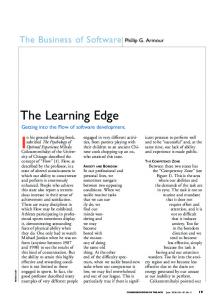
Fig. 1. Overview of the resiliency analysis framework: The framework is composed of (i) the front-end stage generating the fault injection-ready gate-level netlist and (ii) the back-end stage performing fault injection and analysis and generating the final resiliency analysis report.
translation that generates the fault-injection ready gate-level netlist of the design under analysis, and (ii) the back-end fault simulation and analysis that performs the actual fault injection and fault monitoring and evaluates the effects of the injected faults. Figure 1 represents an overview Crashtest. A FPGA solution is the only one that can provide enough performance to run software applications on large and complex designs. However, a major cost in the adoption of this solution is the overhead necessary to map the design on the FPGA fabric. For big designs the time needed to obtain the netlist mappable on the FPGA device can be prohibitively long. To reduce this overhead, in Crashtest multiple faults are inserted in the netlist mapped on the FPGA. These faults can be singularly activated dynamically through software, thus sharing the mapping cost on several analysis. Framework Front-End: First, the HDL model of the design under analysis is provided by the user (either in Verilog or VHDL). Subsequently, the HDL model of the design is synthesized by the front-end stage of the framework using a standard cell library to get a gate-level netlist of the design. CrashTest does not require the design to be mapped with any particular library as long as it is properly modified to support the fault models. For each standard cell in the library (i.e., a combinational gate or a sequential element), CrashTest is enhanced with a gate-level logic transformation that modifies the netlist and inserts extra fault injection logic. This extra logic can be activated at runtime to emulate the effects of a fault injected into the cell. We developed a wide range of fault models and gate-level logic transformations to provide the capability of emulating different failure mechanisms. The collection of all logic transformations is stored in the framework’s fault library. Based on the injection parameters selected by the user (i.e., the fault models and the injection locations), the framework automatically generates the fault injection-ready netlist of the design using the logic transformations in the library. This netlist is then delivered to the fault analysis simulator at the back-end stage. Framework Back-End: At the framework back end, the fault injection-ready netlist is re-synthesized and mapped on an FPGA. At this point the fault injection and analysis campaign is ready to begin. Based on the fault simulation parameters given by the user, the fault injection/analysis emulator injects faults at different sites in the netlist and
monitors their propagation and impact on the design and the running applications. During fault emulation, the design under analysis is exercised with the application stimuli. To gain statistical confidence on the provided results, the experiments are repeated in a Monte Carlo simulation model by altering the fault sites and/or the application stimuli. After running a sufficient number of experiments to gain statistical confidence, the results are aggregated into the resiliency analysis report which is the final deliverable of the CrashTest framework. In the following sections, we describe each step of the CrashTest framework in more detail. IV. G ATE -L EVEL FAULT I NJECTION M ETHODOLOGY Technology Independent Logic Synthesis - The first step in the front-end stage of the CrashTest framework is to convert the user-provided high-level HDL model of the design under analysis into a common format that the framework can analyze and get an accurate list of candidate circuit locations to perform gate-level fault injection. This is achieved by performing logic synthesis with Synopsys Design Compiler targeting a technology-independent standard cell library (GTECH). The resulting gate-level netlist is composed of simple logic gates (e.g., AND, OR, NOT, FlipFlops, etc,) and it is free from any fabrication technology related characteristics and properties. This gate-level netlist is subsequently parsed to generate a list of all possible fault injection locations in the circuit (i.e., a list of all logic gates and flip-flops in the design). This list is used by the user to specify the fault injection locations; alternatively, if randomized fault injection is desired, random selection of fault sites can be performed by the framework. Netlist Fault Injection Instrumentation - Once fault locations are selected, the gate-level netlist is instrumented with extra fault injection logic that, when enabled, emulates the effects of the injected faults. Each fault model supported by the framework is associated with a gate-level logic transformation that modifies the netlist and instruments it with the extra fault injection logic. The collection of gate-level logic transformations composes the framework’s fault library. This modular design makes it fairly easy to upgrade the framework with new fault models by simply implementing and adding new netlist logic transformations into the fault library. Our resiliency analysis framework is already enhanced with a collection of fault models and their corresponding netlist logic transformations. This fault model
Transistor-level NAND2 gate Vdd A
B C B
n1
A Gnd
Fault Symptom Table
Instrumentation logic for Bridge-A-B
A
0
1
0
1
B
0
0
1
1
Fault-Free
1
1
1
0
Bridge-A-B
1
X
X
0
Bridge-A-C
X
1
X
X
Bridge-A-n1
1
1
1
X
Bridge-B-n1
1
X
1
X
Bridge-B-C
X
X
1
X
Bridge-C-n1
1
1
X
0
A B
0 C
Random Value
A B A B
1
Fault Inject
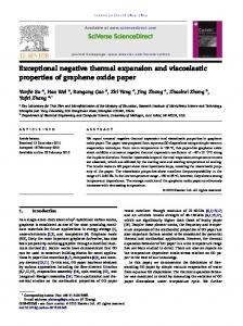
(a) (b) (c) Fig. 2. Logic Transformations - Bridge Fault: The CMOS transistor-level design of a gate in (a) is used to generate the gate’s fault symptom table for the fault model shown in (b). Part (c) shows the instrumentation logic for emulating the effects of the Bridge-A-B fault. Fault-Injection Ready Netlist
Stuck-at: The stuck-at fault model is the industry standard model for circuit testing. It assumes that a circuit defect behaves as a node stuck at logical 0 or 1. The stuck-at fault model is most commonly used to mimic permanent manufacturing or wearout-related silicon defects. Stuck-open: The stuck-open fault model assumes that a single physical line in the circuit is broken. The unconnected node is not tied to either Vcc or Gnd and its behavior is rather unpredictable (logical 0 or 1 or high impedance). The stuck-open fault model is commonly used to mimic permanent defects that are not covered by the stuck-at fault model. Bridge: The bridge fault model assumes that two nodes of a circuit are shorted together. The behavior of the two shorted nodes depends on the values and the strength of their driving nodes. The bridge fault model covers a large percentage of permanent manufacturing or wearout-related defects. Path-delay: The path-delay fault model assumes that the logic function of the circuit is correct, however, the total delay in a path from its inputs to outputs exceeds the predefined threshold and it causes incorrect behavior. The path-delay fault model is most commonly used to mimic the effects of process variation or device degradation due to age-related wearout. Single Event Upset: The single event upset (SEU) fault model assumes that the value of a node in the circuit if flipped for one cycle. After this one cycle upset, the node behaves as expected. The SEU fault model is used to mimic transient faults that are most commonly used by cosmic radiation or alpha particles.
TABLE I Fault models: CrashTest is enhanced with an extensive collection of fault models. These fault models cover transient faults as single event upsets and also a variety of permanent hard faults related to manufacturing, wearout, and process variation silicon defects.
collection covers an extensive spectrum of silicon failure mechanisms ranging from transient faults due to cosmic rays to permanent faults due to silicon wearout. Table I shows a list of supported fault models with a brief description. Gate-Level Logic Transformations - Some fault models require trivial gate-level logic transformations. For example, the instrumentation needed to emulate a stuck-at fault is just a multiplexer that controls the output of the faulty gate and has one of its inputs connected to logic zero/one. However, there are fault models that are more complex and affect the design at the transistor level. For example, the bridge fault model assumes that two nodes in the design are shorted together. To emulate the effect of a bridge fault model with high fidelity, we simulated the faulty gates at the CMOS transistor level and generated the corresponding fault symptom tables. To illustrate this process, Figure 2(a) shows the CMOS transistor level representation of a NAND2 logic gate, while Figure 2(b) shows the respective fault symptom table of the
Fault Injection Site 1 FI Scan In
D
Q Clk
… …
Fault Injection Site 2
Fault Injection Site N
FI D
Q Clk
FI D
Q
Scan Out
Clk
Fault Injection Scan Chain
Fig. 3. Fault injection scan chain: The netlist is instrumented with fault injection logic for multiple faults. The scan chain controls the fault injection during emulation.
bridge fault model. By observing the fault symptom table we noticed that for some inputs the effects of the fault are masked, thus the faulty gate behaves exactly like a fault-free gate. However, for other input combinations the fault’s effects propagate to the gate’s output and result in an unstable output signal that could be either a logic zero or one (Random Value in Figure 2(c)). The framework’s fault library is populated with a fault symptom table for each combination of a standard cell library gate and a supported fault model. Given the gate type and the fault model, the netlist instrumentation routine accesses the fault library and applies the respective logic transformation that would insert the necessary instrumentation logic to emulate the fault effects. Figure 2(c) shows the instrumentation logic needed to emulate the effects of a bridge fault between the circuit nodes A and B of the NAND2 gate. A fault-tolerant design should be able to handle these faults and either mask the errors introduced or reconfigure itself to not use the faulty part of the design. Fault Injection Scan Chain - To avoid re-instrumenting the netlist each time a new fault is injected and simulated, the netlist can be instrumented for multiple faults at multiple locations. This accelerates the fault emulation at the backend of the framework, but it also increases the instrumented circuit size. The insertion of each fault into the netlist also adds an extra control signal used for enabling and disabling the inserted fault at runtime (for instance, signal Fault Inject and Random Value in 2(c)). During emulation, these signals are accessible by the Fault Injection Manager (see Figure 5). The Path-Delay Fault Model - The gate-level logic transformations employed for the rest of the supported fault models are similar to the one presented in Figure 2(c) for the bridge fault. One exception is the path-delay fault model
Affected Flip-Flops
D
Q
1 Combinational Logic D
FI
…
Faulty Gate
Clk
Q Clk
0 D
Q
1 Clk FI
Fig. 4. Logic transformation for the path-delay fault model: If the output of the faulty gate changes in a given cycle, all affected flip-flops miss latching the newly computed value and hold the previous cycle’s value.
which has slightly different characteristics. Path-delay faults are characterized by slower combinational logic gates that cause longer path delays than the ones expected at design time. Whenever these slower gates get exercised, they can increase the path delay beyond the critical path delay and cause timing violations (i.e., the flip-flops at the end of the path miss to latch the newly computed value). In our framework, the effects of the path-delay fault model are emulated by the gate-level logic transformation shown in Figure 4. To determinate the set of flip-flops that are affected by the slower faulty gate, we trace forward through the combinational logic and find all those flip-flops that have a path that includes the faulty gate. From that set of flipflops we choose only those that have a path delay with a timing slack smaller than a predefined threshold specified by the user (i.e., the expected delay due to the faulty gate). V. FPGA-BASED FAULT E MULATION CrashTest employs an FPGA platform to emulate the fault injected hardware and accelerate the fault simulation and analysis process. The first step in this process it to synthesize and map the fault injection-ready netlist to the target FPGA. To provide a standard simulation interface that is independent of the design under analysis, we add an automatically generated interface wrapper to the fault injected-ready netlist. This interface wrapper provides a seamless connection with the fault injection manager, which is an automatically generated software program responsible for orchestrating the fault injection and analysis campaign. The interface wrapper and the fault injection manager are connected through an on-chip interconnect bus. Figure 5 shows the major components and the data-flow of the fault injection, simulation and analysis process. Fault Injection Manager - During the emulation and analysis process, the FPGA-mapped design is exercised and controlled by the fault injection manager. In our experiments we used a Xilinx Virtex-II Pro FPGA, which has two onchip PowerPC processors, with the fault injection manager software running on one of them. Alternatively, the fault injection manager can also run on a soft-core (e.g., Microblaze). Specifically, the fault injection manager is responsible for the following tasks:
Instrumented Fault-Injection Ready Netlist
Input Registers
0
FIFO
Interface Wrapper Interrupt Counter Output Registers
Gate-Level Logic Transformation for the Path-Delay Fault Model
On-chip Processor Core Fault Injection Manager
Off-chip Memory - Stimulus - Fault injection parameters - Golden results - Results/Statistics
Fig. 5. FPGA-Based fault injection and simulation: The FPGA-mapped netlist is wrapped by a standard interface providing a seamless connection to the fault injection manager that is running on an on-chip processor core.
- Feed the instrumented injection scan chain with all the control signals required to perform the fault injection campaign. This is done through a FIFO queue updated whenever a new fault is injected into the design. The fault injection parameters (i.e., fault location and time) are stored on an off-chip memory accessible by the fault injection manager. - Stimulate the design through the input registers. The applications stimulus is either provided by the user or automatically generated, and it is stored in the off-chip memory. - Monitor the output of the FPGA-mapped design for errors through the output registers. The output is compared to a golden output that is collected through a fault-free version of the same design and it is stored in the off-chip memory. - Maintain fault analysis statistics and store the results to the off-chip memory for later processing. - Synchronize the FPGA-mapped design with the fault injection process through the interrupt counter. VI. F RAMEWORK E VALUATION In this section, we evaluate our FPGA-based resiliency analysis infrastructure and compare its performance to an equivalent software-based implementation. We also perform an initial examination, using the CrashTest infrastructure, of the effects of different fault models in design resiliency. A. Experimental Methodology Benchmark Designs - For the evaluation of CrashTest we used three benchmark designs. These benchmark designs and their characteristics are shown at Table II. The chip-multiprocessor (CMP) interconnect router implements a wormhole router pipelined at the flit level with creditbased flow control functionality for a two-dimensional torus network topology [13]. We used SPEC CPU2000 communication traces derived from the TRIPS architecture [18] to provide application stimuli to the router. The DLX core is a 32-bit 5-stage in-order single-issue pipeline running the MIPS-Lite ISA. Finally, the LEON3 is a system-onchip including a 32-bit 7-stage pipelined processor running the SPARC V8 architecture, an on-chip interconnect, basic peripherals and a memory controller [10]. The LEON3 SoC is able of booting an unmodified version of Linux 2.6. The LEON processor was configured without on-chip caches and faults were injected only in the core component. Netlist Fault-Injection Instrumentation - The HDL model of the design under analysis is synthesized using the Synopsys Design Compiler and the GTECH standard cell library. The resulting netlist is a technology-independent
Benchmark Logic Gates Name (GTECH)
Flip Flops
CMP Router
16,544
1,705
DLX Core
15,015
2,030
LEON3 Systemon-chip
66,312
6,925
Description chip-multiprocessor interconnect router for a 2D mesh network with 32-bit flits 5-stage in-order DLX pipeline running MIPS-Lite ISA System-on-chip with a 7-stage pipeline 32-bit processor compliant with the SPARC V8 architecture, an on-chip interconnect, basic peripherals and a memory controller.
TABLE II Benchmark Designs: Characteristics of the benchmark designs used to evaluate the CrashTest framework. Confidence Level = 95% Number of Fault Injections (Sample Size) 256 512 1024 2048 4096 8192
Confidence Interval CMP Router DLX Core LEON3 (18249 gates) (17045 gates) (73237 gates) 6.08 6.08 6.11 4.27 4.27 4.32 2.98 2.96 3.04 2.04 2.03 2.14 1.35 1.33 1.49 0.8 0.78 1.02
TABLE III Statistical Confidence: The Table shows the confidence level of the results obtained when different number of faults are injected during the injection campaigns for our benchmark designs.
GTECH gate-level netlist. The gate-level netlist is then analyzed by Perl scripts which locate all the possible injection sites in the circuit. Once the sites and fault types are selected (using a uniform random distribution for these experiments), a Perl script implements gate-level logic transformations to instrument the netlist with the necessary fault injection logic. Software-Based Analysis Methodology - The softwarebased fault simulation and analysis is performed using the Synopsys VCS logic simulator for the CMP router and the DLX core. For the simulation of the LEON3 system-on-chip we used ModelSim, since it required the simulation of both Verilog and VHDL modules. The fault simulations using VCS were run on an Intel Core 2 Duo running at 2.13GHz with 2GB of RAM; while the ModelSim simulations were run on a P4 at 3.4GHz and 2GB RAM. FPGA-Based Analysis Methodology - For the FPGAbased fault emulation and analysis we used the XUP V2P Development Board [1]. The board is equipped with a Virtex2 Pro XC2VP30 FPGA with 13,696 slices (each with two 4-input LUTs and two flip-flops), and two PowerPC 405 processors. At the time of writing, this FPGA represented a mid-sized device; devices with up to 10X as many resources are currently available. For off-chip memory we used one 256MB module of DRAM. The main tools used to develop the CrashTest framework are the Xilinx Platform Studio (XPS) version 9.1i in combination with Xilinx Integrated Software Environment 9.1i (ISE). We also used Synplicity’s Synplify 9.0.1 for the FPGA-based synthesis. The FPGA synthesis and mapping process was ran on a P4 CPU at 3.0Ghz and 1GB RAM. The synthesis and mapping process for the LEON3 system took about 45 minutes, while the other two benchmark designs required significantly less time. B. Monte Carlo Simulation & Statistical Confidence Performing gate-level fault injection campaigns in complex designs and observing their impact at the application level is a fairly computationally intensive process. The prop-
Bench. Design
Injected Faults
Slices (out of 13696)
0 (baseline) 2968 (21%) 0 (wrapper) 6679 (48%) 8 6718 (49%) 64 6912 (50%) CMP Router 128 7161 (52%) 256 7279 (53%) 512 7854 (57%) 1024 8903 (65%) 0 (baseline) 2499 (18%) DLX 0 (wrapper) 6820 (49%) Core 1024 9593 (70%) LEON3 0 (baseline) 10281 (75%) System- 0 (wrapper) 11057 (80%) on-chip 1024 11785 (86%)
Slice Flip 4 Input LUTs Flops (out of 27392) (out of 27392) 3021 (11%) 3705 (13%) 4731 (17%) 10840 (39%) 4745 (17%) 10781 (39%) 4857 (17%) 11192 (40%) 4985 (18%) 11408 (41%) 5241 (19%) 11425 (41%) 5753 (21%) 12020 (43%) 6778 (24%) 13059 (47%) 2520 (9%) 2386 (8%) 8202 (29%) 4573 (16%) 6700 (24%) 9948 (36%) 10178 (37%) 20562 (75%) 11103 (40%) 22113 (80%) 13146 (47%) 23570 (86%)
TABLE IV Fault injection logic overhead: Utilization of the FPGA resources comparing the baseline (fault-free) designs and the fault injection instrumented designs mapped on the FPGA.
agation of fault effects from the gate level to the application level requires a significant amount of gate-level simulation of the design under analysis. To reduce the number of fault injections and make computationally tractable the resiliency analysis process, Monte Carlo simulation methods are adopted. Through Monte Carlo simulation, fault injection experiments are repeated by randomly changing the fault injection location and time (i.e., the clock cycle that the fault will be enabled). The number of times that the Monte Carlo experiments are repeated depends on the desired statistical confidence that will characterize the obtained results. Table III shows the confidence intervals for different numbers of fault injection experiments for the three benchmark designs. These figures were calculated using the statistical sample size formulas from [3]. For most applications, a confidence level of 95% and a confidence interval of 3% are acceptable. From Table III we noticed that this degree of statistical confidence can be achieved by 1024 fault injections for all three benchmark designs. C. Framework Performance Fault Injection Logic Overhead - Table IV shows the allocated FPGA resources when the baseline (fault-free) benchmark designs were synthesized and mapped on the FPGA. When the designs are augmented with the fault simulation interface wrapper the utilization of the FPGA slices is increased from 15% to 31%. As shown in the fourth and fifth columns of Table IV, not all of the flip-flops and LUTs in each utilized slice are used. The table also shows the overhead of the instrumentation logic for designs injected with different numbers of stuck-at faults. The capability of injecting several faults into the design is very important since it significantly accelerates the fault simulation process by avoiding time-consuming iterations of netlist instrumentation and FPGA synthesis/mapping. Fault Simulation/Analysis Speed - Table V compares the speed of the software-based and the FPGA-based fault emulation and analysis engines. For the CMP router design we noticed that the speed of the software-based scheme varied for different fault models. This difference stems from the
A ?@ >2 =9 87 56 2 : 78 4< 7 4; 4: 9
78 56 42 3 12 /0
100 90 80 70 60 50 40 30 20 10 0 �
�
� � � � � �
�� �
�
� �
�� �
��
� ��
� �
�� � � �
��
��
�
� � � �� �
�� ��� � �� ��
�
� � � � � � �
�
�� �
�
� �
�� �
��
� �
��
� �
� � � � �
� �
��
�
� � � � � �
�� �� � � !"# � �
�
��� � � �
�
�� �
�
��
� � �
��
� �
��
� �
� � � � �
��
��
� �
�
�� � � � �
� � � �� �
�� �
�
��
� � �
� �
��
�
��
� � � � � �
�� ��� � '( � &
�� �� � � �$ � � � � %
� �
��
� �
� � � � �
�
� � � � � �
�
�� �
�
��
� � �
��
� ��
� �
��� � �
� �
��
�
� � � � � �
�� �� � � " �)� � � �
�
� �� � � � �
��
�
�
�
��
� � �
��
� �
��
� �
� � � � �
� �
��
�
� � � � � �
�
�
��
�� ��� � )* ! � &
� �
� � �
�
�� �
��
� �
��
� �
�� �
��� � � �
��
��
�
� � � �� �
�� �� � � � ���, �+
� � � � �
� �� � � �
��
��
�
�
�
� �
�
��
� ��
�
� �
��
��
�
�
� � � �� �
�� �� � � ! �� !. � -�
Fig. 6. Design Resiliency vs. Underlying Fault Model: Percentage of injected faults that were exposed for each fault model. Experiments are run on the CMP router using SPEC2000 traces. Bench. Design
CMP Router
LEON3 Systemon-chip
Fault Model Stuck-at-0 Stuck-at-1 Stuck-open Bridge Path-delay SEU
Software-Based Fault Simulation Speed 9.75 KHz 8.09 KHz 2.42 KHz 2.63KHz 11.34 KHz 13.04 KHz
FPGA-Based Fault Simulation Speed
Speed Up
220 KHz
22X 27X 90X 83X 19X 16X
Stuck-at-0
28 Hz
25 Mhz
~900 000X
TABLE V Fault simulation speed: Performance comparison of the software- and FPGA-based fault simulation engines.
different logic complexity required to emulate the behavior of each fault model. On average, for the CMP router the software-based scheme provides a simulation speed that is in the order of 10 KHz. We have observed similar results for the DLX core design (not shown in the table for brevity). On the other hand, the speed of the FPGA-based scheme is not affected by the fault injection logic. Therefore, all fault models are emulated with the same clock frequency and achieve the same emulation speed. For the CMP router, the speed of the emulation framework is 220 KHz, leading to an average speed up of ≈20X for simple fault models and ≈85X for the more complex fault models. The simulation speed achieved by the software-based scheme when analyzing the LEON3 system-on-chip is much lower than the one observed for the other two simpler designs (i.e., the CMP router and the DLX core). Specifically, the simulation speed is limited to 28 Hz, due to the much higher complexity of the full-system LEON3 design. In contrast, the emulation speed of the LEON3 system on the FPGAbased scheme is faster than the other two simpler designs. This is due to how the application stimulus is applied to different designs by the fault injection manager. Since the LEON3 full-system design includes a memory controller, the interaction with the external environment is limited to memory read/write requests, which are served by the off-chip DRAM module. Therefore, in the LEON3 analysis there is very little interaction between the fault injection manager and the design under analysis in feeding the application stimulus. On the other hand, when emulating the other two designs, the fault injection manager must provide input stimuli cycle-bycycle in order to drive the emulation, thus limiting the overall performance. The emulation speed of the LEON3 design on
the FPGA-based scheme is 25 MHz, which leads to a six orders of magnitude speedup compared to the corresponding simulation speed achieved by the software-based scheme. D. Experimental Results Fault Effects per Fault Model - The graph in Figure 6 shows the percentage of injected faults that caused a failure, grouped by fault model. The fault injection experiments were run on the CMP router stimulated with communication traces of several SPEC CPU2000 benchmarks and a synthetic hightraffic communication trace (hi util). We observe that the effects of the injected faults on the design vary for different fault models. Specifically, fault models of permanent silicon failures (i.e., stuck-at, stuck-open, and bridge) have more adverse effects on the design, and 70-80% of them cause an error that is observable at the primary outputs of the design during the emulation. On the other hand, the path delay fault model has less adverse effects, and on average only 40% of these faults manifest an error. Finally, the SEU faults have the least impact on the correct functionality of the design and on average less than 10% of them cause an error. Failure Observation Latency - The graph in Figure 7 shows the average latency of an injected fault to propagate an error to the primary outputs of the design. The results shown are for different fault models for the CMP router and the LEON3 system-on-chip. The failure observation latency is a very important metric when assessing the resiliency of a design because it provides insight on whether specific error detection and recovery techniques can provide a detection and recovery window that would allow a successful recovery from the fault’s effects. We noticed that the failure observation latency varies depending on the fault model. Specifically, we observed that for the CMP router the injected path-delay faults have the highest failure manifestation latency, while fault models associated with permanent failure mechanisms usually have similar failure manifestation latencies. Furthermore, we noticed that the error manifestation latency for SEU faults is very small. When this observation is combined with the results of the previous experiment, we concluded that SEU transient faults either cause an error in the design immediately after they occur, or they do not cause an error at all, as would be expected due to their transient nature. We also noticed that the measured failure observation
Cumulative Faults Injected (%)
Average Latency in Detecting a Failure (Cycles)
1,000,000,000
1,000,000
1,000
1
100 90 80 70 60 50 40 30 20 10 0
Injected faults that did not cause an error during the simulation Stuck-at-1 Stuck-at-0 0
CMP Router
LEON3
Fig. 7. Failure Detection Latency: Failure observation latency at the design’s primary outputs.
latencies for the LEON3 system-on-chip are orders of magnitude larger than the ones observed for the CMP router. This difference stems from the higher complexity of the LEON3 system-on-chip which leads to more cycles required for a fault to propagate to the design’s output (the output of the running application). To give more insight regarding the failure observation latency of the faults injected in the LEON3 system, the graph of Figure 8 shows the cumulative distribution of the injected faults over the failure observation latency in clock cycles. An interesting observation is that more than half of the injected faults propagate a failure to the application output almost immediately, but the remaining ones require billions of cycles for the failure to manifest. This observation supports the argument that if a fault hits a critical part of the design, then its effect are immediate. On the other hand, if it hits a less critical/exercised part of the design, then its effects are delayed by long latencies. VII. C ONCLUSIONS & F UTURE W ORK In this paper we presented CrashTest, a novel FGPAbased resiliency analysis framework capable of automatically orchestrating a fault injection and analysis campaign on the gate-level netlist of the design. To accelerate the fault injection process multiple faults are injected into the design simultaneously by instrumenting the netlist with fault injection logic through gate-level logic transformations. The framework supports an extensive collection of fault models ranging from transient faults to silicon defects, and it can easily be upgraded with new fault models. We evaluated our framework on an FPGA-based platform, and we found that the use of hardware emulation can accelerate the fault simulation and analysis process by 16-90x for simple designs and six orders of magnitude for a more complex system-onchip design, when compared to an equivalent software-based simulator, while providing an accurate fault model. The work presented here is the first step toward the implementation of a widely usable resiliency analysis infrastructure on an FPGA-based emulation platform [8]. We are currently working on porting the existing infrastructure to the BEE2/RAMP platform [8, 22], thereby making it widely available to researchers that are migrating to this FPGAbased performance analysis platform. The BEE2 platform will enable the analysis of even more complex designs, and will further improve the fault simulation speed and analysis
1E+09 2E+09 3E+09 4E+09 5E+09 Failure Detection Latency (Cycles) Fig. 8. Application-level Detection Latency: Latency (in cycles) for a stuck-at fault to propagate to the application results in the LEON3 SoC.
quality since more resources will be available for the fault injection instrumentation logic and the fault analysis process. VIII. ACKNOWLEDGMENTS We acknowledge the support of the Gigascale Systems Research Center (GSRC), National Science Foundation and Semiconductor Research Corporation. R EFERENCES [1] Xilinx University Program: Xilinx XUP Virtex-II Pro Development System. http://www.xilinx.com/univ/xupv2p.html, 2005. [2] T. M. Austin. DIVA: A reliable substrate for deep submicron microarchitecture design. In MICRO-32, 1999. [3] J. E. Bartlett et al. Organizational research: Determining appropriate sample size in survey research. Information Technology, Learning, and Performance Journal, 19(1):43–50, 2001. [4] S. Borkar. Microarchitecture and design challenges for gigascale integration. In MICRO, Keynote Presentation, 2004. [5] S. Borkar et al. Design and reliability challenges in nanometer technologies. In DAC-41, 2004. [6] F. A. Bower et al. A mechanism for online diagnosis of hard faults in microprocessors. In MICRO, 2005. [7] M. L. Bushnell et al. Essentials of Electronic Testing for Digital, Memory and Mixed-Signal VLSI Circuits. Kluwer Academic Publishers, Boston, 2000. [8] C. Chang et al. BEE2: A high-end reconfigurable computing system. IEEE Design & Test of Computers, 22(2), 2005. [9] P. Civera et al. FPGA-based fault injection techniques for fast evaluation of fault tolerance in VLSI circuits. Lecture Notes in Computer Science, 2147, 2001. [10] J. Gaisler. A portable and fault-tolerant microprocessor based on the SPARC V8 architecture. In DSN, pages 409–415, 2002. [11] R. Guo et al. Evaluation of test metrics: Stuck-at, bridge coverage estimate and gate exhaustive. In VTS, 2006. [12] G. A. Kanawati et al. FERRARI: A flexible software-based fault and error injection system. IEEE Trans. Computers, 44(2):248–260, 1995. [13] Li-Shiuan Peh. Flow Control and Micro-Architectural Mechanisms for Extending the Performance of Interconnection Networks. PhD thesis, Stanford, 2001. [14] C. L´opez-Ongil et al. An autonomous FPGA-based emulation system for fast fault tolerant evaluation. In FPL, 2005. [15] C. McNairy and R. Bhatia. Montecito: A dual-core, dual-thread Itanium processor. IEEE Micro, 25(2):10–20, 2005. [16] Mei-Chen et al. Fault injection techniques and tools. IEEE Computer, 30(4):75–82, Apr. 1997. [17] G. P. Saggese et al. Microprocessor sensitivity to failures: Control vs execution and combinational vs sequential logic. In DSN, 2005. [18] K. Sankaralingam et al. Exploiting ILP, DLP, and TLP using polymorphism in the TRIPS architecture. In ISCA, 2003. [19] D. P. Siewiorek and R. S. Swarz. Reliable computer systems: Design and evaluation, 3rd edition. AK Peters, Ltd, 1998. [20] J. Srinivasan et al. The impact of technology scaling on lifetime reliability. In DSN-34, pages 177–186, 2004. [21] N. J. Wang et al. Characterizing the effects of transient faults on a high-performance processor pipeline. In DSN, 2004. [22] J. Wawrzynek et al. RAMP: A research accelerator for multiple processors. Technical report, Berkeley, Nov. 2006.