Sep 9, 2010 - co-registration of bone surfaces through constrained local and global ... field over the spatial domain to avoid distorting the template excessively [ZF03]. Hence ... these static methods generate plausible results at a cheaper.
Author manuscript, published in "Computer Graphics Forum (2010) http://onlinelibrary.wiley.com/doi/10.1111/ j.1467-8659.2010.01718.x/abstract" DOI : 10.1111/j.1467-8659.2010.01718.x
Volume xx (200y), Number z, pp. 1–10
Creating and animating subject-specific anatomical models B. Gilles 1 , L. Revéret2 and D. K. Pai 1 1
Department of Computer Science, University of British Columbia, Canada 2 EVASION, INRIA Rhône-Alpes, France
inria-00516374, version 1 - 9 Sep 2010
Abstract Creating and animating subject-specific anatomical models is traditionally a difficult process involving medical image segmentation, geometric corrections and the manual definition of kinematic parameters. In this paper, we introduce a novel template morphing algorithm that facilitates 3D modeling and parameterization of skeletons. Target data can be either medical images or surfaces of the whole skeleton. We incorporate prior knowledge about bone shape, the feasible skeleton pose, and the morphological variability in the population. This allows for noise reduction, bone separation, and the transfer, from the template, of anatomical and kinematical information not present in the input data. Our approach treats both local and global deformations in successive regularization steps: smooth elastic deformations are represented by an displacement field between the reference and current configuration of the template, while global and discontinuous displacements are estimated through a projection onto a statistical shape model and a new joint pose optimization scheme with joint limits. Categories and Subject Descriptors (according to ACM CCS): I.3.5 [Computer Graphics]: Computational Geometry and Object Modeling—Physically based modeling
1. Introduction Biomechanics-based animation offers an exciting degree of realism as shown in recent studies [KM04,TSB∗ 05,SKP08]. These methods require, however, accurate geometric models of bones and soft-tissues (muscles, skin, ligaments and cartilages). Their creation is usually time-consuming and needs to be performed independently for each subject, making such approaches impractical for graphics applications. Although there are semi-automatic methods to extract bones from medical images (e.g., thresholding of Computed Tomography images) [KM04], a significant manual work is always still required: bone separation, labeling, definition of the animation skeleton, soft-tissues segmentation and geometric corrections . In this paper, we tackle this problem through a new co-registration method that can automatically align generic skeletons to multi-modal data (surfaces and images). The key idea is to mix local deformations and a global registration to recover both the morphology and the pose of the target skeleton. Our new regularization method combines shape, statistical and joint limits constraints, and allows us to treat noisy and low resolution models and images. We are submitted to COMPUTER GRAPHICS Forum (9/2010).
also able to transfer features from the template (geometric details, animations) that were not necessarily acquired with the considered modality. Registration aims at finding spatial correspondences between datasets. In other words, the goal is to find a deformation field that aligns a template to a target dataset. It is a central problem in the computer graphics and image processing communities [AFP00, ZF03]. The main difficulties are to find an adequate similarity measure that is as-convexas-possible and a good parameterization of the deformation through the introduction of prior information. Registration has been mainly studied in the context of rigid alignment and small deformations. The musculoskeletal system however presents a large geometric variability in terms of morphology and pose. It makes registration difficult by increasing the number of local minima. Our method addresses these issues by performing a robust co-registration of bone surfaces through constrained local and global deformations. Constraints are applied by regularizing an initial correspondence vector field between the datasets (Section 3.2). . Smooth elastic deformations, ac-
2
B. Gilles & L. Revéret and D.K. Pai /
inria-00516374, version 1 - 9 Sep 2010
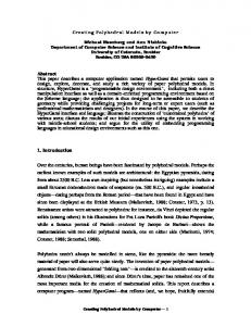
Figure 1: Our method automatically warps template skeleton models to subject-specific anatomy and posture (left figure: hand registration; right figure: rat/dog). This allows transferring generic geometric details and animations (middle figure: transfer of hand soft-tissues and posture)
counting for morphological differences, are represented by an displacement field between the reference and current configuration of the template (Section 3.3). The global evolution is ensured by a projection to a statistical shape model (Section 3.4) and a new joint pose optimization scheme with joint limits (Section 3.5). Finally, in Section 4, we illustrate the benefits of our methods through the automatic registration of a human hand model and a rat model to manually segmented surfaces and to Magnetic Resonance Images (MRI). As a result, we obtain subject-specific models, with smooth separated bones, that can be directly animated. We show how geometric and kinematic information can be mapped from the template to the target.
2. Related work Registration consists in iterating two basic steps: first, the distance between the current position of the template and the target is estimated; secondly, this distance is minimized by deforming the template [AFP00, ZF03]. One class of methods, called variational methods, globally evolves the model along its degrees of freedom in order to minimize the distance. Alternatively, pair-and-smooth approaches locally minimize the distance through correspondence computations, and then regularize those displacements to satisfy deformation constraints. This approach is more suited in our context since our system has a high number of coupled degrees of freedom. It allows treating shape and inter-object constraints in successive regularization steps. Correspondence computation: In discrete models, correspondences are defined for each vertex as the displacement that maximizes a certain similarity measure. Extrinsic similarity measures, based on the current configuration of the
surfaces in the Euclidean space, are widely used for simplicity [BBK09]. The popular Iterative Closest Point algorithm (ICP) results from the computation of closest points between the template and target surfaces [BM92]. In image registration, pairing is performed by locally maximizing the image similarity between the template image and target image. Several correlation measures have been proposed for a range of imaging modalities [ZF03]. Local pairing is not robust for large displacements however, unless there are few degrees of freedom and a clear global minimum. Robust correspondences can be better achieved by computing similarity over the entire spatial domain. In surface registration, researchers have considered the distance between rotation and translation invariant local shape descriptors, built from differential geometric quantities [HAWG08] . Similarly, features can be extracted from images based on the local intensity distribution [ZF03], such as the histogram moments [She07]. Contrary to closest point methods, feature correspondence needs propagation and smoothing steps to ensure a local consistency of the alignement [HAWG08]. Optimization of the pairing stage has been studied through voting techniques that minimize distortions of the template after registration [LF09, ZSCO∗ 08]. Intrinsic properties of shapes, such as geodesic distances, are interesting because they are quasi-invariant under object pose and current deformation. Shape embedding techniques have been developed to enhance such properties, such as in spectral embedding methods [MHK∗ 08], conformal mapping [LF09] or the medial axis transform [SSGD03]. Intrinsic methods attempt to find common parameterizations between template and target surfaces. They are global but sensitive to topological noise [BBK09]. As-rigid-as-possible deformation: Most surface and image submitted to COMPUTER GRAPHICS Forum (9/2010).
B. Gilles & L. Revéret and D.K. Pai /
inria-00516374, version 1 - 9 Sep 2010
registration techniques assume a smoothly varying motion field over the spatial domain to avoid distorting the template excessively [ZF03]. Hence, regularization techniques typically try to enforce . The simplest way is to perform rigid registration to recover the dominant motion. The iterative closest point (ICP) algorithm [BM92] is a widely used approach that finds, at each iteration, the best rigid transform approximating the current target displacements. In the generalized gradient approach [CMP∗ 07], target displacements are filtered to remove non-isometric components from the deformation field. In computer graphics, various techniques have been developed to generate as-rigid-as-possible deformations in order to mimic elasticity. Sorkine et al. [SA07] iteratively minimize a energy. Müller et al. [MHTG05] blend closest rigid transforms in their shape matching framework. While the assumption of smooth displacements is acceptable for a single object, it is inaccurate at boundaries when the relative displacement between objects is large, which is the case for bones (see Fig. 2). In this context, researchers have tried to design piecewise quasi-isometric displacements fields. Arsigny et al. [ACPA06] introduced polyrigid and polyaffine transformations for image registration. Wang et al. [WHQ05] proposed a spline-based deformation technique that incorporates rigid components. For registering the skeletal system, articulated rigid motion has been considered in [KM04, STC∗ 03, PDD∗ 05]. Contrary to us they do not handle joint limits, relative translations and cyclic skeletal structures, and do not perform a simultaneous non-rigid registration. In motion capture, the underlying pose of the animation skeleton is computed from fiducial marker correspondences. Energy minimization approaches have been developed such as in [ACP02]. In [OBBH00], O’Brien et al. compute joint centers from markers motion (i.e., they register an acyclic chain of scalable rigid bodies). To smoothly deform surrounding soft-tissues from the articulated motion, numerous skinning techniques have been proposed in the graphics community. For skin registration, skeletal subspace deformation (or linear blend skinning) with an automatic tuning of influence weights has been presented in [VBMP08, HAWG08, CZ09]. Simulation of articulated rigid bodies: The fast simulation of constrained rigid bodies is an important and still open problem in computer graphics. Constrained dynamics approaches generate physically-based motion by solving the unknown constraint forces at contact or joint locations [Bar94]. Acyclic constraints between articulated bodies can be exactly and simultaneous enforced with a linear complexity in the number of joints either using generalized or maximal coordinates formulations [Bar96]. However, auxiliary constraints such a joint limits, contacts and loop closures require a specific treatment that is generally an iterative energy minimization process [Fau99, XWY∗ 09]. The introduced inequality relations make the system difficult to solve numerically (i.e linear complementary problem). Besides global optimization methods, a simple local method submitted to COMPUTER GRAPHICS Forum (9/2010).
3
Figure 2: Registration of a generic finger model to a manually segmented surface (a). The independent registration of the bones (c) and registration of the whole (d) present distortions and are sensitive to local minima (blue arrows), while our method (b) maintains realistic joint transforms and successfully decouples smooth and discontinuous deformations
that treats all joints sequentially consists in applying spring penalty forces to enforce constraints [MW88,XWY∗ 09], but suffers from stiffness and stability problems. Impulse-based methods [MC94, WTF06] solve this stability problem by altering the velocity of body pairs to guaranty a non violation of the constraint in the next frame. Another class of methods, into which our method falls, is the class of position-based methods. The goal is to procedurally adjust rigid body positions and orientations when constraints are not met [GC94,LBKH00]. Although not physically accurate, these static methods generate plausible results at a cheaper computational cost than constrained dynamics approaches. 3. Methods 3.1. Overview The purpose of the algorithm is to find a deformation field that aligns a discrete surface model of a skeleton (the template) to a surface or 3-dimensional image (the target). Let xr and x be the vertex position vectors of the template in the reference and deformed configurations. Figure 3 illustrates the different components of our registration framework. At each step of the process, correspondences v are estimated for each vertex (Section 3.2). For shape regularization, we approximate these correspondences with an asrigid-as-possible displacement field v˜ , where the distance to rigid motion is locally minimized (Section 3.3). This elastic registration process is continuously iterated and vertices are deformed through x = xr + v˜ until convergence. With plasticity, shapes undergo permanent changes: we update the reference positions xr . To derive global deformations, coherent with shape variability in the population, we project v onto principal components of a statistical model (Section 3.4). Finally, we adapt the reference skeleton pose with joint limit
4
B. Gilles & L. Revéret and D.K. Pai / Template model r reference positions x
Deformed positions x before plasticity
Correspondences v
1. As-rigid-aspossible fitting optimization Target
ELASTIC DEFORMATIONS
2. Statistical projection
PLASTIC DEFORMATIONS
the reference image. It is the concatenation of moments at different orders (n = 0, 1, 2) and different resolutions (s = s0 , 2.s0 , 4.s0 ) normalized between 0 and 1. During the registration, the similarity at the position (xri + v) in the target image is simply given by ∆i = Π j (1 − |a˜i, j − a(xri + v) j |). We find the correspondence vector v by maximizing ∆i in the neighborhood of the current position xi via a local search along the normal direction of the surface. A threshold of 0.2 is applied to avoid maxima with a small ∆i (see Fig. 4).
3. Joint pose evolution
Deformed positions x after plasticity
New reference r+ positions x
4. As-rigid-aspossible fitting ELASTIC DEFORMATIONS
inria-00516374, version 1 - 9 Sep 2010
Figure 3: Overview of our registration framework
constraints (Section 3.5). All these regularization steps allow incorporating shape, statistical and kinematic prior information. 3.2. Correspondence Computation In the section, we present how we compute target (unconstrained) vertex displacements for template-to-surface and template-to-image registration. Surface correspondences: Since features may not be clearly and uniquely identifiable in our datasets (e.g., fingers have quasi-similar shapes) and because of shape and topological noise (e.g., bones in close neighborhood), we apply a simple (extrinsic) closest point method: at each registration step, the deformed template (positions x) is projected to the target surface and vice-versa. Target displacements vi of the reference vertices xr are obtained through a weighted sum of the resulting point-to-triangle vectors (see Fig. 4). Image correspondences: Consider a reference volumetric image, where a manual registration of the generic model has been performed, and an image that we want to segment. The goal is to find the correspondence vector v that maximizes the image similarity in the neighborhood of each vertex. As a similarity measure, we compute the correlation of feature vectors based on histogram moments. They are rotation and translation invariant. In a spherical region of radius s around the position p, the frequency of intensity i is noted h(ps , i) and the number of voxels N. Contrary to [She07], we compute the moments around the mean intensity in order to combine gradient and intensity attributes. The central moment of order n is given by: m(ps , n) = ∑i (i − m(ps , 0)/N)n h(ps , i). For each vertex i, we build a reference feature vector a˜ i from
Figure 4: Surface correspondences (left) vs. image correspondences (right). The target datasets are respectively a surface (in white) and an MRI volume (the bounding box and three sample slices are shown)
3.3. Deformation To enforce shape constraints, that is to minimize distortions from the template shape, we simulate . We regularize the deformation field v through a local stiffening process. The particle influence weights are computed as the Voronoï surface of each vertex, and can be viewed as lumped particle masses mi . This approach is referred as shape matching [MHTG05, RJ07, GP08]. Formally, let ζi be a cluster of cardinality |ζi | centered on the vertex i such as ζi = { j : d(xri , xrj ) ≤ S} where S is the cluster size, and d(, ) the distance measure. For this cluster ζi , barycenters are noted x¯ ri ˜ i The final regularized deand v¯ i , and the optimal rotation R formation field is: ˜ j (xri − x¯ rj ) + x¯ rj + v¯ j R v˜ i = ∑ − xri (1) |ζi | j∈ζ i
Fast summation: The uses weighted sums of positions and covariance matrices, and computational time can be improved by exploiting cluster overlapping as in [RJ07]. Consider a parent vertex k and a child vertex i. The Boolean differences between the two clusters are ζ+ i = {j : j ∈ ζi − (ζk ∩ ζi )} and ζ− = { j : j ∈ ζ − (ζ k k ∩ ζi )}. Then, i summation of a field data u, within the cluster i can be quickly performed if the two clusters are redundant, through: Σ j∈ζi uj = Σ j∈ζk uj + Σ j∈ζ+ uj − Σ j∈ζ− uj . i
i
Shape matching based on unstructured points: In [RJ07], the cluster-based technique is applied to regular lattices. submitted to COMPUTER GRAPHICS Forum (9/2010).
5
B. Gilles & L. Revéret and D.K. Pai /
With lattices, Boolean differences and the optimal vertex ordering are systematic (summation for every clusters can be done in three global passes). Here, as in [GP08], we directly use unstructured model vertices, suppressing the need for warping target displacements to the lattice and interpolating model deformation from the lattice. With unstructured points, the fast summation must follow an ordered list so that Σ j∈ζk uj is available for computing Σ j∈ζi uj . In a template pre-processing phase, we build such a list using a propagation-based approach that maximizes at each step the + gain gki of having k as a parent of i: gki = |ζi | − |ζ− i | − |ζi | − 1 = 2|ζk ∩ ζi | − |ζk | − 1. This list building criterion is more optimal but more computationally demanding than the one of [GP08]. The accompanying video shows an example of the cluster ordering process.
inria-00516374, version 1 - 9 Sep 2010
3.4. Statistical Constraints A common approach to improve the robustness of a registration process is to add prior knowledge about the variability of shapes across the population [CT01, ASK∗ 05]. Principal component analysis (PCA) is widely used to derive the main variations of parameters living in a linear space (such as vertex positions) [Jol86]. However, parameterizing the displacement field of the registration using only these principal variations is too restrictive. To create new shapes, excursions from the statistical model need to be realizable. In our framework, excursions from a reference shape are modeled through the deformation field presented in the previous section. To add smooth statistical constraints, we only need to evolve the reference positions xr along the principal components (PCs) after the elastic registration has converged. This is effectively a plastic behavior. We generate the PCs using examples of bone shapes generated with our algorithm. Correspondences across models are known, so there is no need to identify features as done in most shape PCA-based methods. We remove the rigid transform component by registering bones from the different subjects into the same frame using the optimal rigid alignment method. We then apply the PCA to the resulting vertex positions of all bones simultaneously (thus, we account for their mutual correlation). During registration, we evolve the reference positions xr by projecting (xr + v) onto the PCs: we rigidly align each bone to its mean shape, perform projection for all bones simultaneously and finally transform bones back to their original frame. Updating joint coordinate systems: Due to the introduced deformations, we need to interpolate the rigid motion of the coordinate systems attached to the bones. Consider a coordinate system k in its reference configuration, represented by the 1 × 3 position vector k t and 3 × 3 rotation matrix k R. We solve for {k t+ , k R+ } in the new configuration based on the new vertex positions xr+ of the considered bone. submitted to COMPUTER GRAPHICS Forum (9/2010).
Reference positions x
r
Optimal positions x*
Rigid matching
r+
Displacement constraints
pT
Target
New positions x
cT
Constrained transforms {tp,Rp} and {tc, Rc}
Figure 5:
3.5. Constrained Skeleton Pose Estimation Because we do not account for displacement discontinuities, the dense elastic registration process is inaccurate around joints (see Fig. 2). To reduce these distortions, we adapt bone transforms in the reference configuration after convergence of the registration process. Following [HHN88], we compute, for each bone b, the optimal rigid transform {t∗b , R∗b } approximating v, . Because of noise and local minima however, unrealistic joint transforms can be achieved. Our goal is to instead find the valid bone transforms . Therefore, we solve it through an iterative treatment. 3.5.1. Joint Limits Consider a joint between bones p and c. The associated local coordinates systems are represented by homogeneous matrices composed of translations and rotations: p T = {p t, p R} and c T = {c t, c R}. The joint transform J = p T−1 c T can violate the anatomic joint limits. In a quaternion form, the joint transform is given by J = {t, q(r)}, where t represents the joint shift, r = θu the rotation vector and q(r) = [cos(θ/2), u sin(θ/2)] is the unit quaternion. Angular limits: We choose to represent the space of feasible joint angles with an implicit function of r. We parameterize this function using maximal angles in the six principal directions. When coordinate systems are appropriately chosen, they correspond to anatomical angles (e.g., flexion/extension, int/ext rotation, abduction/adduction, etc.). Joint ranges of motion can be measured and are well documented [PY05]. As an implicit surface, we construct an asymmetric ellipsoid passing through these six points, by combining one eighth of ellipsoids. This type of surface is smooth and allows simple inside/outside tests: let a, b and c be the three maximal angles corresponding to the one eighth of space containing r, then angles are within the limits if (rx /a)2 + (ry /b)2 + (rz /c)2 < 1. When r is outside, we estimate the closest rotation by computing the closest point on the ellipsoid. This point is iteratively found using a simple Newton search. Note that we need to take the closest points from the two equivalent rotations r = θu and r0 = −(π+θ)u. The space of rotation r vectors instead of the space of quaternion vectors u leads to a more accurate estimation of the distance between rotations [HUF05]. Shift limits: To enforce joint limits in terms of translation, we consider an identical limit tM in the six directions (sphere
6
B. Gilles & L. Revéret and D.K. Pai /
instead of ellipsoid), leading to a simpler formulation for inside/outside test and projection: ktk/tM < 1. 3.5.2. Displacement constraints Projecting joint translations and rotations simultaneously and applying corrections to reach this desired state can lead to severe excursion from the optimal positions x∗i . To couple corrections in rotation and translation, we perform them sequentially while minimizing the quadratic error err at each step:
inria-00516374, version 1 - 9 Sep 2010
• Constrained minimization for translations: if the joint shift is invalid (kp t − c tk > tM ), . We have: tp
=
tc
=
Mc tM Mc +M p (1 − kp t−c tk )(p t − c t) Mp tM Mc +M p (1 − kp t−c tk )(c t − p t)
(2)
• Constrained minimization for rotations: from the resulting translated positions, we solve for the optimal rotations of the two bones centered on p t and c t respectively. This maintains a constant joint shift and therefore does not break translation constraints. if the joint angle is outside the limits, we find the closest joint rotation using the method described in the previous section. From it, we update the position of one of the bone. • Global rigid transform: we compute the optimal rigid transform of the two bones as a whole. In this step, the joint transform remains unchanged and constraints are met. 4. Results 4.1. Performances We illustrate our methods with two generic anatomical models: a model of the rat skeleton, interactively built from micro CT data, and a model of the human hand, purchased from Snoswell Design. For all joints, we manually defined the local bone coordinate systems and joint limits in agreement with the literature and joint morphology. Limits in translations were slightly increased to cover the variability between subjects. In a pre-processing step, vertices were grouped into clusters subsequently optimized for fast summation, as described in Section 3.3. This was done for different cluster sizes, to control the during the registration. Our algorithm has been implemented in C for testing. Where possible, it has been parallelized. All timings have been measured on a 2.4Ghz QuadCore machine, and exclude visualization time. We typically reach 90% of the CPU usage during the registration process. The gain in using fast summation depends on the cluster redundancy, and therefore on the object shape and cluster size. We experienced an average reduction of 85% of the number of summation values during each step of the deformation . To simulate deformation, our method achieves an average computation time of 2.5µs per vertex, per iteration (100k vertices at 4fps). The
Generic Models # Vertices # Bones # Joints deformations Skeleton pose estimation PCA projection Geometric correspondences # vertices of the target mesh Image correspondences
Rat 34817 214 228 150ms 40ms 3000ms 50000 -
Hand 7218 27 40 20ms 7ms 7ms 500ms 20000 350ms
Table 1: Summary of computational time per iteration, for each step of the registration process
complexity of our joint pose optimisation scheme (Section 3.5) depends on the number of vertices (pre-compuation of the sums and covariance matrices), on the number of joints and on the number of loops in which all joints are treated sequentially. When all joints are in a valid state, the algorithm stops, so complexity also depends on the validity of the current skeleton pose. We summarize the average computation times for the two models in Table 1. 4.2. Surface Registration Our input target surfaces were segmented in medical images. We manually delineated hand bones in MRI (resolution of 0.3 × 0.3 × 1mm). It resulted in aliased surfaces and inaccurate interfaces (see Fig. 2 and Fig. 4). Rat skeletons were obtained by thresholding CT data (resolution of 25 × 25 × 25µm). With this technique, the internal and external surfaces of the hard bone tissue are extracted, though only the external part is desired. We converted segmented images into meshes using a standard iso-surfacing pipeline (marching cubes, smoothing and mesh simplification). Based on the correspondences to these surfaces, we applied our registration method. Starting from a complete rigid registration, more degrees of freedom are successively added by decreasing the (i.e., the cluster size). When the is under a small threshold , projection to the statistical model and joint pose estimation are performed to update the reference particle positions (plastic deformation). For the hand example shown in the Video, 8 samples are used for PCA. For the rat example, we did not have enough samples, and so used a fictitious scaling component which reflects the first principal component of a realistic statistical model. Registration results typically obtained for the rat and the hand are illustrated in Fig. 1 and Fig. 6. Our method successfully corrects the by introducing prior geometric information for each bone, and prior functional information for each joint. It allows separating the different bones that where initially segmented as a whole. We also have an extreme example: the registration of the rat to a CG model of a dog (see Fig. 1 and Fig. 8). To handle the large morphological difsubmitted to COMPUTER GRAPHICS Forum (9/2010).
B. Gilles & L. Revéret and D.K. Pai /
7
ferences and get correct correspondences, we segmented the dog skeleton and associated each target surface to the corresponding generic bones.
Figure 7: Our algorithm can automatically track hand poses from low resolution MRI stacks
inria-00516374, version 1 - 9 Sep 2010
Video and Fig. 1). Our deformation scheme can do that automatically: first, we preprocess generic clusters based on bone and soft-tissue vertices together. We transform bone vertices to their subject specific positions, constrain them to remain fixed and finally run the simulation to deform softtissues. As for registration, a faster converge is achieved by progressively decreasing . Figure 6: Automatic registration of a generic rat model (bottom) to a surface extracted from CT data (in white)
4.3. Image Registration While CT thresholding is simple, the creation of target surfaces from MRI still requires a significant manual work. Here we apply the same methodology for image registration, in order to automatically segment bones in MRI. From one dataset, we obtain generic feature vectors through manual segmentation and surface registration as described previously. These vectors are used for registration in other datasets acquired with the same imaging protocol. For correspondence finding in our hand example, we used 20 samples with a decreasing search space from 20mm to 5mm inside and outside the surface, along the normal direction (see Fig. 4).
Animation transfer: Bone local coordinate systems contain other important geometric details that are automatically warped (and that are usually time-consuming to set). Our method allows for transferring animations of the generic model using forward kinematics. We first make skeletons acyclic by breaking auxiliary constraints. Then, we simply propagate joint angles and shifts from the root bone to the leaves. Our registration algorithm keeps coordinate systems consistent with the geometry. This removes the usual ambiguity in the internal/external rotation angle, present in the registration of animation skeleton. Our method allows comparing animation from different subject and even different species in the same kinematics space (see Fig. 8). In our examples generic animations were obtained from biomechanical simulations and motion capture.
We validated our technique by checking the distance between the resulting models and manually segmented models. On average, we achieved an average distance of 0.8mm and the convergence time was approximately 3min (see Video). As soon as models are reconstructed for a subject, our algorithm can estimate skeleton poses in other datasets with the constraint of keeping bones rigid as shown in the Video and Fig. 7. In this case, we only have one cluster size set to infinite. 4.4. 4.5. Applications Geometry transfer: After bone registration, one direct application is to enrich the subject specific models with details from the template such as surrounding soft-tissues (see submitted to COMPUTER GRAPHICS Forum (9/2010).
Figure 8: Animation transfer from registered rat and dog skeletons Shape analysis and synthesis: By performing PCA on all
8
B. Gilles & L. Revéret and D.K. Pai /
bones simultaneously we take into account their mutual correlation. The influence of the skeleton pose has been filtered out by rigidly registering individual bones. So the principal components only reflect variations of the morphology. With our method, we have built a statistical model based on 9 hands. The Video shows the first 4 modes. The hand is kept in the same pose using forward kinematic, as previously described. New synthetic shapes can be interpolated/ extrapolated by adding to the mean a linear combination of principal components. Exaggerating normal anatomy is particularly relevant for modeling and animating cartoon-like characters (see Video).
inria-00516374, version 1 - 9 Sep 2010
5. Conclusion Benefits: Our new method aligns generic skeleton models with subject-specific data by treating both local and global deformations. We have successfully incorporated prior knowledge about the shape, the feasible skeleton pose, and the variability in the population. Input data can be either surfaces of the skeleton as a whole, or low resolution medical images. Adding prior knowledge allows for noise reduction, bone separation and estimation of extra anatomical features through geometry transfer. This adds flexibility at the acquisition stage in terms of resolution and tissue specificity. Our method can be applied in geometric modeling and animation (morphing of animated biomechanical models) but also in the medical field (functional anatomy and comparative anatomy domains). Limitations and future work: Our results are encouraging, however we would like to investigate validation more thoroughly. For soft-tissue geometry transfer, we will quantify the accuracy of using dense deformations only and check the amount of displacement discontinuity (e.g., sliding between surfaces, changes in attachment locations and tendon network topology). In this paper, we did not focus on the correspondence computation step. This is currently the main bottleneck in terms of complexity (95% of the whole computation time). This could be clearly improved by updating correspondences at each iteration instead of re-computing them. Using extrinsic similarity is also responsible of possible falls into local minima (e.g., , and rat tail not reaching the tip as shown in the Video). To improve this, a possible solution would be to mix feature correspondence methods that are more , global and robust [HAWG08, ZSCO∗ 08, LF09], but more sensitive to noise in the input data. In future, we expect to use registration for parameterizing functional models of the musculoskeletal system, by fusing data from complementary modalities (e.g., merge information from motion capture, CT, MRI and histological cross-sections).
NSERC, Peter Wall Institute for Advanced Studies, and MITACS. We would like to thank Olivier Palombi, JeanFrancois Le bas and Irene Tropres from the Grenoble hospital for MRI acquisition. References [ACP02] A LLEN B., C URLESS B., P OPOVIC Z.: Articulated body deformation from range scan data. ACM Transactions on Graphics 21, 3 (2002), 612–619. [ACPA06] A RSIGNY V., C OMMOWICK O., P ENNEC X., AYACHE N.: A log-Euclidean polyaffine framework for locally rigid or affine registration. proc. of WBIR (2006), 120–127. [AFP00] AUDETTE M., F ERRIE F., P ETERS T.: An algorithmic overview of surface registration techniques for medical imaging. Medical Image Analysis 4, 3 (2000), 201–217. [AHS03] A LBRECHT I., H ABER J., S EIDEL H.-P.: Construction and animation of anatomically based human hand models. Proc. of Symp. on Computer Animation ’03 368 (2003), 98–109. [ASK∗ 05] A NGUELOV D., S RINIVASAN P., KOLLER D., T HRUN S., RODGERS J., DAVIS . J.: Scape: Shape completion and animation of people. Proc. of SIGGRAPH, ACM Trans. Graph. (2005). [Bar94] BARAFF D.: Fast contact force computation for nonpenetrating rigid bodies. Proc. of SIGGRAPH (1994), 23–34. [Bar96] BARAFF D.: Linear-time dynamics using lagrange multipliers. Proc. of SIGGRAPH (1996), 137–146. [BBK09] B RONSTEIN A., B RONSTEIN M., K IMMEL R.: Topology-invariant similarity of nonrigid shapes. Int. J. Comp. Vision (IJCV) 81, 3 (2009), 281–301. [BM92] B ESL P., M C K AY N.: A method for registration of 3-d shapes. IEEE Trans. PAMI 14, 2 (1992), 239–256. [CMP∗ 07] C HARPIAT G., M AUREL P., P ONS J., K ERIVEN R., FAUGERAS O.: Generalized gradients: Priors on minimization flows. Int. J. of Computer Vision 73, 3 (2007), 325–344. [CT01] C OOTES T., TAYLOR C.: Statistical models of appearance for medical image analysis and computer vision, in medical imaging. Proc. of SPIE 4322 (2001), 238–248. [CZ08] C HANG W., Z WICKER M.: Automatic registration for articulated shapes. Proc. of SGP, Comp. Graph. Forum (2008). [CZ09] C HANG W., Z WICKER M.: Range scan registration using reduced deformable models. Proc. of Eurographics 28, 2 (2009), 447–456. [dAST∗ 08] DE AGUIAR E., S TOLL C., T HEOBALT C., A HMED N., S EIDEL H.-P., T HRUN S.: Performance capture from sparse multi-view video. Proc. of SIGGRAPH, ACM Trans. Graph. 27, 3 (2008). [Fau99] FAURE F.: Fast iterative refinement of articulated solid dynamics. IEEE TVCG 5, 3 (1999), 268–276. [GC94] G ASCUEL J.-D., C ANI M.-P.: Displacement constraints for interactive modeling and animation of articulated structures. The Visual Computer 10, 4 (1994), 191–204.
Acknowledgments
[GP08] G ILLES B., PAI D.: Fast musculoskeletal registration based on shape matching. Proc. of MICCAI’08 2 (2008), 822– 829.
This work is funded in part by the Canadian Institutes of Health Research, Canada Research Chairs Program,
[HAWG08] H UANG Q., A DAMS B., W ICKE M., G UIBAS L.: Non-rigid registration under isometric deformations. Comput. Graph. Forum 27, 5 (2008), 1449–1457. submitted to COMPUTER GRAPHICS Forum (9/2010).
B. Gilles & L. Revéret and D.K. Pai / [HHN88] H ORN B., H ILDEN H., N EGAHDARIPOUR S.: Closedform solution of absolute orientation using orthonormal matrices. J. of the Optical Society of America 5 (1988), 1127–1135.
[SSP07] S UMNER R. W., S CHMID J., PAULY M.: Embedded deformation for shape manipulation. Proc. of SIGGRAPH, ACM Trans. Graph. (2007).
[HUF05] H ERDA L., U RTASUN R., F UA P.: Hierarchical implicit surface joint limits for human body tracking. Computer Vision and Image Understanding 99, 2 (2005), 189–209.
[STC∗ 03] S EBASTIAN T., T EK H., C RISCO J., W OLFE S., K IMIA B.: Segmentation of carpal bones from ct images using skeletally coupled deformable models. Medical Image Analysis 7, 1 (2003), 21–45.
[Jol86] J OLLIFE T.: Principle component analysis. SpringerVerlag, New York (1986).
inria-00516374, version 1 - 9 Sep 2010
9
[KM04] K URIHARA T., M IYATA N.: Modeling deformable human hands from medical images. Proc. of Symposium on Computer Animation’04 (2004), 355–363.
[TSB∗ 05] T ERAN J., S IFAKIS E., B LEMKER S., H ING V. N. T., L AU C., F EDKIW R.: Creating and simulating skeletal muscle from the visible human data set. IEEE TVCG 11 (2005), 317– 328.
[LAGP09] L I H., A DAMS B., G UIBAS L. J., PAULY M.: Robust single-view geometry and motion reconstruction. Proc. of SIGGRAPH Asia, ACM Trans. Graph. (2009).
[VBMP08] V LASIC D., BARAN I., M ATUSIK W., P OPOVIC J.: Articulated mesh animation from multi-view silhouettes. ACM Transactions on Graphics 27, 3 (2008), 97:1–97:9.
[LBKH00] L EE J., BAEK N., K IM D., H AHN J.: A procedural approach to solving constraints of articulated bodies. Proc. of Eurographics, Short Paper (2000).
[WHQ05] WANG K., H E Y., Q IN H.: Incorporating rigid structures in non-rigid registration using triangular b-splines. VLSM (2005), 235–246.
[LF09] L IPMAN Y., F UNKHOUSER T.: Mobius voting for surface correspondence. ACM Trans. Graph. (Proc. SIGGRAPH) 28, 3 (2009).
[WTF06] W EINSTEIN R., T ERAN J., F EDKIW R.: Dynamic simulation of articulated rigid bodies with contact and collision. IEEE TVCG 12 (2006), 365–374.
[LSP] L I H., S UMNER R. W., PAULY M.: Global correspondence optimization for non-rigid registration of depth scans. Proc. of SGP, Comp. Graph. Forum 27, 5, 2008.
[XWY∗ 09] X U W., WANG J., Y IN K., Z HOU K., VAN DE PANNE N., C HEN F., G UO B.: Joint-aware manipulation of deformable models. ACM Trans. Graph. (proc. of SIGGRAPH) 28, 3 (2009).
[MC94] M IRTICH B., C ANNY J.: Impulse-based dynamic simulation. The Algorithmic Foundations of Robotics (1994). [MHK∗ 08] M ATEUS D., H ORAUD R., K NOSSOW D., C UZ ZOLIN F., B OYER E.: Articulated shape matching using laplacian eigenfunctions and unsupervised point registration. Proc. of IEEE CVPR (2008), 1–8. [MHTG05] M ÜLLER M., H EIDELBERGER B., T ESCHNER M., G ROSS M.: Meshless deformations based on shape matching. ACM Trans. Graph. (Proc. of SIGGRAPH) (2005), 471–478. [MW88] M OORE M., W ILHELMS J.: Collision detection and response for computer animation. Proc. of SIGGRAPH 22, 4 (1988), 289–298. [OBBH00] O’B RIEN J., B ODENHEIMER B., B ROSTOW G., H ODGINS J.: Automatic joint parameter estimation from magnetic motion capture data. Proc. of Graphics Interface ’00 (2000), 53–60. [PDD∗ 05] PAPADEMETRIS X., D IONE D., D OBRUCKI L., S TAIB L., S INUSAS A.: Articulated rigid registration for serial lower-limb mouse imaging. Proc. of MICCAI 3750 (2005), 919–926. [PY05] PAPAIOANNOU G., Y ENI Y.: Biomechanics of joints. Wiley Encyclopedia of Biomedical Engineering (2005). [RJ07] R IVERS A., JAMES D.: Fastlsm: Fast lattice shape matching for robust real-time deformation. ACM Trans. Graph. (Proc. of SIGGRAPH) 26, 3 (2007). [SA07] S ORKINE O., A LEXA M.: As-rigid-as-possible surface modeling. Proc. of SGP (2007), 109–116. [She07] S HEN D.: Image registration by local histogram matching. Pattern Recognition 40, 4 (2007), 1161–1172. [SKP08] S UEDA S., K AUFMAN A., PAI D.: Musculotendon simulation for hand animation. Proc. of SIGGRAPH’08, ACM Trans. Graph. 27, 3 (2008), 83. [SMW06] S CHAEFER S., M C P HAIL T., WARREN J.: Image deformation using moving least squares. ACM Trans. Graph. (Proc. of SIGGRAPH) 25, 3 (2006), 533–540. [SSGD03] S UNDAR H., S ILVER D., G AGVANI N., D ICKINSON S.: Skeleton based shape matching and retrieval,. Proc. IEEE Conf. on Shape Modeling and Applications (2003), 130–142. submitted to COMPUTER GRAPHICS Forum (9/2010).
[ZF03] Z ITOVÁ B., F LUSSER J.: Image registration methods: a survey. Image Vision Comput. 21, 11 (2003), 977–1000. [ZSCO∗ 08] Z HANG H., S HEFFER A., C OHEN -O R D., Z HOU Q., VAN K AICK O., TAGLIASACCHI A.: Deformation-driven shape correspondence. Comp. Graph. Forum (Proc. of SGP) 27, 5 (2008), 1431–1439.