IEEE PHOTONICS TECHNOLOGY LETTERS, VOL. 20, NO. 12, JUNE 15, 2008
967
Cross-Layer Communication With an Optical Packet Switched Network via a Message Injection Control Interface Caroline P. Lai, Student Member, IEEE, Howard Wang, Student Member, IEEE, and Keren Bergman, Senior Member, IEEE
Abstract—Message injection control and queue management for an optical packet switched network is demonstrated via interoperation of a network with an optical interface buffer. In a time-slotted manner, cross-layer signaling is employed between the input buffer and network to dynamically reroute dropped payload packets with multiple wavelength-striped 10-Gb/s channels. At the output of the network, error-free transmission with bit-error-rates less than 10012 were confirmed, with an introduced power penalty of 3.5 dB. Index Terms—Buffers, network interfaces, photonic switching systems.
I. INTRODUCTION
O
PTICAL packet switching (OPS) can offer a valuable approach for dynamically managing the vast growth of high throughput traffic in next-generation routers and high-performance computing systems [1]. OPS networks can facilitate the low latency transmission of high bandwidth multiwavelength optical packets by establishing end-to-end transparent lightpaths between the network input and output ports. One significant challenge to the implementation of OPS networks is resolving contentions, which may occur at a given switching node within the network as multiple packets attempt to leave on the same output link. In a complementary electronic network, contentions are straightforwardly addressed by buffering packets and forwarding them once the contending path is freed. However, owing to the absence of practical optical buffering elements, simple contention resolution is difficult to achieve in OPS networks. This shortcoming can be partially mitigated by employing small capacity optical packet buffers at the network inputs. These buffers can accept backpressure due to contentions and control the traffic injected into the network [1], [2]; they can function as queues that store a copy of the input packets preceding injection into the network. Once a packet acquires a contention-free path and is successfully transmitted, it is then discarded from the queue. In the case of unsuccessful message transmission, the input buffer can reattempt network injection with the copy of the message stored in the queue. Manuscript received November 19, 2007; revised March 15, 2008. This work was supported in part by the National Science Foundation under Contract CCF0523771 and by the U.S. Department of Defense under Subcontract B-12-664. The authors are with the Department of Electrical Engineering, Columbia University, New York, NY 10027 USA (e-mail:
[email protected];
[email protected];
[email protected]). Color versions of one or more of the figures in this letter are available online at http://ieeexplore.ieee.org. Digital Object Identifier 10.1109/LPT.2008.922923
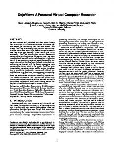
Fig. 1. Cross-layer architecture for signaling communication between interface buffer and OPS network.
An optical packet buffer architecture has been previously presented [3], [4]. Furthermore, the architecture’s flexibility and reconfigurability with respect to network congestion control has been shown via the demonstration of active queue management [5], [6]. Here, the basic buffer architecture has been adapted to realize the functionality of packet injection control at the interface of an implemented OPS network. The OPS network test-bed utilizes the SPINet architecture [7], a switching fabric comprising of 2 2 photonic switching nodes arranged in the Omega topology. Optical messages are switched using semiconductor optical amplifiers (SOAs), yielding wideband transmission, data transparency, and packet-rate granularity. SPINet does not employ optical buffering within its switching nodes, thus messages are dropped upon contention. A physical layer acknowledgement protocol allows for a drop-detection mechanism in which an optical acknowledgement (ack) pulse is sent from the receiving port upon successful transmission. Retransmission can then occur with minimal latency and reduced penalty due to dropped messages. In this letter, the interoperability between the implemented network interface packet buffer and a 4 4 SPINet OPS network test-bed is experimentally demonstrated [8]. The interface buffer actively queues packets prior to injection into the network (Fig. 1). The SPINet ack pulses are further leveraged to provide cross-layer signaling at the buffer-network interface, thus mitigating unsuccessful transmissions through the network. The buffer discards its copies of correctly routed packets, while dynamically retransmitting packets dropped due to contention within the network. High bandwidth optical packets containing 6 10 Gb/s wavelength-striped payloads are transparently processed at the interface buffer and correctly routed through the OPS network.
1041-1135/$25.00 © 2008 IEEE
968
IEEE PHOTONICS TECHNOLOGY LETTERS, VOL. 20, NO. 12, JUNE 15, 2008
the output. In this way, the physical layer ack pulse is leveraged as a means of feedback cross-layer signaling between the interface buffer and the network. To provide immediate egression for serially acknowledged packets, the buffer architecture provides an additional output packet pathway from the first module. III. EXPERIMENTAL DEMONSTRATION A. Experimental Setup
2
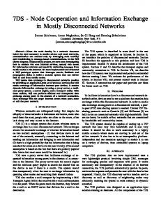
Fig. 2. (a) Buffer architecture with 3 3 SOA switches; FIFO functionality is shown, numbers correspond to the relative age of the packets (1 is oldest, 5 is newest); dotted lines depict the electronic control read/write signals. (b) Implemented two-module buffer with SPINet test-bed.
II. OPTICAL BUFFER ARCHITECTURE A. Basic Architecture The basic optical packet buffer architecture is composed of identical building-block modules organized in a cascaded hierarchical structure [Fig. 2(a)]. Each module uses a 3 3 SOA-based switch and can buffer a single packet of fixed length in a fiber delay line (FDL). In a time-slotted fashion, packets of fixed length enter the buffer via the root module. If the buffer is empty, the packets are stored in the root’s FDL; otherwise, packets are propagated upward along the cascade until an unoccupied module is encountered. In a typical implementation, first-in first-out (FIFO) ordering ensures the age of a given packet corresponds to its position in the cascade [Fig. 2(a)]. Further, reading packets from the buffer are independent of the write process. An electronic read signal is transmitted to the root module, which subsequently forwards the contents of its FDL to the output. The read signal is then regenerated and retransmitted through the cascade, advancing the stored packets incrementally towards the root. Each module is a self-sufficient unit requiring no central management. Increased buffer capacity is realized by connecting additional modules to the end of the cascade. B. Buffer Functionality In order to implement the network interface buffer, the basic architecture was modified via the programmable modules to offer interoperability with the SPINet OPS network [Fig. 2(b)]. The adapted buffer stores and transmits the oldest unacknowledged packet at each timeslot until an optical acknowledgement pulse is sent by the network. Once a packet is successfully transmitted to the output port, an ack is sent to the buffer. The Ack Translator produces an electronic ack in, which is received within the same timeslot, replacing the read signals in the prototypical design. Upon reception of an ack, the currently transmitting packet is discarded from the queue in the following timeslot and the next packet in the buffer is injected into the network. If a packet is dropped due to contention, the buffer will dynamically retransmit the packet until it is successfully transmitted to
To demonstrate the interoperability of the network interface buffer with the OPS test-bed, optical packets are first injected into the buffer and are subsequently stored in the buffer’s queue until successful network transmission occurs. The system’s broadband transparency is illustrated through a wavelength-striped packet format. Control information (framing and address) is encoded on dedicated wavelengths, while the payload is segmented and modulated at 10 Gb/s on six additional wavelengths across the ITU -band. The switching node is transparent to the multiwavelength payload format, with all wavelengths propagating together. A two-module experimental prototype of the interface buffer [Fig. 2(b)] is built for the demonstration. The decision logic is synthesized in a Xilinx complex programmable logic device (CPLD), with two distinct versions of the logic truth table: one pertaining to the root module and another for subsequent, higher order modules; this is owing to the necessarily asymmetric behavior of the root module with respect to the higher order modules. Each building-block module is comprised of commercially available components: the aforementioned CPLD, five SOAs operating as switching elements, and two 155 Mb/s p-i-n photodetectors; no optical filters are necessary in this implementation. The 4 4 experimental network test-bed [Fig. 2(b)] is comprised of four 2 2 switching nodes, also realized with discrete components. The network switching nodes decode control information by filtering the two header bits (frame and address). Using the control information, the CPLD then gates the node’s four SOAs to appropriately route the packets. The systems leverage SOAs as the switching elements, allowing for the compensation of insertion losses arising from the passive coupling elements internal to each node. In this way, each SOA hop contributes no net gain or loss, and packet longevity is maintained. For the interface buffer implementation, an additional SOA is required at the output of the second module; this SOA acts as a simple amplifier for the purpose of gain equalization between the root and first buffer modules. The implemented system supports 128-ns timeslots, containing 115.2-ns duration packets modulated with 10-Gb/s data on six payload wavelengths. The packets are modulated by a single LiNbO modulator with a pseudorandom bit sequence at 10 Gb/s in nonreturn-to-zero format. Cross-layer signaling ack pulses are generated by an Agilent ParBERT to inject packets from the buffer. B. Results Fig. 3(a) depicts the experimental optical packet sequence; Fig. 3(b) shows the input and output waveforms for packets emerging from the integrated buffer-network operation. All packets from the network are correctly routed. Packet A is first stored in the buffer and is simultaneously injected into
LAI et al.: CROSS-LAYER COMMUNICATION WITH AN OPS NETWORK VIA A MESSAGE INJECTION CONTROL INTERFACE
969
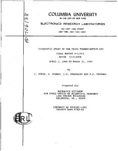
Fig. 5. 10-Gb/s sensitivity curves for Packet C (experiencing six SOA hops).
Fig. 3. (a) Diagram depicting experimental packet sequence. Contention occurs between Packets B and D; thus, B is retransmitted at a later timeslot. (b) Optical waveforms for the buffer and network input and output signals.
Fig. 4. 10-Gb/s input (left) and output (right) optical eye diagrams of C.
the network; it is successfully transmitted and thus discarded from the buffer. Two timeslots later, B is similarly injected into the buffer and network. Simultaneously, another network port injects D, causing contention between B and D. In this case, D is received at the network output, while Packet B is dropped. Consequently, the buffer does not receive an ack and then reinjects its stored copy of B. Packet C also appears at the buffer input and thus is stored in the buffer. The second transmission of B is successful and, in accordance with FIFO ordering, C is injected into the network in the following timeslot and is successfully transmitted to the network output. Fig. 4 portrays the input and output eye diagrams for one 10-Gb/s payload wavelength (1558.31 nm) for C, which undergoes six SOA hops, the greatest number of SOAs experienced by any packet. The packet is amplified at the network output with an erbium-doped fiber amplifier, filtered, and received by a p-i-n photodiode integrated with transimpedance amplifier and limiting amplifier pair. The received electronic signals are then transmitted to a bit-error-rate tester (BERT) that is synchronized with the packet gating signal. The modulating bit pattern is driven by a pulse pattern generator. Bit-error-rate (BER) measurements show packets are received from the output error-free
on all six payload wavelengths. To with BERs less than further support the system’s enhanced operation, Fig. 5 presents BER curves at 10 Gb/s for Packet C. No error floor is observed as 3.5 dB, and the power penalty is evaluated at BER indicating a power penalty of 0.6 dB per SOA hop. IV. CONCLUSION The feasibility and functionality of cross-layer communication is demonstrated via the joint operation of an injection control buffer with an OPS network. Multiple wavelength optical packets are transparently processed by the interface buffer and dynamically rerouted through the network. Wavelength-striped optical packets with 6 10 Gb/s payloads are routed, with errorfree transmission on all payload wavelengths BER . This exploration exemplifies the potential for enhanced network performance through the dynamic interoperability between an optical packet injection control buffer and an OPS network. REFERENCES [1] R. Ramaswami and K. N. Sivarajan, Optical Networks-A Practical Perspective, 2nd ed. San Francisco, CA: Morgan Kaufmann, 2002, ch. 12. [2] M. Enachescu, Y. Ganjali, A. Goel, N. McKeown, and T. Roughgarden, “Routers with very small buffers,” SIGCOMM Comput. Commun. Rev., vol. 35, no. 3, pp. 83–90, Jul. 2005. [3] B. A. Small, A. Shacham, and K. Bergman, “A modular, scalable, extensible, and transparent optical packet buffer,” J. Lightw. Technol., vol. 25, no. 4, pp. 978–985, Apr. 2007. [4] A. Shacham, B. A. Small, and K. Bergman, “A novel optical buffer architecture for optical packet switching routers,” in Eur. Conf. Opt. Commun. (ECOC 2006), Cannes, France, Sep. 2006, Paper We1.4.4.A. [5] A. Shacham and K. Bergman, “Optical packet buffers with active queue management,” in Int. Conf. Opt. Networking Design Modeling (ONDM 2007), Athens, Greece, May 2007, Paper Th2.1. [6] H. Wang, C. P. Lai, A. Shacham, and K. Bergman, “Experimental demonstration of network congestion control with a programmable optical packet injection buffer,” in Proc. Annu. IEEE Lasers & ElectroOptics Soc. (LEOS 2007), Lake Buena Vista, FL, Oct. 2007, Paper ThG2. [7] A. Shacham, H. Wang, and K. Bergman, “Experimental demonstration of a complete spinet optical packet switched interconnection network,” in Opt. Fiber Commun. Conf. (OFC 2007), Anaheim, CA, Mar. 2007, Paper OThF7. [8] C. P. Lai, H. Wang, and K. Bergman, “Interface optical buffer and packet-switched network cross-layer signaling demonstration,” in Opt. Fiber Commun. Conf. (OFC 2008), San Diego, CA, Feb. 2008, Paper OThI5.