Current Issues in Multi-Paradigm Modeling Juan de Lara1 , Tiham´er Levendovszky2 , Pieter J. Mosterman3 , Hans Vangheluwe4 1
2
Universidad Aut´ onoma de Madrid, Spain.
[email protected] Budapest Univ. of Technology and Economics, Hungary.
[email protected] 3 The MathWorks, Inc.
[email protected] 4 McGill University (Montr´eal), Canada.
[email protected]
Abstract. The comprehensive use of models in design has created a set of challenges beyond that of supporting one isolated design task. In particular, the need to combine, couple, and integrate models at different levels of abstraction and in different formalisms is posing a set of specific problems that the field of Computer Automated Multiparadigm Modeling (CAMPaM) is aiming to address. This paper summarizes the results of the 2nd Workshop on Multi-Paradigm Modeling: Concepts and Tools.
1
Introduction
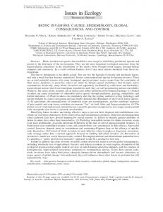
Computational modeling has become the norm in industry to remain competitive and be successful [23]. As such, Model-Based Design of, for example, embedded software has enterprise-wise implications and modeling is not limited to isolated uses by a single engineer or team. Instead, it has reached a proliferation much akin to large software design, with requirements for infrastructure support such as version control, configuration management, automated processing, etc. The comprehensive use of models in design has created a set of challenges beyond that of supporting one isolated design task. In particular, the need to combine, couple, and integrate models at different levels of abstraction and in different formalisms is posing a set of specific problems that the field of Computer Automated Multi-paradigm Modeling (CAMPaM) is aiming to address [16, 22]. The essential element of multi-paradigm modeling is the use of explicit models throughout. This leads to a framework with models to represent the syntax of formalisms used for modeling, models of the transformations that represent the operational semantics, as well as model-to-model transformations for interformalism transformation [12]. These models are then used to facilitate generative tasks in a language engineering, such as evolving a domain-specific modeling formalism as its requirements change, but also in a tool engineering space, such as automatic generation of integrated development environments. Moreover, an explicit model of a model transformation allows analyses such as termination characteristics, consistency, and determinism [4]. Thus, CAMPaM addresses two orthogonal problem directions: 1. Multi-Formalism Modeling [21], concerned with the coupling of, and transformation between, models described in different formalisms. In Figure 1, a
2
part of the “formalism space” is depicted in the form of a formalism transformation graph (FTG). The different formalisms are shown as nodes in the graph. The arrows denote a homomorphic relationship “can be mapped onto”. The mapping consists of transforming a model in the source formalism into one in the target formalism preserving certain pertinent properties.
PDE Bond Graph a-causal KTG
Cellular Automata DAE non-causal set Process Interaction Discrete Event Bond Graph causal
System Dynamics
Statecharts
DAE causal set
Petri Nets 3 Phase Approach Discrete Event
Transfer Function
DAE causal sequence (sorted)
Activity Scanning Discrete Event Event Scheduling Discrete Event
Timed Automata
scheduling-hybrid-DAE DEVS&DESS Difference Equations
DEVS
state trajectory data (observation frame)
Fig. 1. The Formalism Transformation Graph (FTG).
The specification of a composite system may include the coupling of heterogeneous components expressed in different formalisms. For the analysis of its properties the composite system must be assessed by looking at the whole multi-formalism system. Components may have to be transformed to a common formalism, which can be found in the FTG [21]. Formalisms can be meta-modelled and the transformations denoted by the arrows of the FTG can be modelled as model transformations. In contrast, in the co-simulation approach [6], each component is simulated with a formalism-specific simulator. Interaction because of component coupling is resolved at the trajectory (simulation data) level. Questions about the overall system can only be answered at the level of input/output (state trajectory). It is no longer possible to answer symbolic, higher-level questions which could be answered within the formalisms of the individual components. 2. Model Abstraction, concerned with the relationship between models at different levels of abstraction. Models described in either the same or in different formalisms can be related through the abstraction relationship, and its dual, refinement. A foundation for the notion of abstraction, is the information contained in a model M , defined as the different questions (properties) P = I(M ) which can be asked concerning the model (|P | and p, p0 ∈ P : p 6= p0 ). These questions either result in true or false (M |= p or M 6|= p).
3
A relation between two models M1 and M2 can have the character of an abstraction, refinement, or equivalence relative to a non empty set of questions (properties) P . – In case of an equivalence, it is required that for all p ∈ P holds: M1 |= p ⇐⇒ M2 |= p. This is written M1 =P M2 . – If M1 is an abstraction of M2 with respect to P it holds for all p ∈ P holds: M1 |= p ⇒ M2 |= p. This is written M1 wP M2 . – Furthermore, M1 is said to be a refinement of M2 iff M1 is an abstraction of M2 . This is written M1 vP M2 . Further discussion of this is included in the summary of the 1st Workshop on Multi-Paradigm Modeling: Concepts and Tools in 2006 [7]. To address the problems from the use of multiple formalisms and multiple levels of abstraction, meta-modeling and model transformation are used. MetaModeling [23] is based on the explicit modeling of modeling formalisms. Formalisms are described as models using meta-formalisms that are expressive enough to describe other formalisms’ syntax and semantics. Examples are the Entity Relationship formalism and UML class diagrams. Model transformation is based on the explicit modeling of model transformations.
2
The Workshop
The objective of the workshop was to provide a forum to discuss the concepts as well as the tool building aspects required for multi-paradigm modeling. It was oriented to researchers and practitioners working in the modeling, simulation and analysis of complex systems, dealing with multiple paradigms in a modeldriven manner. This includes tool vendors, academic researchers which address tool building as well as users of these tools. This year workshop included five research paper presentations and one invited talk by Gabor Karsai (ISIS/Vanderbilt University) entitled “Multi-paradigm Modeling: Some past projects, lessons learned, and research challenges”. The presentation addressed how the model-based engineering of large-scale embedded information systems often necessitates the use of different, heterogeneous modeling paradigms. Multiple-aspect, multi-paradigm, domain-specific models capture not only the physical and functional views of the hardware and the software architecture, but they should also represent interactions among different physical domains, as well as non-functional aspects like faults and their effects, safety properties, and many others. The presentation highlighted the experience from four different projects in last fifteen years, where multi-paradigm modeling had to be used to solve complex design and operational problems. Various examples were given for the modeling paradigms used in specific engineering systems. The research issues discussed included the problems of interacting engineering domains, the integration of models and their modeling languages, and the semantics of modeling paradigms and their precise specification. The papers were presented in two sessions, both chaired by Pieter Mosterman. The first session was entitled MPM Concepts and Applications and included three papers:
4
– “ModHel’X: A Component-Oriented Approach to Multi-Formalism Modeling”, by C. Hardebolle and F. Boulange [9]. In this paper, the authors address two important issues: to provide support for the specification of the semantics of a modeling formalism, and to allow the specification of the interactions between parts of a model described using different modeling formalisms. For this purpose, they present the ModHel’X system, which focuses on model execution, including simulation, code generation and real-time execution. – “From UML State Charts to DEVS State Machines using XML”, by J.L. Risco-Mart´ın, S. Mittal, B. Zeigler and J.M. de la Cruz [18]. In this contribution, the authors present an integrated approach towards using UML state machines transformed as DEVS [24] models. The transformation mechanism is available as an upcoming standard, State Chart XML (SCXML) that provides a generic execution environment based on CCXML and Harel State tables. The transformation is ilustrated by taking a UML state machine and augmenting it with information during the process using SCXML to make it DEVS capable. The obtained DEVS models are indeed Finite Deterministic DEVS, able to be encoded as a W3C XML schema. – “Applying Multi-Paradigm Modeling to Multi-Platform Mobile Development”, by L. Lengyel, T. Levendovszky and C. Hassan [14]. In this work, the authors introduce some CAMPaM ideas in their meta-modeling and model transformation framework, the Visual Modeling and Transformation System (VMTS). The concepts are illustrated with an example in model-based development for mobile platforms. The second session was entitled MPM Tools, and included two papers: – “Towards Parallel Model Transformations”, by G. Mezei, H. Charaf, T. Levendovszky [15]. In this contribution, the authors tackle the problem of efficiency of graph transformation by proposing the execution of model transformations in parallel. The paper presents algorithms to find and apply steps of the transformations in parallel, and an implementation is given the Visual Modeling and Transformation System (VMTS). – “Domain-specific Model Editors with Model Completion”, by S. Sen, B. Baudry and H. Vangheluwe [20]. In this paper, the authors propose an integrated software system capable of generating recommendations for model completion of partial models built in arbitrary domain-specific model editors. The automatic completion is powered by a Prolog engine whose input is a constraint logic program derived from the specification (meta-model with constraints) of the modeling language to which the partial models belong.
3
Working Group Results
The workshop included two working group discussion sessions. 3.1
Consistency
This working group consisted of K. Cerans, B. Latronico, D. Matheson, E. Syriani, and H. Vangheluwe. The discussion focused on model consistency.
5
In the development of complex systems, multiple views on the system-to-bebuilt are often used. These views typically consist of models in different formalisms. Different views usually pertain to various partial aspects of the overall system. In a multi-view approach, individual views are (mostly) less complex than a single model describing all aspects of the system. As such, multi-view modeling, like modular, hierarchical modeling, simplifies model development. Most importantly, it becomes possible for individual experts on different aspects of a design to work in isolation on individual, possibly domain-specific views without being encumbered with other aspects. These individual experts can work mostly independently, thereby considerably speeding up the development process. This approach does however have a cost associated with it. As individual view models evolve, inconsistencies between different views are often introduced and those need to be corrected. Ensuring consistency between different views requires periodic concerted efforts from the model designers involved. In general, the detection of inconsistencies and recovering from them is a tedious, error-prone and manual process. Automated techniques can alleviate the problem and this has been investigated in the Concurrent Engineering community over the last two decades [2]. These solutions were often based on some form of constraint propagation between the different views. Al-Anzi and Spooner [1] give a classification of inconsistencies that may occur in the context of Concurrent Engineering. Easterbrook et. al [3] introduce the notion of ViewPoints and describe how consistency between them can be checked. In the Software Engineering community, the consistency between different views of a design has also been studied extensively [5, 8]. For the sake of the discussions, a working definition of consistency was proposed: A set of models M is consistent with respect to a set of consistency constraints C over M if all constraints in C are satisfied. M is inconsistent when at least one of the constraints in C is not satisfied. Consistency constraints may pertain to syntax as well as to semantics of models. In the former case, the constraints may pertain to the structure of models or to values of model attributes. In the case of semantics, the consistency constraints are defined over the semantic domain. This implies that models may have to be simulated to check consistency. Whereas checking consistency constraints over a set of models can be done in isolation, often one starts from a consistent set of models and then incrementally makes changes to some of the models (usually one at a time). In this case, inconsistencies should be detected and where possible, modifications to (other) models in M must be made to maintain consistency. As such, changes in one model are propagated to other models. Which changes need to be made is determined by the consistency constraints. It is noted that a consistency check of a set of models in isolation can sometimes be performed by incrementally constructing the set from an empty set, keeping consistency at each intermediate step. Triple Graph Grammars (TGGs) [19] were proposed as a reasonable starting point for automating consistency checking and enforcement, at least at a structural level (and initially, only for two models). In TGGs, two meta-model
6
graphs are connected via a correspondence graph. This declarative model allows for checking consistency of the models, both with the meta-models and with each other. Furthermore, a collection of unidirectional change propagation rules can be inferred from the TGG model [10]. Related work has demonstrated this and has shown how conflict situations can be detected [11]. Furthermore, potential rules to resolve a conflict can be presented to the user for manual intervention. At the level of attribute relationships, a declarative specification would be desirable and Modelica (www.modelica.org) was suggested as a starting point. 3.2
Simulation
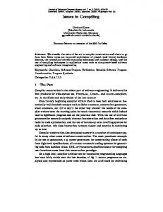
This working group consisted of C. Hardebolle, T. Levendovszky, P.J. Mosterman, and J.L. Risco-Mart´ın. The discussion focused on models of time for the execution of models that are designed using different formalisms. A concrete application example is formed by the networked power window control system that is sketched in Fig. 2. In the example a bus, depicted by a double straight line at the bottom, connects three controllers; a window controller, a lights controller, and a mirror controller. These three controllers may be implemented by different microcontrollers. To connect the controllers to the physical part of the system, actuators and sensors are employed. This is illustrated for the power window system where the controller actuates the window by a dc motor and obtains feedback measurements from a current sensor [17].
window
dc motor
current sensor window controller
lights controller
mirror controller
Fig. 2. A networked power window control system.
In the design of such a networked embedded system, a number of different formalisms are routinely employed. For example, the physics of the window movement includes the dynamics because of the window mass, the lift mechanism, and friction coefficients, and may be best modeled using differential equations, either as a system of ordinary differential equations (ODE) or as a system of differential and algebraic equations (DAE). This is schematically presented in Fig. 3(a), which shows a behavior that varies continuously with respect to time. The behavior of the controller, on the other hand, often is implemented as periodic using a given sample time to determine the period. The controller may
7
t (a) Continuous time.
t (b) Discrete time.
t (c) Discrete event.
Fig. 3. State trajectories.
implement a number of tasks that may execute with different periods. This is illustrated in Fig. 3(b), where the sample time is represented by the distance in time between the dashed lines. Two tasks are shown, one at the bottom with a period of two and one at the top with a period of three. The window controller may obtain its setpoint commands (i.e., whether to move the window up, down, or not at all) from a user operated switch that is located elsewhere in the vehicle. The commands are then communicated over a network that is also utilized by other control systems. To study the effects of the network and to determine the quality of service, the events at which data is transferred across the network are modeled. This is depicted in Fig. 3(c) by events that occur at points in time that may be arbitrarily spaced. This illustrates how over certain intervals of time, the event density may be high, whereas at other times the event density may be low. The discussion centered around three different types of temporal semantics of models – continuous-time, x(t) ˙ = f (x(t), u(t), t(t)) – discrete-time, x(tk + h) = f (x(tk ), u(tk ), tk ) – discrete-event, x(tk + hk ) = f (x(tk ), u(tk ), tk ) This classification has been discussed in detail by Zeigler, Kim, and Praehofer [24] The working group concentrated specifically on the efficient generation of behaviors of the separate computational systems in isolation and in combination. Continuous-time systems are typically executed by discretizing the continuous trajectory by using a numerical integration routine, embodied by a solver. The discretized points in time are indicated in Fig. 3(a) by the circles along the continuous trace. To efficiently execute an ODE, a specific solver has to be selected based on the characteristics of the behavior that the ODE embodies. Discrete-time systems that represent embedded control can often be executed based on a static schedule, for example derived to be rate-monotonic. This results in little overhead in determining when a period starts (e.g., by doing an integer comparison) but the sample time that is employed may result in scheduled points in time at which no changes in the system occur. This is illustrated in Fig. 3(b) by the first sample hit where no change in either of the two tasks occurs. To avoid such superfluous sample time hits, an event calendar can be implemented which allows very efficient handling of variable event densities such as in discrete event systems. In Fig. 3(c) it is illustrated how for a discrete event system values in between two events may be considered irrelevant. This in contrast
8
with the zero-order hold that is typically applied in discrete-time systems. The event calendar to handle such variable event density consists of a data structure that has to very efficiently order new events based on their future time of occurrence. Similarly, scheduled events that are retracted have to be found with low time complexity. This leads to three different types of execution engines, each with their respective benefits and drawbacks. Where a continuous-time execution engine can efficiently determine the step size based on differential equations, the integration mechanism is overly complex for determining the sample time hits in a discrete time system. A static schedule is more efficient, even in the face of superfluous sample time hits. However, in case of discrete-event systems, the sample time would have to be chosen arbitrarily small, which would result in excessive superfluous events whilst still resulting in error in the exact event time. While for discrete-event systems an event calendar is more efficient, such a heavy-weight data structure is excessively complex for executing a discrete-time system. Likewise, the static scheduling as implemented for discrete-time systems is often not applicable for continuous-time simulation as it would result in a fixed time-step of the numerical integration. A notable exception is real-time simulation where such a fixed time-step is a necessity. The discussion then was directed towards potential solutions to obtain the best of each of the separate execution technologies without arriving at a conclusive assessment of the best approach.
4
Workshop Participants
Tihamer Levendovszky Budapest University of Technology and Economics, Hungary Eugene Syriani McGill University, Canada Hans Vangheluwe McGill University, Canada Janis Barzdins University of Latvia, Latvia Ryan Thibodeaux Vanderbilt University, USA Dan Matheson Integware, USA Jose L. Risco-Martin Universidad Complutense Madrid, Spain Pieter van Gorp Antwerp University, Belgium ´ ´ ´rieure d’Electricit ´, France Cecile Hardebolle Ecole Supe e Sumant Tambe Vanderbilt University, USA Akshay Dabholkar Vanderbilt University, USA Jon Oldevik SINTEF, Norway Karlis Cerans University of Latvia, Latvia Pieter J. Mosterman The MathWorks, Inc., USA Thomas Kuehne Victoria University of Wellington, New Zealand Joanna Chimiak-Opoka University of Innsbruck, Austria Beth Latronico Bosch, USA
9
5
Program Committee
Peter Bunus Link¨ oping University Michel Chaudron Eindhoven University of Technology Jean-Marie Favre University of Grenoble Holger Giese Universit¨ at Paderborn Mirko Conrad The MathWorks, Inc. David Hill Blaise Pascal University Jozef Hooman Embedded Systems Institute Gabor Karsai Vanderbilt University Thomas Ku ¨ hne Victoria University of Wellington, New Zealand Klaus Mu ¨ ller-Glaser University of Karlsruhe Hessam S. Sarjoughian Arizona State University Mamadou K. Traor´ e Blaise Pascal University Jeroen Voeten Eindhoven University of Technology Hans Vangheluwe McGill University 5.1
External Reviewers
Ernesto Posse McGill University Philipp Graff University of Karlsruhe
6
Acknowledgements
The activities described in this paper supported, in part, by the Information Technology Innovation and Knowledge Centre. This paper was supported by the J´anos Bolyai Research Scholarship of the Hungarian Academy of Sciences, and the Spanish Ministry of Science and Education, project MOSAIC (TSI200508225-C07-06). The Canadian National Sciences and Engineering Research Council (NSERC) and the Canadian research network MITACS are gratefully acknowledged for their support.
References 1. Al-Anzi, F.S., Spooner, D.L. 1996. Classification and consistency of behavior in complex object design views for concurrent engineering. Proc. Int. Conf. on Data and Knowledge Systems for Manufacturing and Engineering, IEEE Comp. Soc. Press. 2. Dewan, P., Riedl, J. 1993. Toward computer-supported concurrent software engineering. IEEE Computer 26 pp.: 17–27 3. Easterbrook, S., Finkelstein, A., Kramer, J., Nuseibeh, B. 1994. Coordinating distributed viewpoints: The anatomy of a consistency check. Int. Journal on Concurrent Engineering: Research & Applications 2, pp.: 209–222 4. Ehrig, H., Ehrig, K., Prange, U., Taentzer, G. 2006. Fundamentals of Algebraic Graph Transformation. Springer.
10 5. Finkelstein, A., Gabbay, D., Hunter, A., Kramer, J., Nuseibeh, B. 1994. Inconsistency handling in multiperspective specifications. IEEE Transactions on Software Engineering 20, pp.: 569–578. 6. Fishwick, P., Zeigler, B. P. 1992. A Multimodel Methodology for Qualitative Model Engineering. ACM Transactions on Modelling and Computer Simulation 1(2), 52-81. 7. Giese, H., Levendovszky, T., Vangheluwe, H. 2007. Summary of the Workshop on Multi-Paradigm Modeling: Concepts and Tools. Models in Software Engineering, pp.: 252-262. 8. Grundy, J., Hosking, J., Mugridge, W.B. 1998. Inconsistency management for multiple-view software development environments. IEEE Transactions on Software Engineering 24, pp.: 960–981. 9. Hardebolle, C., Boulanger, F. 2007. ModHel’X: A Component-Oriented Approach to Multi-Formalism Modeling, in [13], pp.: 49–60. 10. K¨ onigs, A. 2005. Model Transformation with Triple Graph Grammars. Model Transformations in Practice Satellite Workshop of MODELS’05, Montego Bay, Jamaica. 11. K¨ onigs, A., Sch¨ urr, A. 2006. Tool Integration with Triple Graph Grammars - A Survey. Vol. 148 of Elec. Notes in Theo. Comp. Science, Elsevier, pp.: 113–150. 12. de Lara, J., Vangheluwe, H. 2004. Defining visual notations and their manipulation through meta-modelling and graph transformation. J. Vis. Lang. Comput. 15(3-4):309–330. Elsevier. 13. de Lara, J., Levendovszky, T., Mosterman, P. J. 2007. Proc. of the Workshop on Multi-Paradigm Modeling: Concepts and Tools. BME-DAAI Tech. Rep. Series Vol. 1. Budapest Univ. of Tech. and Economics Dep. Automation and Applied Informatics. 14. Lengyel, L., Levendovszky, T., Hassan, C. 2007. Applying Multi-Paradigm Modeling to Multi-Platform Mobile Development, in [13], pp.: 9–22. 15. Mezei, G., Charaf, H., Levendovszky, T. 2007. Towards Parallel Model Transformations, in [13], pp.: 23–34. 16. Mosterman, P. J., Vangheluwe, H. 2002. Guest Editorial: Special issue on computer automated multi-paradigm modeling. ACM TOMACS 12(4), pp.: 249–255. 17. Mosterman P. J., Sztipanovits, J., Engell, S. 2004. Computer Automated MultiParadigm Modeling in Control Systems Technology. IEEE Transactions on Control System Technology, 12(2), pp.: 223–234. 18. Risco-Mart´ın, J. L., Mittal, S., Zeigler, B., de la Cruz, J. M. 2007. From UML State Charts to DEVS State Machines using XML, in [13], pp.: 35–48. 19. Sch¨ urr, A. 1994. Specification of Graph Translators with Triple Graph Grammars. Proc. WG’94, LNCS 903, pp.: 151–163, Springer. 20. Sen, S., Baudry, B., Vangheluwe, H. 2007. Domain-specific Model Editors with Model Completion., in [13], pp.: 61–74. 21. Vangheluwe, H. 2000. DEVS as a common denominator for multi-formalism hybrid systems modelling. In IEEE Int. Symposium on Computer-Aided Control System Design, Anchorage, Alaska. pp.:129–134. IEEE Computer Society Press. 22. Vangheluwe, H., de Lara, J., Mosterman, P. J., 2002. An Introduction to MultiParadigm Modelling and Simulation, Proc. AI Simulation&Planning, pp.: 9-20. olter, M., Stahl T. 2006. Model-Driven Software Development. Willey. 23. V¨ 24. Zeigler, B., Kim, T., Praehofer, H. 2000. Theory of Modeling and Simulation: Integrating Discrete Event and Continuous Complex Dynamic Systems, Academic Press.