CYCLIC TESTING OF DUCTILE END DIAPHRAGMS SLAB-ON-GIRDER STEEL BRIDGES
FOR
By Seyed Mehdi Zahrai1 and Michel Bruneau,2 Member, ASCE ABSTRACT: Ductile end diaphragms have been proposed as seismic retrofit strategy to protect the substructures of existing steel slab-on-girder bridges from damage during earthquakes. This paper presents the results from an experimental program to investigate the adequacy of some proposed details. Cyclic tests on full-size girder specimens having the proposed ductile diaphragms demonstrate that these can possess adequate initial elastic stiffness, strength, and capacity to dissipate hysteretic energy in the intended manner. The specimens developed a rotational capacity of 0.2 rad when energy dissipation devices of the TADAS (Triangular-plate Added Damping And Stiffness) type were used, and link distortion angles of 0.08 to 0.11 rad when eccentrically braced frame and shear panel systems were in place, corresponding to average ductilities of 8 to 10 before failure. Better performance of the eccentrically braced frame system would have been possible had lateral support been provided at the ductile link. However, ductile end diaphragms having bolted connections suffered significant slippage, leading to pinched hysteretic curves. Tests show that welding significantly improves the seismic behavior of these ductile systems. Specimens with nominal channel diaphragms and those without any diaphragm dissipated significantly less hysteretic energy, and suffered bolt rupture, buckling of the web stiffeners, and fracture of the stiffeners welds at large drifts.
INTRODUCTION Damage to abutments, piers, bearings, foundations, and other substructure elements of existing bridges during recent earthquakes (e.g. Northridge and Kobe) has proved to have significant consequences, often leading to span collapses (Astaneh-Asl et al. 1994; Bruneau et al. 1996). Earlier research has demonstrated how substructure damage in slab-on-girder steel bridges can be prevented if the existing end diaphragms over abutments and piers are replaced with specially designed ductile diaphragms calibrated to yield before the strength of the substructure is reached (Zahrai and Bruneau 1999). Interior diaphragms need not be replaced as they do not contribute to the lateral load resistance (Zahrai and Bruneau 1998a). This alternative seismic retrofit strategy has been analytically validated for bridges supported on stiff substructures, and shown to be inappropriate in the presence of flexible substructures. Although its success relies on energy-dissipating devices previously used in building applications, experimental work is needed to prove their effectiveness and establish appropriate details within the proposed ductile bridge diaphragms. To that end, a series of cyclic tests were carried out on fullscale specimens, each having a ductile end diaphragm introduced between two short segments of main girders. The results of this experimental work are reported in this paper, along with practical recommendations. EXPERIMENTAL APPROACH Design of Test Specimens Prior research (Zahrai and Bruneau 1998a) on the lateral load resistance and deflected shape of steel slab-on-girder bridges has demonstrated that only the end diaphragms and the girder segments having bearing stiffeners and located near 1 Postdoctoral Fellow, Build. Perf. Lab., M24 Build., Nat. Res. Council Canada, 1500 Montreal Rd., Ottawa, ON, Canada K1A 0R6. E-mail: seyed.
[email protected] 2 Prof., Dept. of Civ., Struct., and Envir. Engrg., State Univ. of New York at Buffalo, 130 Ketter Hall, Buffalo, NY 14260. E-mail: bruneau @acsu.buffalo.edu Note. Associate Editor: Brad Cross. Discussion open until February 1, 2000. To extend the closing date one month, a written request must be filed with the ASCE Manager of Journals. The manuscript for this paper was submitted for review and possible publication on December 7, 1998. This paper is part of the Journal of Structural Engineering, Vol. 125, No. 9, September, 1999. 䉷ASCE, ISSN 0733-9445/99/0009-0987–0996/ $8.00 ⫹ $.50 per page. Paper No. 19767.
the supports effectively contribute to the total lateral load resistance (unless numerous tightly spaced intermediate web stiffeners are present). For that reason, a short girder segment that includes the diaphragm and bearing stiffeners can effectively capture the lateral response behavior of slab-on-girder bridges. Specimens considered here were designed accordingly. Furthermore, because more practical energy-dissipating device sizes are obtained when only one ductile diaphragm is located at each bridge end, only two girders connected by a ductile diaphragm needed to be considered in this test program. As such, specimens representative of existing 40 m span steel slab-on-girder bridges were achieved by using two 0.5 m long segments of WWF1200⫻333 girders, 2 m center to center, and having 10 mm thick and 100 mm wide bearing web stiffeners on each side of the web. A 200 mm thick reinforcement concrete deck, connected to the top flange of each girder segment by 10 shear studs, was poured in place during construction of the specimens. These girders were then joined by the same three types of ductile end-diaphragm systems considered in the prior analytical study (Zahrai and Bruneau 1999), namely triangular-plate added damping and stiffness device (TADAS), eccentrically braced frame (EBF) diaphragms, and a shear panel system (SPS). All three shared a chevron braced frame configuration—with a bottom beam— and two double angles as diagonal braces. In designing the specimens, design details and recommendations developed by other researchers for the special ductile devices integrated in these diaphragms were followed. The systems were also sized following the retrofit design procedure presented elsewhere (Zahrai and Bruneau 1999), considering that the entire bridge (with four girders) should be able to resist a design peak ground acceleration of approximately 0.5g. The resulting generalized tributary mass of 71,500 kg at each bridge end induced an elastic lateral load of 1325 kN. According to the code recommendations (LRFD 1994; Handbook 1995), a reduction factor, R, of 3.75 was considered corresponding to ductility ratio, , of 7.5 in accordance with Newmark-Hall’s procedure for short-period structures (Newmark and Hall 1982). This gave an inelastic seismic force of 350 kN for each specimen to be considered for design of the ductile devices. Note that, in this design, each girder was assumed to be fully fixed at its top and base, to better represent the experimental conditions. Although fixity condition at fixed or expansion bearings approaches that of a hinge in most field conditions, specimens in this experimental JOURNAL OF STRUCTURAL ENGINEERING / SEPTEMBER 1999 / 987
program were provided with full fixity at both ends to investigate whether the ductile diaphragm system works considering the most detrimental fixity condition; girders that are stiffer laterally can resist a significant portion of the lateral load, which complicates the retrofit design procedure and could result in undesirable damage in the bearing stiffeners. From the above design procedure, the TADAS device was designed with four 25 mm thick triangular plates having a height and a base width of 105 and 80 mm, respectively, and providing a device stiffness and a strength of 150 kN/mm and 167 kN, respectively. The base of the TADAS plate assembly was bolted to the bottom beam. The EBF link length was chosen to be 300 mm, providing a shear yield capacity of 124 kN, which translated into a diaphragm shear strength of 235 kN. Two different SPS designs were considered. First, a W200⫻15 shear link (SPS1) welded directly to the top flange of the bottom beam was considered. Second, a 175 mm long link section (SPS2) was built up using two 130⫻45⫻8 mm plates for each flange, a 175⫻130⫻5 web plate, and one 148⫻45⫻6 horizontal stiffener on each side at midheight, and welded to a 280⫻120⫻10 base plate bolted to the top flange of the bottom beam using eight M20 bolts. Other sizes and details of the surrounding structural elements are illustrated in subsequent figures. CAN/CSA-S16.1-94 Limit State Design of Steel Structures was used to design the components (Handbook 1995). However, braces, bottom beams (outside of the links), and all connections were designed to remain elastic. Note that, in all cases, braces were bolted to a gusset on top of the energy dissipater, as well as to the girder web stiffeners. Furthermore, the above all-bolted diaphragm details were initially chosen to facilitate acceptance by bridge engineers and provide easy replacement of the ductile devices following an earthquake. However, after some testing to large drifts, the EBF specimen was completely welded and retested, as described later. CAN/CSA G40.21-M 350W structural steel (equivalent to ASTM-A572 grade 50) was specified for all the steel specimens. Nominal yield and tensile strengths of 350 and 450 MPa, respectively, were used in designing test specimens. Coupon tests revealed yield strengths of 450, 370, and 450 MPa, respectively, for the EBF, SPS1, and SPS2 specimens, and tensile strengths of 580, 460, and 540 MPa, respectively. The SPS2 coupon failed without necking at 7% elongation,
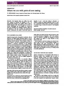
FIG. 1.
even though information on the mill test certificate indicated a material in compliance with the specified steel grade. Coupon tests on web stiffeners revealed yield and tensile strengths of about 400 and 570 MPa, respectively. Test Setup All specimens were subjected to progressively increasing cyclic lateral displacement following as much as possible the ATC-24 protocol (Guidelines 1992). A constant gravity load of 350 kN (i.e., 175 kN per girder), equal to half of the value that would result by integrating the shear stresses along the web of the girders, was applied to the specimens’ deck slabs using two vertical actuators. This equivalent load was selected because it created the same P–⌬ effects on the specimens and actual bridge. The experimental setup is schematically shown in Fig. 1. Three MTS actuators were used to apply the required forces to the specimens: two for gravity loads and one for lateral loads applied in a displacement-control mode. For gravity loads, a load-applicator beam assembly was designed and fabricated. A reaction frame was used to support the end of the horizontal actuator used to apply lateral loads to the specimens. All specimens were instrumented for displacement and strain measurements at the points of interest. They were also whitewashed to help observe the yielding patterns and their progression. Refer to Zahrai and Bruneau (1988b) for more details on the design of the specimens and their instrumentation. Finally, note that two or three different tests were conducted on each of the three sets of bridge girders available for this testing program, as described in the following. Experiments 1, 3, and 6 are those that started with a ‘‘fresh’’ set of girders. Experiment 1 (TADAS End Diaphragm) The TADAS specimen, shown in Fig. 2(a), was subjected to 21 cycles of lateral loading before failure occurred at 4% drift. The final lateral load-deflection curves for the specimen are shown in Fig. 2(b). Note that the hysteretic loops experienced pinching in response to connection slippage and existing gaps ranging from 1 to 2 mm between the top of each TADAS plate and their reaction points at the early stage of loading (these gaps were introduced by the fabricator even though the
Plan and Elevation Schematic Views of Test Setup Prepared for Experiments
988 / JOURNAL OF STRUCTURAL ENGINEERING / SEPTEMBER 1999
drawings called for a perfect fit). Indeed, for loads of 100 kN and above, the load-displacement curve flattened a bit while sharp ‘‘ping’’ noises were heard from slippage of the bolts throughout the diaphragm assembly. Strain gauge data showed that some TADAS plates started to yield at drifts of approximately 1% (variable gap sizes prevented simultaneous yielding), with all TADAS plates yielding when drifts reached 20 and ⫺18 mm (1.5% drift), corresponding to lateral loads of 320 and ⫺350 kN. Fine cracks were observed in the whitewash paint near the top of the TADAS plates. As shown in Fig. 2(c), the TADAS plates bent noticeably during the three cycles at displacements of 25 and ⫺23 mm (2% drift), corresponding to lateral loads of 370 and ⫺380 kN. At that time, the paint on the surface of TADAS plates showed evidence of extensive yielding. The experiment ended after flexural failure of three TADAS plates [Fig. 2(d)] and local buckling of the girder web stiffeners at 4% drift. The maximum positive lateral load applied to the specimen reached 464 kN, corresponding to a maximum drift of 45 mm, while these negative values were ⫺450 kN and ⫺43 mm, respectively. Note that the TADAS device was not provided with lateral bracing, and measured lateral movement (i.e., transverse to the plane of the ductile diaphragm) of less than 1 mm during testing confirms that this was not necessary. Such bracing is, however, recommended for good design practice. Experiment 2 (Stiffened Girders Only) After dismantling all the end-diaphragm members (i.e., TADAS, braces, and bottom beam), the remaining specimen with the two stiffened girders alone was tested to failure. The web stiffeners had cracks propagating from the bolt holes where diaphragms were connected before to the free edge of the stiffeners. In spite of this damage, 25 cycles up to a maximum drift of ⫾96 mm (8%) were applied to the specimen. Fig. 3(a) shows the lateral load versus drift hysteretic curves for this specimen (reader is cautioned that hysteretic curves presented in this paper do not share the same vertical or horizontal axes). Maximum positive and negative lateral load levels reached 165 and ⫺180 kN, respectively. Testing stopped after the specimen experienced severe buckling of the web stiffeners, fracture of all full-penetration welds at the top and bottom of the girder bearing stiffeners, and widening of some of the cracks at the holes of the web stiffeners [Fig. 3(b)]. Experiment 3 (EBF End Diaphragm—EBF1) The EBF end diaphragm tested is shown in Fig. 4(a). Maximum positive and negative lateral loads of 600 kN were imposed to the specimen. As the specimen was loaded up to a 3% drift, a great deal of slip was observed (and heard) in all bolted connections. Fig. 4(b) shows the highly pinched hysteretic curves obtained in the 24 cycles applied to this specimen in the first phase of its testing. Visibly, this extensive slippage was detrimental to the intended ductile performance of the system as larger drifts were required to fully develop yielding within the ductile eccentric link. Consequently, this test was stopped prior to failure of the ductile link or buckling of the girder web stiffeners. The specimen was then recentered, and all bolted connections were welded to provide an opportunity to retest and compare the behavior of an all-welded alternative (EBF2) with the original, mostly bolted detail (EBF1). Fillet welds were used on all available connection surfaces and sized to resist alone the full member capacities (i.e., resistance of the bolts was neglected). FIG. 2. Ductile End-Diaphragm Specimen Having TADAS: (a) Elevation; (b) Hysteretic Curves; (c) Plates under Considerable Flexure at 2% Drift; (d) Close-Up of Device after Experiment
Experiment 4 (EBF with Welded Connections—EBF2) Symmetric and full hysteretic curves were obtained for this all-welded EBF ductile diaphragm as no slippage occurred, in JOURNAL OF STRUCTURAL ENGINEERING / SEPTEMBER 1999 / 989
FIG. 3. First Specimen without Diaphragm: (a) Hysteretic Curves; (b) Fracture of Full Penetration Welds at Bottom of Girder Bearing Stiffeners
contrast to the previous diaphragm test. Yielding of the EBF started at drifts of roughly 5 mm. Large shear distortions of the link became progressively more visible during cycles at 2␦y and 3␦y drift (1% drift). Some strength degradation was observed on the hysteretic curves during cycles at 6␦y (2% drift) as the north side of the east end of the link developed significant visible local buckling [Fig. 4(c)], causing a slight drop in shear resistance. Sideway deflection at the west end of the link increased to 2.8 mm and severe flange distortion ensued. When the specimen was subjected to its 22nd cycle, the first at a displacement of 30 mm (8␦y, or 2.5% drift), the link beam failed because of sudden lateral displacement of the link. As a result of this instability, brittle fracture occurred at the west end of the link flange and buckling developed at the east end of the same flange. Fig. 4(d) shows the hysteretic loops for this experiment, which reached maximum lateral loads of 640 and ⫺650 kN. This failure might have been prevented or delayed had the ends of the link beam been laterally braced (although this was deliberately not done in this case because the short length and lateral stiffness of the bottom beam suggested that this EBF link could reach its target plastic shear distortion of 0.10 rad prior to instability (and it did), lateral bracing is a mandatory requirement for EBFs). 990 / JOURNAL OF STRUCTURAL ENGINEERING / SEPTEMBER 1999
FIG. 4. Ductile End-Diaphragm Specimen Having EBF: (a) Elevation; (b) Hysteretic Curves (for EBF1); (c) Significant Visible Local Buckling at North Side of East End Panel of Link; (d) Improved Hysteretic Curves after Welding Connections (EBF2)
Experiment 5 (Pseudodynamic Testing) After experiment 4, all end-diaphragm members (braces and bottom beam) of the EBF specimen were flame cut at locations close to their connections to the girders. Pseudodynamic testing was then conducted on the remaining specimen having only stiffened girders. Gravity loads were not imposed. Small amplitude elastic pseudodynamic free vibration test showed that the specimen had a lateral stiffness of 7.5 kN/mm. This differed from the theoretical value of 23 kN/mm for the girders alone, but a crack on the full penetration weld of the bearing stiffener on the lower east side of the east girder explained this discrepancy. The specimen was numerically completed in the pseudodynamic model by considering a mass of 71,500 kg for the specimen deck (which gave a structural lateral period of 0.6 s) and a damping coefficient of 0.029 kN-s/mm (to provide 2% damping). Pseudodynamic tests were conducted successively using the first 9 s of the El-Centro 1940 NS record scaled to a quarter, one-half, and 1.0 of its original peak ground acceleration (i.e. to 0.085g, 0.17 g, and 0.34g). The specimen remained almost elastic throughout the first test, but the girder web stiffeners suffered some local bucking during the second test and severe damage during the last test. Maximum deck drifts of 20, 37, and 55 mm, and deck accelerations of 0.3g, 0.44g, and 0.55g were reached during, respectively, the first, second, and third pseudodynamic tests. Some hysteretic curves for this experiment are shown in Fig. 5, with visible strength and stiffness degradation at larger drifts. Experiment 6 (First SPS End Diaphragm) Prior to the test, to prevent or at least reduce slip in the bolted connections, a grout of fine sand and cement was packed into all gaps remaining in the holes after inserting the bolts. This first SPS specimen [with the W200⫻15 shear link as shown in Fig. 6(a)] was subjected to 28 cycles of lateral
FIG. 5. Comparison of Hysteretic Curves for Specimen without Diaphragm Subjected to El Centro Earthquake Scaled to Peak Ground Accelerations of (a) 0.17g and (b) 0.34g (Original Record)
FIG. 6. Ductile End-Diaphragm Specimen Having SPS1: (a) Elevation; (b) Hysteretic Curves; (c) Link Visible Buckling in Flanges and Deformation as Parallelogram Bounded by End Plates and Flanges; (d) Fracture Propagation through Web of Link JOURNAL OF STRUCTURAL ENGINEERING / SEPTEMBER 1999 / 991
loading until failure occurred at a 3% drift. The resulting hysteretic curves [Fig. 6(b)] show good energy dissipation and less pinching than those from experiments 1 and 3. Although the cement and sand inserted in the bolt holes eliminated the loud noises caused by slip, a cumulative slippage of 8 mm was still measured. Strain gauges showed that yielding of the shear panel started at drifts of ⫾9 mm. Fine cracks formed in the whitewash on web of the shear panel during the cycles at ⫾12 mm (1% drift) corresponding to lateral forces of 320 and ⫺300 kN, and the hysteretic load-deflection curves started to exhibit evidence of large plastification. Measured panel rotation (almost equal to shear distortion) was about 0.02, while the strains read by the rosettes on SPS web reached 8,000 ⑀. At large lateral drifts of ⫾18 mm (1.5% drift), the shear panel visibly deformed as a parallelogram bounded by the end plates and flanges [Fig. 6(c)]. Localized severe distortions started to form in the vertical shear panel. The SPS flanges started to buckle visibly during the cycles at ⫾30 mm (2.5% drift) corresponding to lateral loading of 480 kN. However, hysteretic curves were still stable with no strength degradation. Finally during cycles at ⫾36 mm (3% drift), severe local buckling developed in the flanges at the lower end of the shear panel. The base of the link fractured at one flange during the third of these cycles [Fig. 6(d)], with a crack propagating through the link during an additional cycle at the same drift. Experiment 7 (Second SPS End Diaphragm) As would be done after an earthquake to repair a damaged ductile diaphragm, the fractured SPS ductile diaphragm was unbolted and replaced by a new one. Grout was again used to fill the bolt holes. This SPS specimen [Fig. 7(a)] was subjected to 27 cycles up to a maximum drift of 3%, reached at a lateral load of 460 kN. Fig. 7(b) shows the final load-deflection hysteretic curves. The link web first yielded during the cycles at ⫾15 mm (1.25% drift). More slip was observed than that in the previous test, as this SPS was bolted to the bottom beam
instead of being welded to it. The SPS experienced visible shear distortion during subsequent cycles at lateral displacements of ⫾24 mm (2% drift) and ⫾30 mm (2.5% drift). Some strength degradation was noticed during the latter set of cycles in which a maximum shear panel rotation of 0.06 rad was attained. During the return yield excursion of the first cycle at ⫾36 mm (3% drift), a huge ‘‘bang’’ was heard accompanied by a drop of 30 kN in the lateral load [Fig. 7(b)] owing to fracture of one flange weld at the base of the SPS. The experiment ended in the next cycle as another loud ‘‘bang’’ was heard and load dropped to ⫺275 kN (from 380) when fracture progressed through the entire SPS web. Note that, although not recommended, neither of the two SPS devices tested was laterally braced; however, lateral deflection of the SPS1 and SPS2 did not exceed 1.5 and 1.0 mm, respectively. Experiment 8 (Channel at Midheight) In many steel slab-on-girder bridges, single channels are the only diaphragms present between girders. They are connected either at the bottom, midheight, or top of the girders. Clearly, these channels cannot take much transverse seismic load, particularly if they are of small depth and connected near the top or bottom of the girders. To experimentally study the cyclic behavior of such a diaphragm detail, a relatively deep channel was placed at midheight between the stubgirders [Fig. 8(a)] where maximum rotation was observed in previous tests. In this way, the channel was subjected to double curvature. Before placing the channel, the bottom beam and braces of the SPS specimen were dismantled, and the damage suffered by the girders of the specimen in the two previous tests (i.e., broken welds and cracks around the holes in web stiffeners) was repaired. The final hysteretic curves are presented in Fig. 8(b). During cycles at 18 mm (1.5% drift), the welds used to close the cracks in the holes on the girder stiffeners started to break at the east top end and west lower end locations. This had no detrimental effect in one of the cycling directions in which the cracks closed and surfaces were in bearing contact. The web stiffeners at the bottom of both exterior stiffeners experienced local buckling during the cycles at ⫾30 mm (2.5% drift), causing some strength degradation. The weld at the bottom end of the east girder exterior stiffener fractured with a loud noise during the cycles at ⫾36 mm (3% drift), and lateral load resistance dropped from 240 to 200 kN. The top bolt on the west side channel connection suddenly fractured and strength dropped visibly [Fig. 8(c)] while pushing the specimen to 48 mm (4% drift). Another ‘‘bang’’ with a substantial drop in strength was noticed during the return yield excursion when the weld at the west exterior stiffener fractured. The hysteretic curves exhibited severe pinching and showed poor energy dissipation during the last cycles. Finally, during cycles at ⫾72 mm [6% drift, Fig. 8(d)], two other high-strength bolts at the channel connections ruptured, leaving the specimen with no significant lateral strength. HYSTERETIC RESPONSE OF YIELDING DEVICES Lateral load versus drift hysteretic curves presented above attest to the good energy dissipation of the ductile diaphragms considered here, although bolted diaphragms did not perform as well as welded ones owing to bolt slippage. In this section, the hysteretic behavior of the ductile devices (TADAS plates, EBF link, SPS link) is reviewed to complement the global behavior information already presented. Moment-Curvature Relationship
FIG. 7. Ductile End-Diaphragm Specimen Having SPS2: (a) Elevation; (b) Hysteretic Curves 992 / JOURNAL OF STRUCTURAL ENGINEERING / SEPTEMBER 1999
Moment-curvature relationships are plotted at the critical locations for all ductile devices. Bending moment was obtained
FIG. 8. Nonductile Nominal Diaphragm Specimen: (a) Photo Showing Deep Channel at Midheight between Stubgirders; (b) Hysteretic Curves; (c) Rupture of Top Bolt on West Side; (d) Subjected to Drift of 6% Also Showing Two Ruptures of Bolts
using the force resisted by the device—the latter obtained from strain data of gauges attached to the braces. To determine curvature in each case, the strain recorded in strain gauges at the extreme fiber of the critical section was divided by half the section depth. These same gauges were also used to corroborate the moment values. Fig. 9(a) shows the moment-curvature curves at the base of the TADAS. Onset of yielding was at a curvature of 0.15 rad/ m, corresponding to 18 kN-m. A maximum curvature of 1.2 rad/m was achieved, leading to a curvature ductility of 8 for the TADAS device. Moment-curvature curves at the shear link ends in the EBF1 and EBF2 specimens are plotted in, respectively, parts (a) and (b) of Fig. 10. Yield curvature of 0.02 and 0.025 rad/m, corresponding to moments of 26 and 28 kN-m, were obtained from strain gauge data. These hysteretic curves show that the link of the EBFs started to yield in flexure (in
addition to their dominant shear yielding) during the last cycles of testing, and that curvature ductilities of approximately 6 and 8.5 were obtained at the shear link end of the EBF1 and EBF2, respectively. For the bottom of the vertical link in the SPS1 and SPS2 specimens, moment-curvature results are shown in, respectively, parts (a) and (b) of Fig. 11. Yielding initiated at curvatures of about 0.025 rad/m, corresponding to a moment of 35 kN-m at the link base. Both devices reached an average maximum curvature of 0.25 rad/m, reflecting a curvature ductility of about 8 (when deducting 0.04 rad/m of measured slip), demonstrating that the shear panels experienced significant flexural yielding in addition to their primary shear yielding. Shear Force-Rotation Relationship Shear-distortion curves are plotted for all ductile devices. Total distortion angle was determined from deflection data JOURNAL OF STRUCTURAL ENGINEERING / SEPTEMBER 1999 / 993
from Temposonic transducers used to measure the relative displacement in the devices. Shear-distortion curves for the TADAS device are shown in Fig. 9(b), where pinching caused by slippage of the bolted TADAS base is observed. Total slip-
page was about 3.5 mm at a distortion angle of 0.033 rad. Yield and ultimate shear strength were 170 and 255 kN, respectively, indicating a 50% overstrength in the postyield range. Given that a lateral load of 280 kN was applied to the TADAS ductile diaphragm when the TADAS device reached yield, the stiffened girders resisted 100 kN at that point. Yield and maximum distortion angles of 0.075 and 0.29 rad, respectively, give a ductility of 6 (after deducting slip). These experimental results are in agreement with the TADAS distortion ductility capacity of at least 0.25 rad reported by Tsai et al. (1993). Figs. 10(c and d) and 11(c and d) present the shear-distortion curves for the EBF1, EBF2, SPS1, and SPS2 devices, respectively. Yield and ultimate shear strength of 250 and 430 kN for the EBF1 device and 260 and 490 kN for the EBF2 device were obtained, respectively. Yield and maximum distortion angles of 0.007 and 0.055 rad for the EBF1 specimen (with a distortion angle of 0.007 rad caused by slippage) and 0.008 and 0.11 rad for the EBF2 specimen, respectively, gave link rotational ductilities of 8 and 14. The SPS1 and SPS2 devices yielded at link rotations of 0.009 and 0.008 rad (after deducting, respectively, 0.003 and 0.022 rad due to the measured slippage), corresponding to shear forces of 185 and 180 kN. These devices ultimately resisted about 300 kN. Maximum link distortion for both the SPS1 and SPS2 specimens was 0.12 rad, leading to link rotational ductilities of 13 and 15, respectively. OTHER OBSERVATIONS
FIG. 9. (a) Moment-Curvature Curves at Base of TADAS Device; (b) Shear-Distortion Curves
Although experimental results show that specimens without diaphragm can resist several cycles of lateral plastic deformations, these more flexible systems have a low lateral strength, dissipate less hysteretic energy, and suffer undesirable damage such as buckling of girder web stiffeners and fracture of the welds of these stiffeners. Pseudodynamic testing of
FIG. 10. (a and b) Moment-Curvature Curves at End of Shear Link; (c and d) Shear-Distortion Curves for, Respectively, EBF1 and EBF2 Specimens 994 / JOURNAL OF STRUCTURAL ENGINEERING / SEPTEMBER 1999
FIG. 11. (a and b) Moment-Curvature Curves at Base of Shear Link; (c and d) Shear-Distortion Curves for, Respectively, SPS1 and SPS2 Specimens
cycle. To provide a better comparison of the hysteretic energies dissipated by the various specimens, these energies per cycle are plotted at given drifts, as shown in Fig. 13. The EBF2 specimen dissipated a larger hysteretic energy per cycle up to its failure at about 3% drift (although results are not shown here, it also dissipated the highest absolute cumulative hysteretic energy), while the TADAS specimen dissipated more hysteretic energy per cycle at near 4% drift. The specimens without diaphragms dissipated significantly less hysteretic energy per cycle, reflecting their relative ineffectiveness compared with those with ductile diaphragms. Also, as expected, the channel diaphragm dissipated an almost identical hysteretic energy per cycle as the specimen without diaphragm. Note that welding of the diaphragm in the EBF2 specimen enhanced behavior by eliminating slippage, thus ensuring that FIG. 12. Lateral Load Resisted by Channel Section versus Drift Curves
these girders without diaphragm demonstrates the vulnerability of such systems to earthquakes as a result of the large drifts that develop during earthquakes (e.g., 4% drift during the El Centro earthquake). In that perspective, channel diaphragms of the type found in many existing bridges do not enhance the seismic performance. As shown in Fig. 12, even when favorably located along the girder, such a channel does not resist any significant share of the total lateral load until the system undergoes large drifts, and its ultimate failure mode is brittle failure of the bolts. ENERGY DISSIPATION The energy dissipation of the specimens under lateral load reversals was calculated for every displacement cycle up to failure by measuring the area under the curves for that specific
FIG. 13. Hysteretic Energies per Cycle Dissipated by Various Specimens at Different Drifts (1% Here Corresponds to 12 mm) JOURNAL OF STRUCTURAL ENGINEERING / SEPTEMBER 1999 / 995
ports to the ductile device. Ductile end diaphragms having bolted members experienced extensive slippage, leading to pinched hysteretic curves. The welded diaphragm specimen exhibited a significantly improved seismic behavior, dissipating more hysteretic energy at smaller drifts, and closely matched the theoretical expectations. In all diaphragms tested, connections were able to develop the full capacity of the ductile device, in compliance with capacity design principles. Finally, experiments demonstrated that an absence of end diaphragms may produce excessive drifts and serious damage to the girder web stiffeners and that channel diaphragms of the type found in many existing bridges do not improve this undesirable behavior. FIG. 14. Predicted Trilinear Load-Drift Curve for EBF Specimens Compared with Envelopes of EBF1 and EBF2 Hysteretic Curves Obtained from Testing
the desired ductile device hysteretic energy dissipation occurs at drifts within those predicted by the theoretical model, thus lessening the contribution of the stiffened girders to the total lateral load resistance. While this can be inferred from Fig. 13, it is better illustrated by the lateral load versus drift curves of Fig. 14, where the experimental results obtained for the welded EBF2 specimen are seen to closely follow the theoretical results calculated using the actual yield strength of the device (per test coupon results). As a result, it is recommended that all ductile end diaphragms be welded. Although welded details are usually avoided in steel bridges because of fatigue concerns, ductile end diaphragms are located only at the end of spans, where girder longitudinal stresses are null and girder distortions are prevented by the presence of bearings. Discussions with fatigue experts confirm that local stresses are low as a result of these two favorable conditions and that, consequently, welded ductile end diaphragms would not be fatigue critical. CONCLUSIONS Full-scale ductile end-diaphragm specimens designed using the procedure proposed by the authors exhibited adequate strength and capacity to dissipate hysteretic energy and remained stable up to diaphragm drifts of approximately 3%. Ductile device rotational capacity of 0.2 rad (TADAS) and link distortion angles of 0.08 to 0.11 rad (EBF and SPS), corresponding to average ductilities of 8 to 10, were achieved before failure. Ultimate instability failure of the EBF diaphragm illustrates the importance of providing appropriate lateral sup-
996 / JOURNAL OF STRUCTURAL ENGINEERING / SEPTEMBER 1999
ACKNOWLEDGMENTS The Natural Sciences and Engineering Research Council of Canada is thanked for its financial support through a Strategic Grant on the Seismic Evaluation of Existing Bridges and a Collaborative Grant on Innovative Seismic Retrofit of Existing Bridges. The graduate scholarship for the first writer from the Ministry of Culture and Higher Education of Iran is also appreciated. The findings and recommendations in this paper, however, are those of the writers and not necessarily those of the sponsors.
APPENDIX.
REFERENCES
Astaneh-Asl, A., Bolt, B., Mcmullin, K. M., Donikian, R. R., Modjtahedi, D., and Cho, S. W. (1994). ‘‘Seismic performance of steel bridges during the 1994 Northridge earthquake.’’ UCB Rep. CE-STEEL 94/01, University of California, Berkeley. Bruneau, M., Wilson, J. W., and Tremblay, R. (1996). ‘‘Performance of steel bridges during the 1995 Hyogoken-Nanbu (Kobe, Japan) earthquake.’’ Can. J. Civ. Engrg., Ottawa, Ont., 23(3). Guidelines for cyclic seismic testing of components of steel structures. (1992). Publ. ATC-24, Applied Technology Council, Palo Alto, Calif. Handbook of steel construction, 6th Ed. (1995). Canadian Institute of Steel Construction. LRFD bridge design specification (1994). American Association of State Highway and Transportation Officials, Washington, D.C. Newmark, N. M., and Hall, W. J. (1982). Earthquake spectra and design. Earthquake Engineering Research Institute, Oakland, Calif. Tsai, K. C., Chen, H. W., Hong, C. P., and Su, Y. F. (1993). ‘‘Design of steel triangular plate energy absorbers for seismic-resistant construction.’’ Earthquake Spectra, 9(3), 505–528. Zahrai, S. M., and Bruneau, M. (1998a). ‘‘Impact of diaphragms on seismic response of straight slab-on-girder steel bridges.’’ J. Struct. Engrg., ASCE, 124(8), 938–947. Zahrai, S. M., and Bruneau, M. (1998b), ‘‘Seismic retrofit of slab-ongirder steel bridges using ductile end-diaphragms.’’ Rep. No. OCEERC 98-20, University of Ottawa, Ottawa, Ont. Zahrai, S. M., and Bruneau, M. (1999). ‘‘Ductile end-diaphragms for seismic retrofit of slab-on-girder steel bridges.’’ 125(1), 71–80.